Time to test fit and verify servo cable lengths, general layout of control surfaces.
Not much going on here. Just basic layout and verify everything will fit, before actual installations.
Photo 16 shows where the servos are going. Notice using a Y-cord to connect the servos. Actual finished model will use Transmitter mixing to work the Elevons (Y-cord not used).

Photo 17 shows the same from a different angle. Radio Receiver will be attached to the front piece of wood using Velcro!

Photo 18 shows Rudder and Elevon locations.
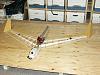
Photo 19 gives big hint on what the paint scheme is going to look like. Fuselage pieces that hide the fuel tank and electronics. Fuselage doesn't have to carry much flight load, other than its own weight. All the heavy stuff is located inside the wood skid.

photo 20 shows a wing skin to give a better idea of the paint scheme...

Next post will show wood shaping, servo mounts etc...
Mike