Dear all
So moving onto stage 2. I decided to do all the pipework for the J2 engines.
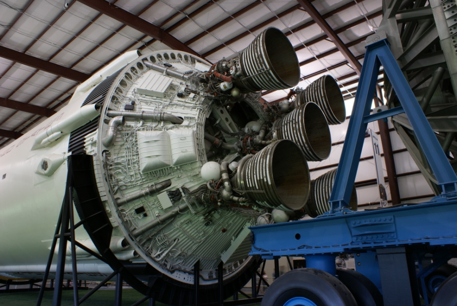
Since these pipes are in the updates parts there are no instructions as such so I found using the photos of
heroicrelics.org: Relics of the Heroic Age of Manned Space Flight the best things to work from. For example photos like this
So first some long pipework was formed which was then angle trimmed to meet with the thrust structure


Next was the "bend section" which was rolled but not glued. Then inserted into the main pipe to get the correct diameter fit (as shown). The other end of the bed section was checked to be "easily " smaller diameter than the LH2 pipe of the engine it would eventually go into.


Next the engine was located onto the thrust structure and the main pipe glued into position

When gluing this pipe i had a choice. To run vertical and NOT be in line with the fairings that would eventually go on the outside of stage 2 or to run at an angle and be in line with the fairings. As you can see in the picture from herorelics on the real Saturn V the LH2 intake to the J2 engines are in line with the fairings. The reason for the difference in the model is the J2 engines do not match with the cross member (it is a bit of a compromise attaching the J2's to the thrust structure). So in the end I went for vertical pipes.
The the bend section was glued into place. I really did not get a "good bend" so decided to cover things up with holding brackets


Then to finish off an engine I extended the LOX pipe into the thrust structure


For the centre engine I made the pipes that are on the cone part of the thrust structure which go through the holes in the structure. I found using the "widest" of the bracket pieces useful here to hide the bend area.

However I did not run any piping across the cross beam to the centre engine since I was not able to make a decent pipe bend into the engine inlet pipes. So instead I just extended the LH2 and LOX straight into the thrust structure.
Then I did the remaining engines. Here are some photos of the finished pipe work.


So that is all the thrust structure and engines of stage 2 finished. So all that remains for stage two are the umbilical tunnel and fairings on the main body of stage 2.
Regards
Kevin