Hello everybody,
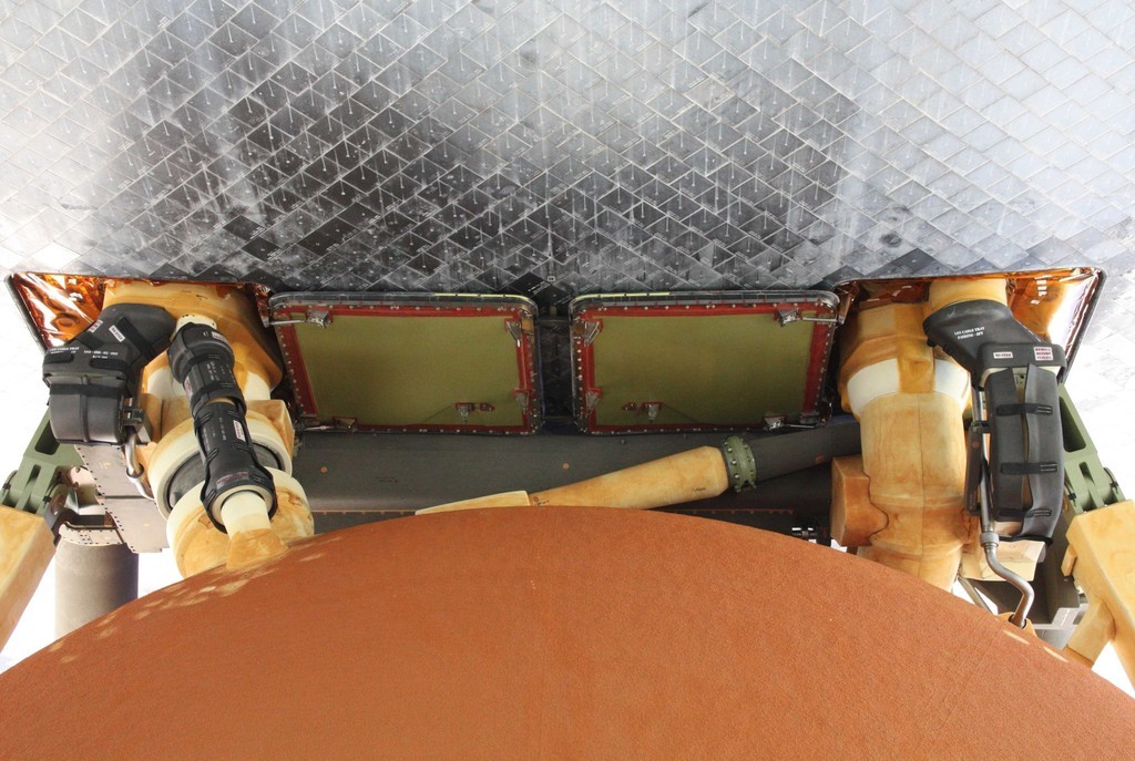
but as I mean by this time, these recesses in the upper rings seem to be filled up conclusively with the appropriate
TPS material, which is why it is unnecessary.
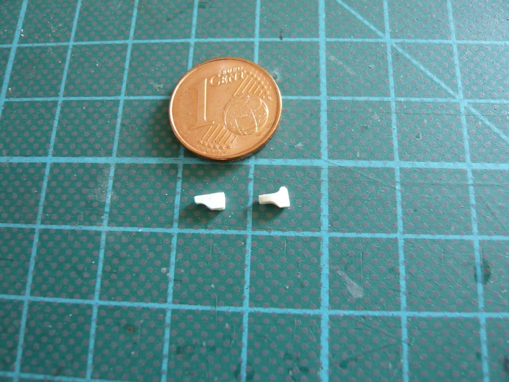
Furthermore the
Support Brackets for the
LH2 Feedline also look different and are also mounted differently than the brackets for the
LO2 Feedline on the right side.
 Source: NASA
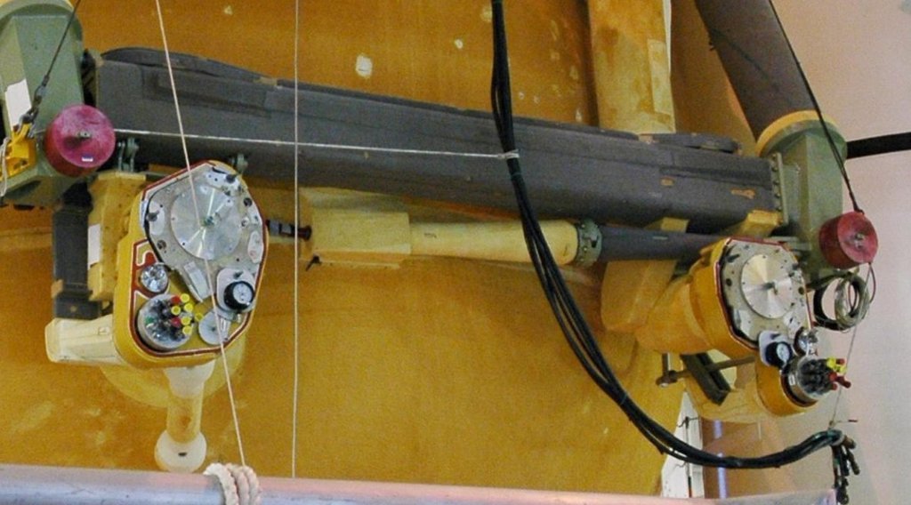
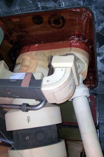
As can be seen from this image, the two
LH2 Brackets are not rigidly connected to the crossbeam like the
LO2 Brackets, but rather are slightly laterally movable by
Hinge elements, which is said to allow unrestricted relative distortion between the rear ET and the orbiter.
 Source: NASA
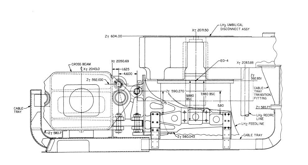
More precise information about the shape of the outer
LH2 Bracket is given by this drawing, from which I have also determined the dimensions, whereby I've used the width of the
Airfix Crossbeam (2,7 mm) as reference measure.

 Source: System Definition Handbook SLWT, Vol. II (Lockheed Martin)
However, one has to keep in mind that this is the
SLWT Handbook, i.e. this is how the
Super Lightweight Tank (SLWT) looked like, which was used starting at the end of 1998, with some modifications in order to reduce weight in favor of larger payloads, compared to the
Lightweight Tank (LWT) used for the first time at
STS-6 (ET-8).
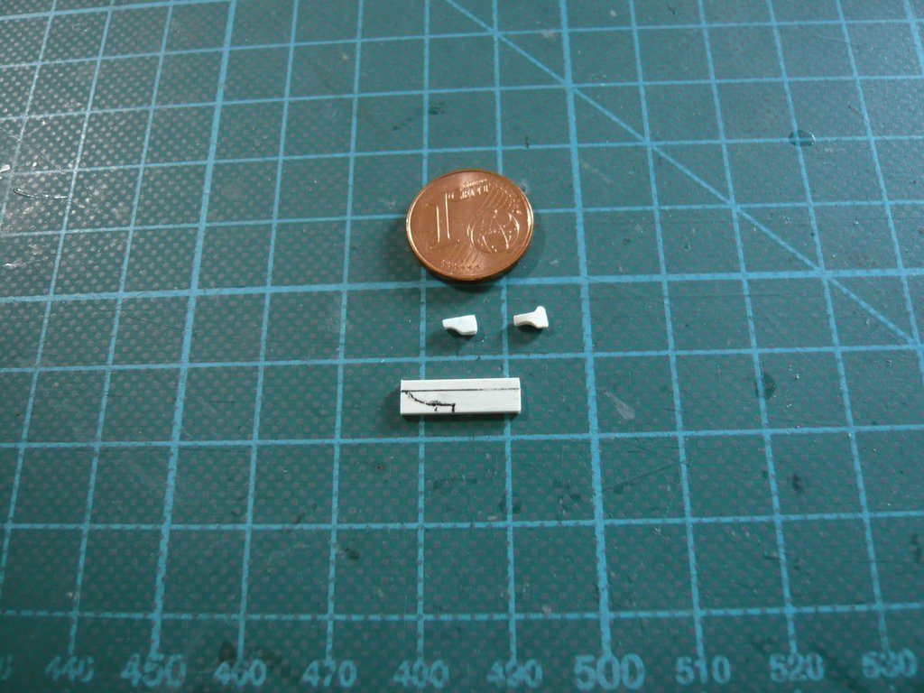
And as a further closer look at just this ET-8 shows, the inner bracket looks a bit different than my previous one,
 Source: forum.nasaspaceflight.com (Jester)
which is why I've modified it a bit (right).
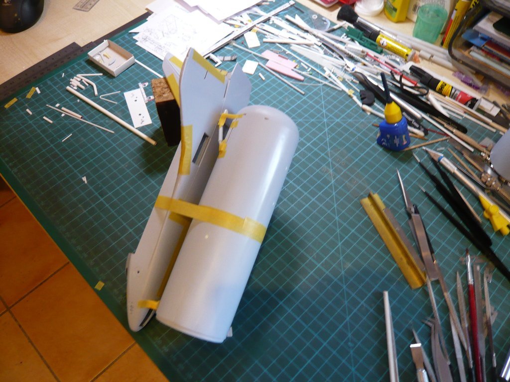
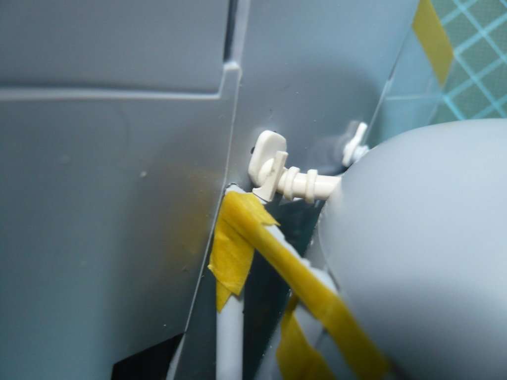
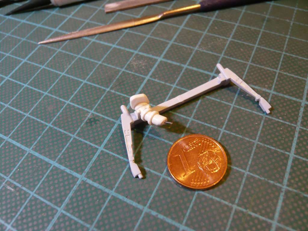
In order to finally fix the brackets and bond them with the Crossbeam, I put the Orbiter back on and fixed it with tape to see the exact distances and to adjust the brackets accordingly.
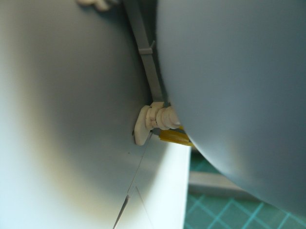
And in this position, the inner bracket was glued by using
MEK with the
Crossbeam and the
LH2 Feedline.

And now to the preparation of the outer bracket, which is drawn slightly longer, to which later the two holders for the
LH2 Cable Tray are glued, as can be seen from the drawing.
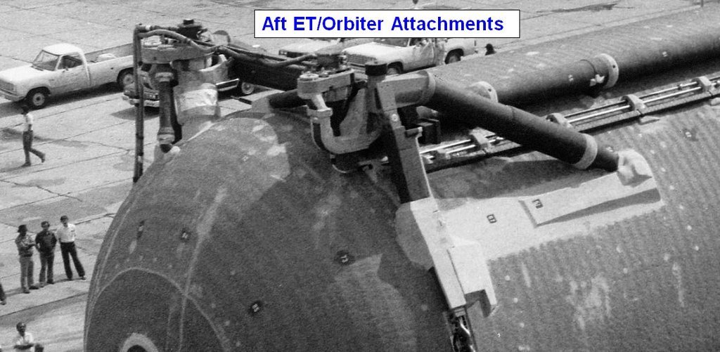
The front cable tray mount is nice to see in this photo, but whereby the two
Umbilical photos in the
capcomespace dossier are reversed unfortunately.

 Source: capcomespace.net
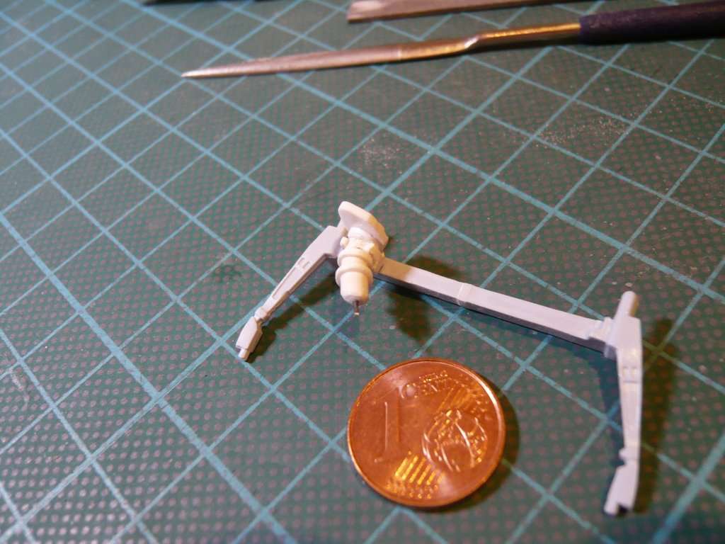
This was followed by the fitting of the outer bracket,
and their cutback to the right length,
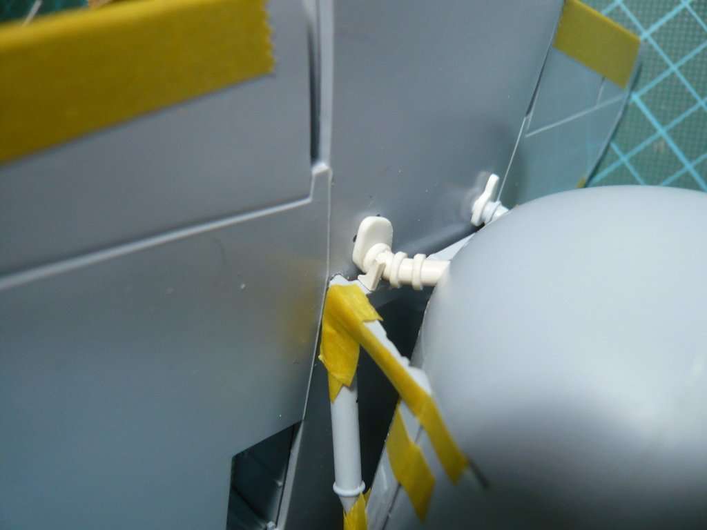
and finally their gluing with the crossbeam and the feedline with MEK.
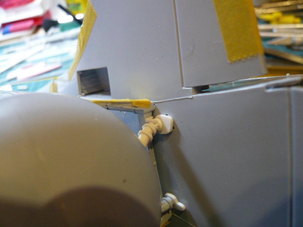
Then I was able to remove the orbiter again and scrutinize from all sides the [color= blue]LH2 Feedline[/color], glued on the crossbeam.

And now I could either glue the
LO2 Feedline Brackets or lay the
LH2 Cable Tray on the front of the Crossbeam.

