Hello everybody,
and after the end piece of the
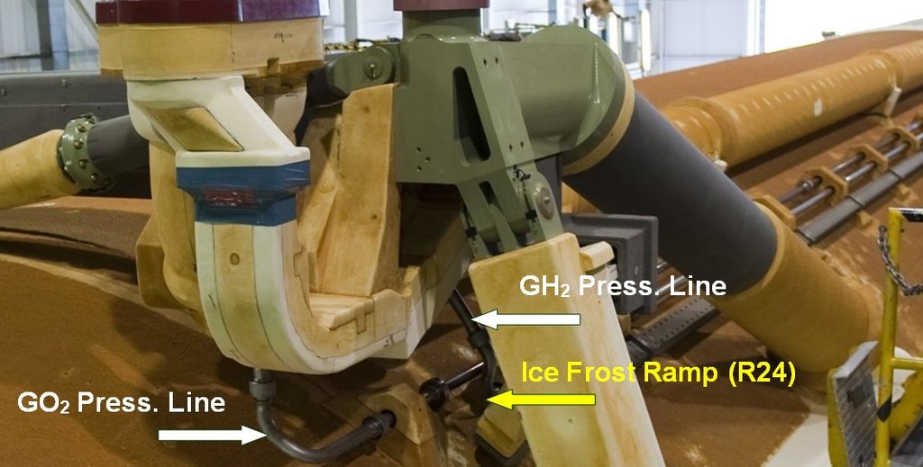
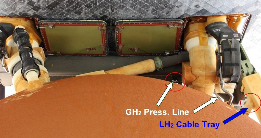
GO2 Press. Line now to the end piece of the
GH2 Press. Line, which directly lies next to it and after two bendings runs slantwise upwards in the direction of
Crossbeam, as one can see on this image.

 Source: NASA
With this line I want to proceed the same as with the
GO2 Press. Line and initially only bend its end piece from the last
Ice Frost Ramp (R24) to the
TPS cladding under the
Crossbeam, because the continuation of the line on the
LH2 Tank until the
Fairing on the
Intertank should also be installed separately.
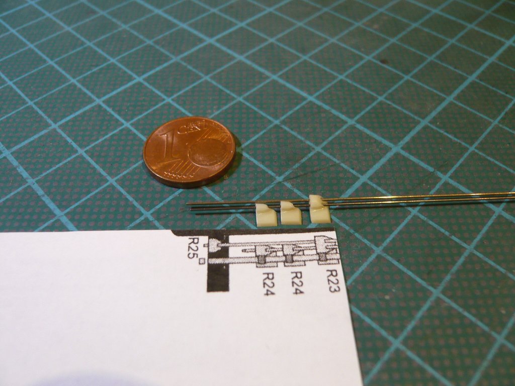
In the following image I have used a
Steel rod (Ø 0,4mm) for the
GH2 Press. Line and threaded it into the back three
Resin ramps from the
Newware Kit (NW 131).
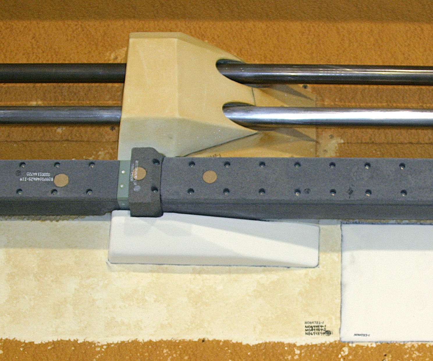
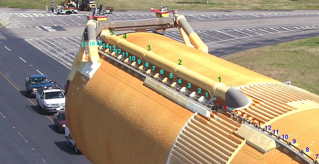
On this photo one can see an
Original ramp with the two
Press. Lines, as well as the
LH2 Cable Tray runnig below.
 Source: NASA
And already as forward look and for the sake of completeness, in the following image are to see the
17 Ice Frost Ramps on the
LH2 Tank , whereby the
Ramps 1-14 (R23) are "Double"-Ramps (see previous photo).
 Source: NASA
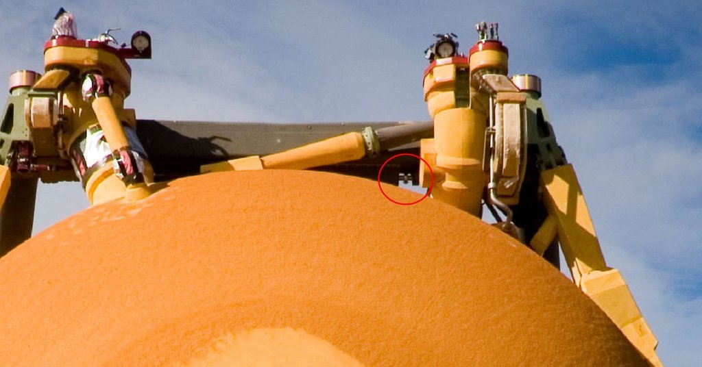
The connection point of this line piece at the
TPS cladding under the
Crossbeam can be seen in the following photos.
 Source: NASA
 Source: forum.nasaspaceflight.com (Jester)
In this photo one can see in the zoom that in front of the
Fitting in front of the
TPS cladding also still a small
Support is sitting.

 Source: forum.nasaspaceflight.com (DDG40)
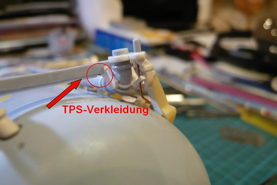
And that is this point here on the model, which has unfortunately proved to be too low with detailed review

and measurement of the gap to the
LO2 Feedline Bracket,

which is why I had to shorten the
TPS cladding very carefully a little bit with a razor blade to create the required space for the little
Support.

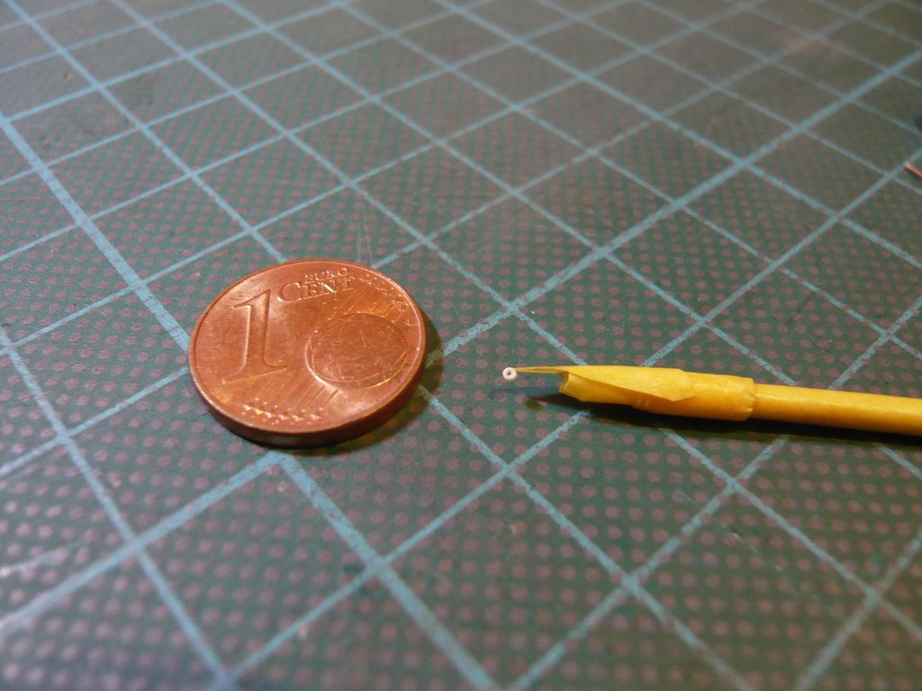
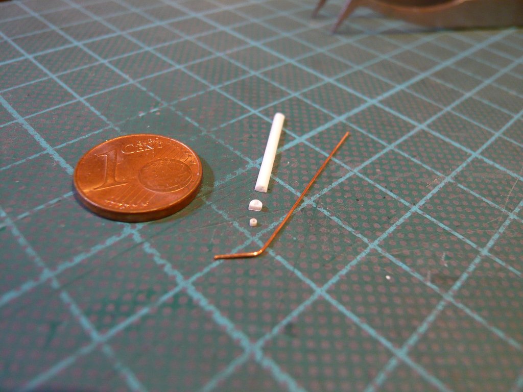
And these are the required separates. The small
Support I've cut off from the rest of the
TPS cladding, in front of it lies the tiny
Fitting made of
Insulating hose, and in front of them the
Cu dummy for the end piece of the
Press. Line (Ø 0,4 mm).
And the test fitting of the
Press. Line looks already rather well.

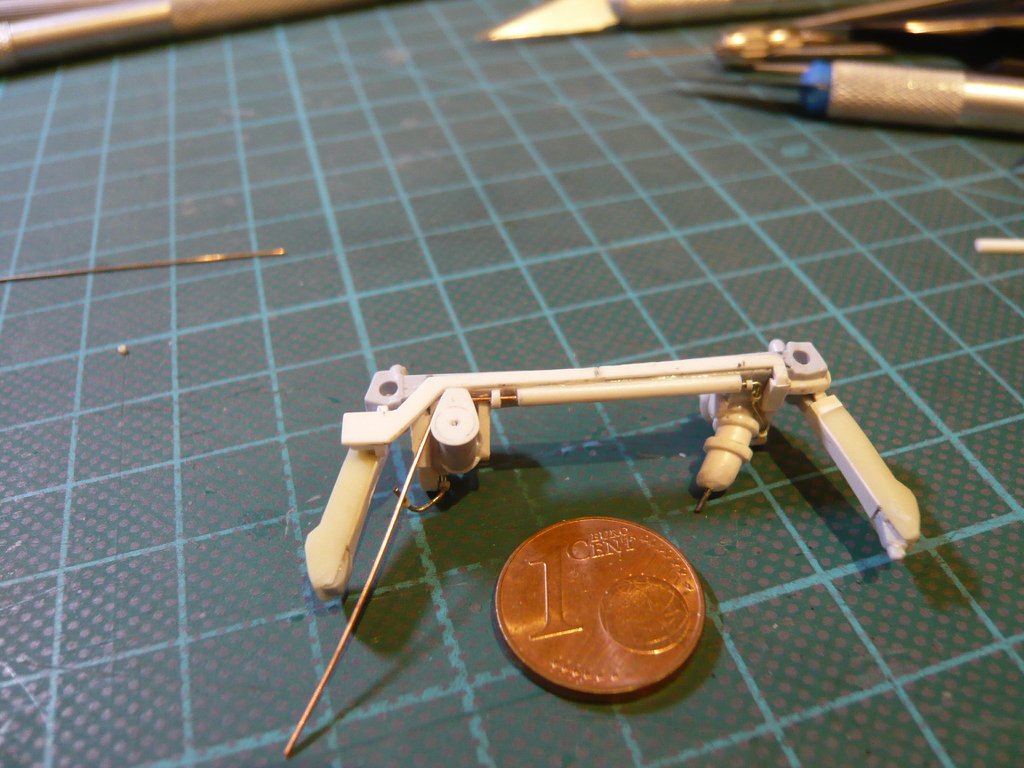
But with that I was again faced with the same problem of threading the tiny
Fitting in the space of this gap ...

But meanwhile I have some practice with it, and that's why I have prepared this time again a small
Toothpick-Tape holder, as at that time in a similar action at the
SSWS on the
MLP,
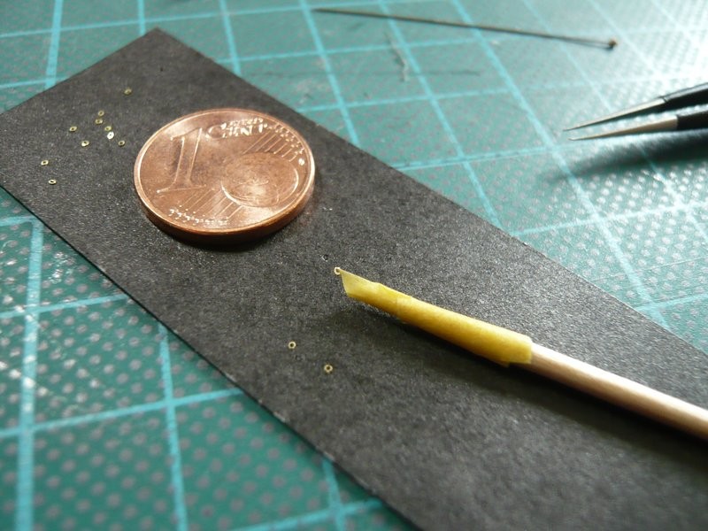
at its top of which this time the
Fitting hung.