Hello everyone after the 4th Advent,

it goes on, and with that I come back to the
Crawler drawings (John Cato) to determine the missing dimensions of the profiles that are required for the
Scratch-build of the
Crawler chassis.

However, these drawings are not understandable straight away, what i.a. is due to the ambiguity of the English technical terms used for the different profiles as
Trusses and
Pipe Girders, which are by no means self-explanatory.

So one can find terms such as
Longitudinal Truss, Lateral Truss, Diagonal Truss and
Diagonal Box, and then also still
Beams in the legend.

At that I believe that the term
Truss not only means
Girder per se, but rather the
Truss structure which is located between the girders, as still will be seen from the drawings.
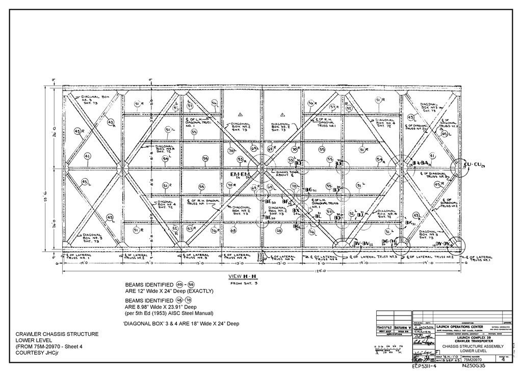
Furthermore, it has gradually become clear to me in the meantime that not only the outer Longitudinal girders marked red in my previous reply (
#2307) on the lower chassis structure (
Lower Level, Sheet 4) are
Boxes, but that there are also further Boxes.
In order to be able to recognize this, one has to look at the original drawing more closely,
 Source: savethelut.org (John Cato)
wherefor one has to choose a higher resolution,

what I did in the following excerpt,
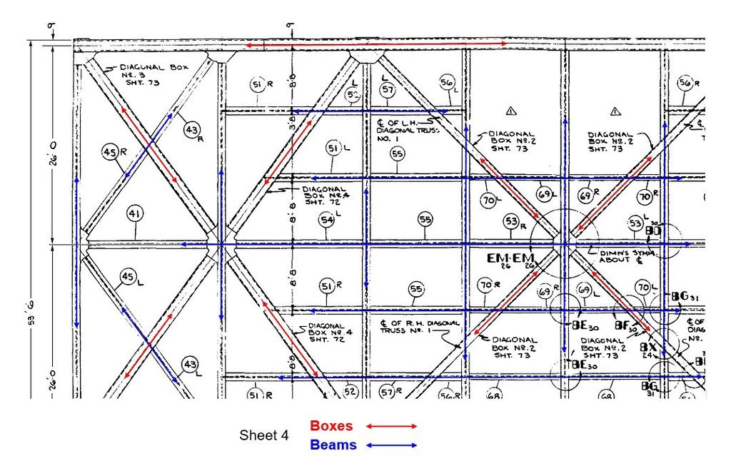
and what should be explained in this further enlarged image section based on the different types of lines.
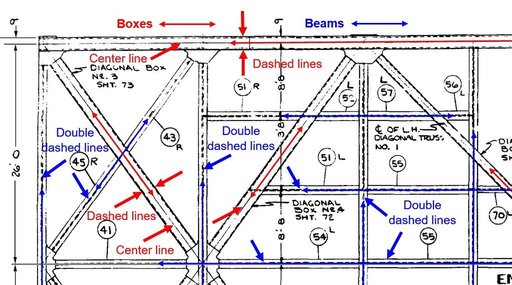
In it one can see
center lines in the middle of the
Box profile (red) and
dashed lines on both edges what indicates welded box girders with a rectangular cross-section, in other words
square tubes, the cross-section of which was already shown in the last post in
Sheet 34 to determine their dimensions.

The
Beam profiles (blue), also known in German writings as
Double T-beams (I-beams), have [color= blue]double dashed lines[/color] belonging to the middle
Web) of the profiles, which is concealed by the upper [color = blue]Flange[/ color]), for which one can also find the terms
Wide Flange Beam or
H-Beam in Anglo-American writings.
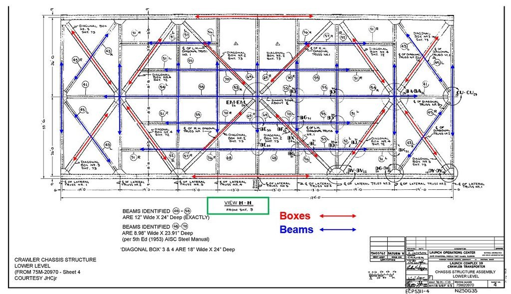
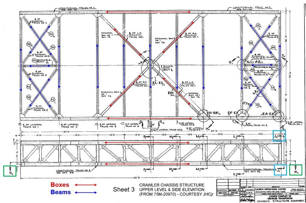
This image shows once more the overall structure of the lower chassis level (
Sheet 4) with all the profiles that are needed for scratch-modeling.

The upper frame structure (
Upper Level) can be seen from
Sheet 3 in the following picture and has a similar structure consisting of Box and Beam profiles, whereby I don't need to scratch this framework, because the space underneath is needed to accommodate the electrics/electronics of the
current supply, what I have already explained.
More important for
scratch-building is the associated
Side elevation of the frame structure
Longitudinal truss with the
Pipe Girders at the lower edge of the image, which contains some sectional views that are important for the further construction, which in turn can be found in other drawings.
 Source: savethelut.org (John Cato)
The
View H-H (green) refers to the already discussed lower frame structure
Lower Level (Sheet 4). With
View J-J (light blue) it is referred to the first of the nine lateral trusses (
Lateral Truss No. 1) in
Sheet 5, which I will go into later.
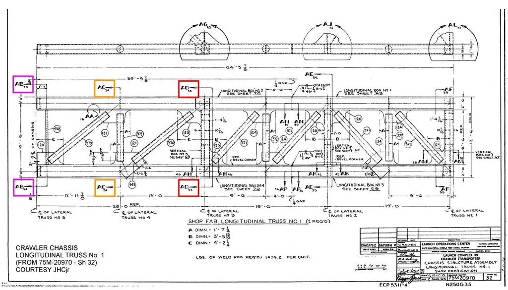
Also important for scratch-building are the dimensions of the
Pipe Girders, which can be seen from sectional views to which is referred in the following drawing of the
Longitudinal Truss No. 1) in
Sheet 32.
 Source: savethelut.org (John Cato)
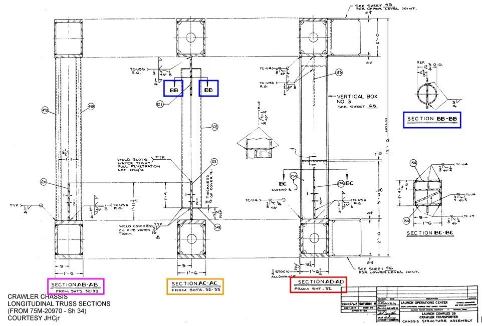
The marked
Section AC-AC (yellow) can be seen in
Sheet 34 and shows a cross section of the welded box girders (
Boxes) of the
Longitudinal Truss No. 1, which even differ slightly.
 Source: savethelut.org (John Cato)
In this sectional view, the
Section BB-BB (dark blue) is marked through the
Pipe Girder there, the cross-section of which can be seen on the right edge of the image, from which the diameter of this support tube with
12¾" can be seen, which corresponds to
Ø 2,0 mm (1: 160), which for all
Pipe Girders of the two
Longitudinal Trusses No. 1 & 2 is the same.
The same diameter is also obtained if the height of the
Box profile (2'-0) is used as a reference dimension.
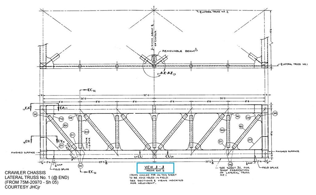
With this I'm coming back to the already mentioned
Lateral Truss No. 1) in
Sheet 5 (View J-J), which can be seen in the following image and shows the structure of the
front and rear of the Crawler chassis.
 Source: savethelut.org (John Cato)
If one uses the height of the
Box profile (2'-0) as a reference dimension in this drawing, the diameters of the vertical and slanted support tubes (
8,6'') result with
Ø 1,4 mm, which are also the same for all
Pipe Girders of the trusses in the interior of the crawler, as I have learned from
Mischa Klement.

With this I have now determined the essential dimensions of the profiles for my scratch-building of the
Crawler chassis, wherewith I can let it go at that for the time being.
