Instead, I came up with the idea and tried it in
MS Word.

To do this, I used the
Insert shapes mode to arrange small rectangles of the appropriate size with the finest line thickness as contours of the parts and gaps on the floor plate, which was a bit tedious, but after some practice it worked very well and gave an exact picture of both plates.

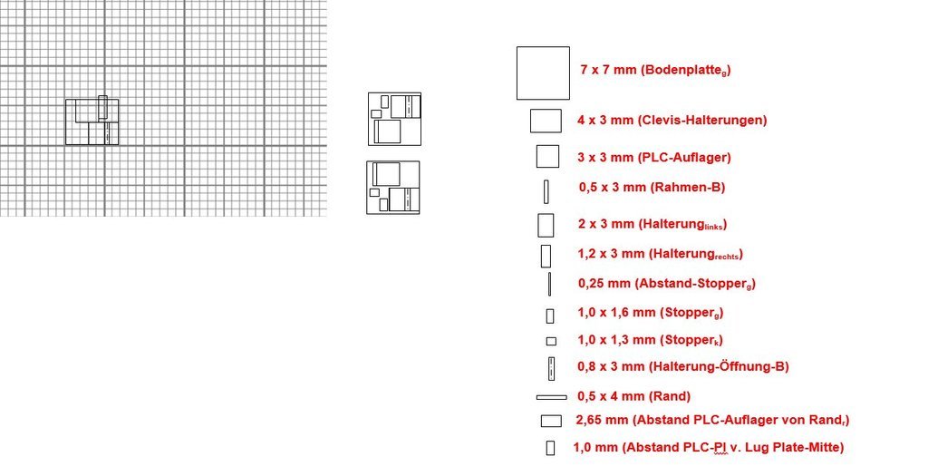
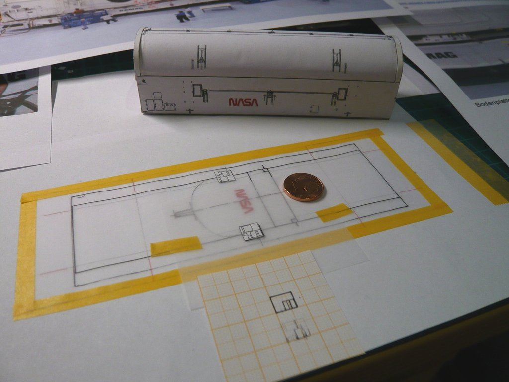
I then printed them out, although one can be shocked when one can see how small everything will become.

Since the arrangement of the plate parts on the other side has to be laterally reversed, I also printed it out on transparent paper (right) and therefore only have to turn it over.

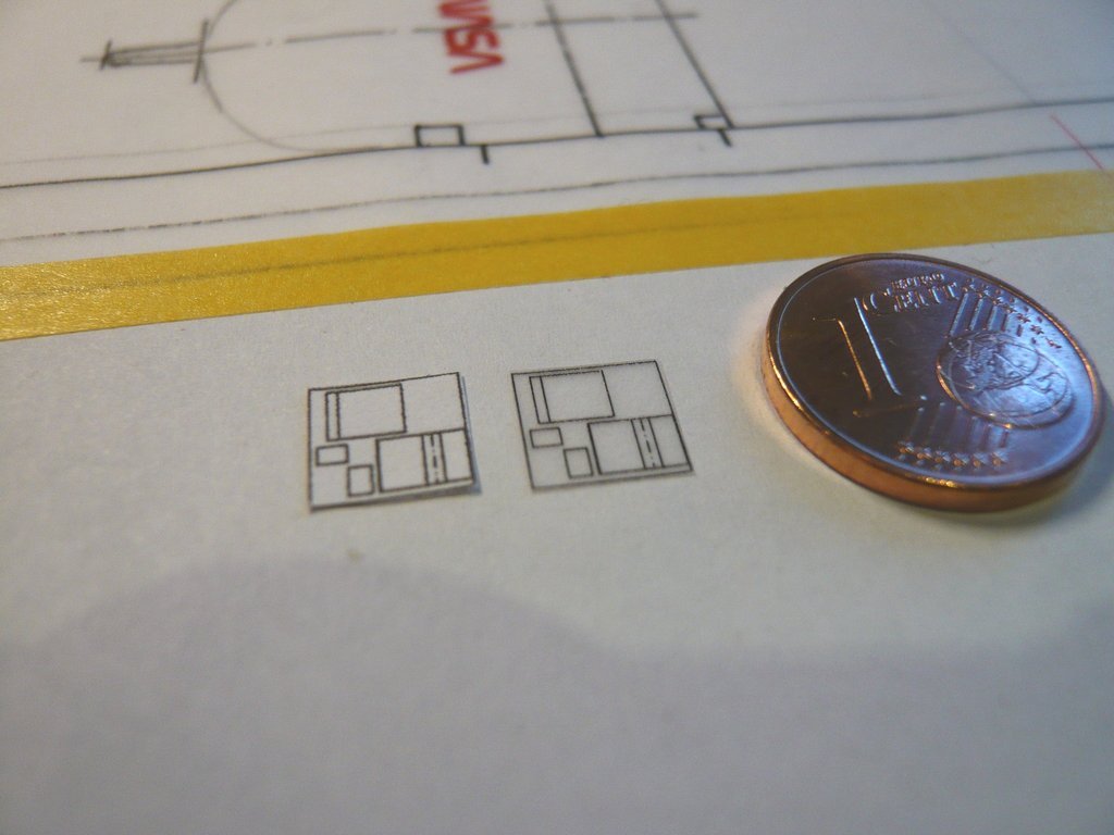
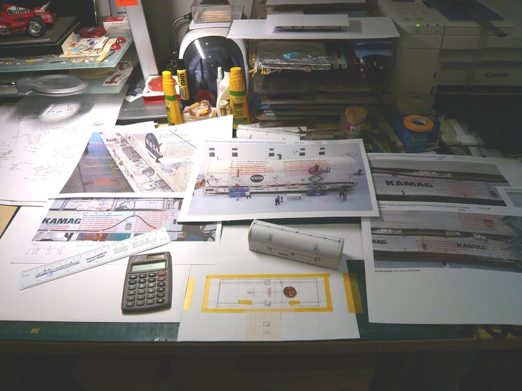
And this is what the two larger Transportation support plates look like.
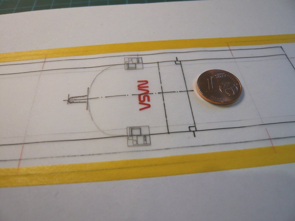
So at least the arrangement of the individual parts on the floor plate is clear, but now I also need the
heights of the parts in order to be able to scratch them.

And I will now determine those again using the
height of the side wall (7,5 mm) as a reference,
whereby I have to be careful, because they were sometimes incorrectly determined from
reference lengths in various photos.

And with a table full of dimensioned photos, one can start to skid and lose track.

Therefore a cool head as well as
highest concentration are required!

