Hello Guys,
after I did successfully scratch the first
Hold-down clevis quite well, I've glued the remaining three clevises together too.

Because the simultaneous gluing of the plates with
MEK proved to be too unstable due to the minimal adhesive edges, I proceeded a little differently this time and used my steady hand and my eagle eyes trusted.

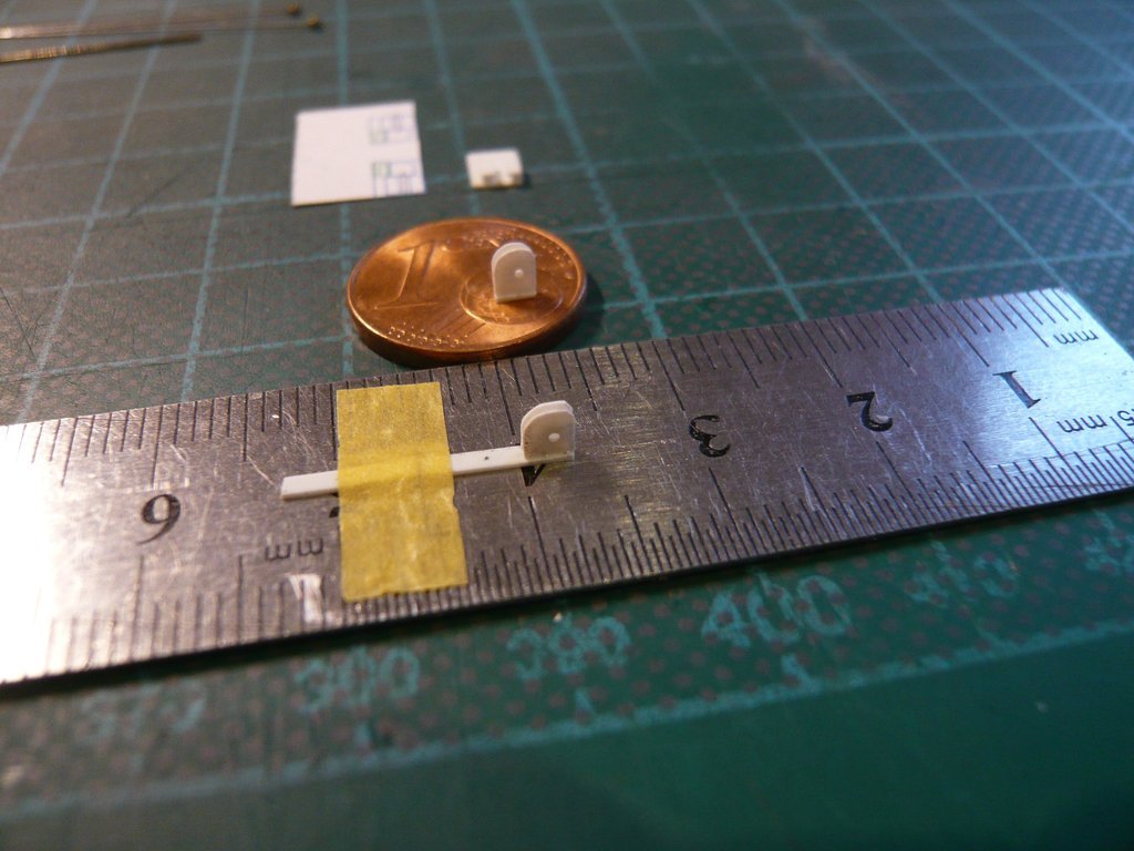
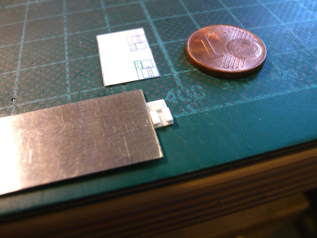
This time I fixed the
base plate strip (1,3 m) to a steel ruler so that nothing could slip. Then I wet a
Clevis plate lightly on the lower edge with
Revell glue and carefully close to the edge of the strip (approx. 0,2 mm) placed at its end. After that, there was still enough time for the finest position corrections.
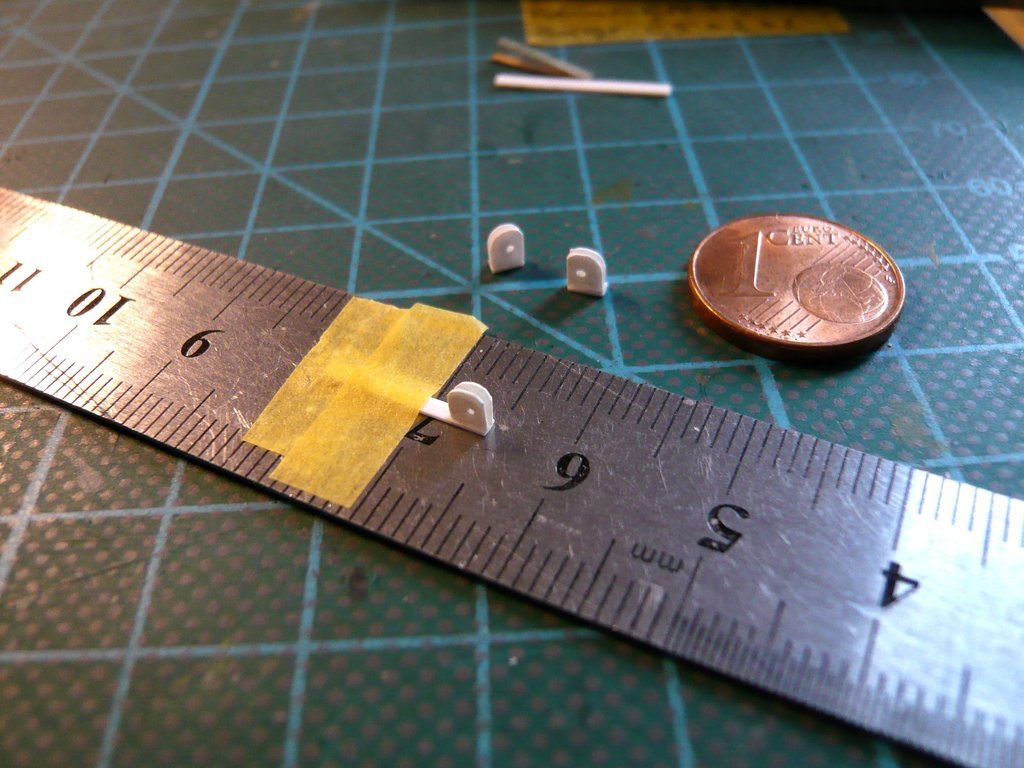
I then glued the other plate in the same way, inserted a spacer strip the thickness of the
Tie-down Lug Plate (0,4 mm) between the plates and gently pressed both together with the tweezers. Then the position of the plates was adjusted to each other and the central position of the pair of plates was checked and adjusted if necessary, which worked quite well.

After that, to be on the safe side, I brushed the glued areas of both plates with
MEK and cut off the base plate strip flush,
and the second Clevis was done too.

The two remaining Clevises then followed in the same way.
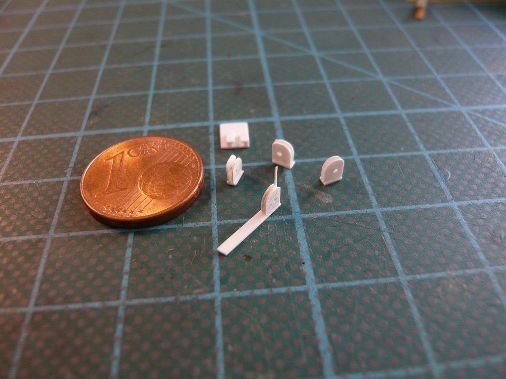
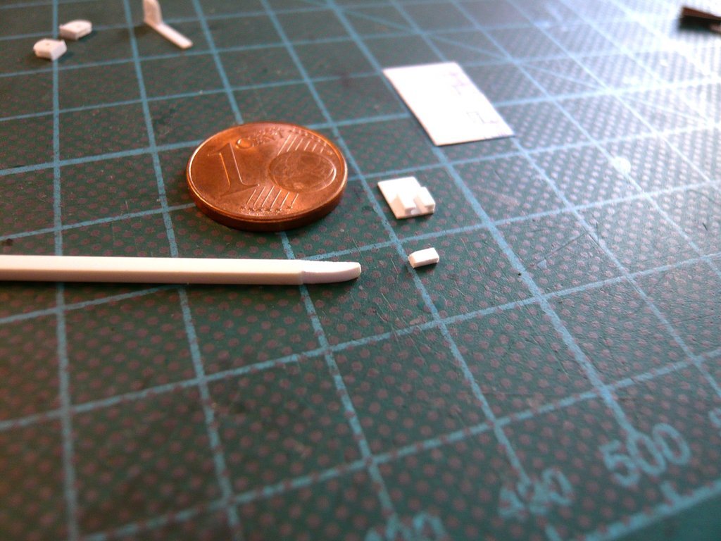
And as one can see, the
Tie-down Lug Plate still fits in between, which was my biggest concern at first.

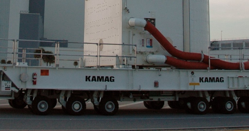
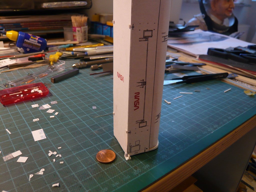
Next I tackled the two
stoppers that one can see in this image on either side of the bottom of the canister. In my opinion these are more likely to be
Sliding shoes for the
Payload Canister, through which is guaranteed a certain guidance of the canister when the canister is set down on the
Transporter as well as during unloading and hoisting into the
RSS-Payload Bay.
 Source: wikimedia.org (STS-132)
The fact that this
PLC-Hoisting is an extremely complicated and not without danger process, I was just reading in
James MacLaren's Page 51 on the
Canister Hoisting System in his treatise about the structure of the
Launch Complex 39-B, what I can warmly recommend to all interested parties,

which made a lot of things clearer to me, such as the need for additional securing of the canister on the
"kneeling" transporter with several
Tethers (Tag lines) during the Canister is hanging on the crane hook.
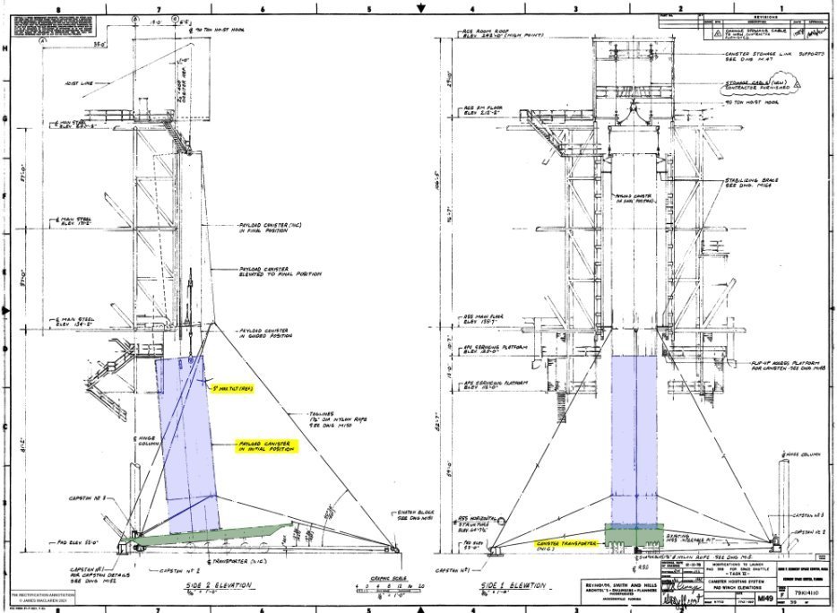 Source: James MacLaren - The Construction of Space Shuttle Launch Complex 39-B (Page 51)
The sliding shoes sit on
base plates, which are screwed onto the smaller
Transportation Support Plates of the transporter during the
Vertical Transportation mode.
For the base plate I used an
Evergreen strip (0,75 mm x 1,5 mm), which I filed down to a
width of 1,2 mm and cropped to
2,4 mm length.
For the sliding shoe, I filed an
Evergreen strip (1,5 mm x 1,5 mm) to
1,2 mm x 1,3 mm, which was cropped to
3,5 mm length.
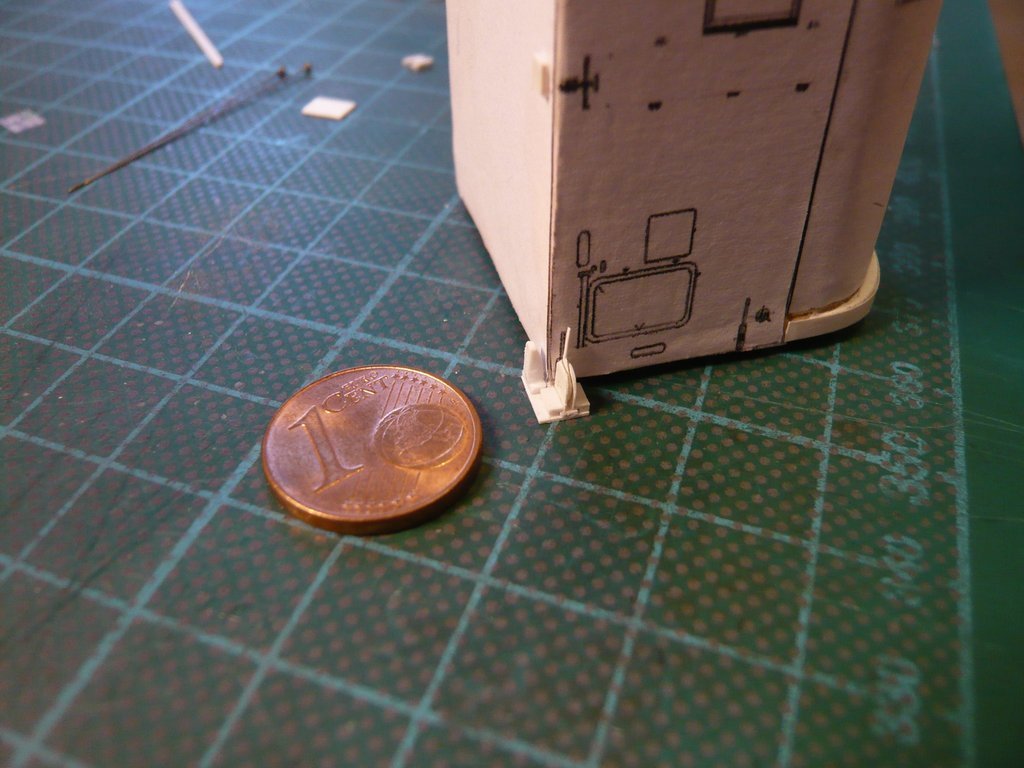
Then I wanted to do a first
vertical test fitting of the canister on this transport plate and I have glued on the
PLC base plate (0,5 mm x 2 mm x 2 mm) as a support for the canister,
have temporarily put the base plate of the sliding shoe on and set up the canister, what fits together quite well.
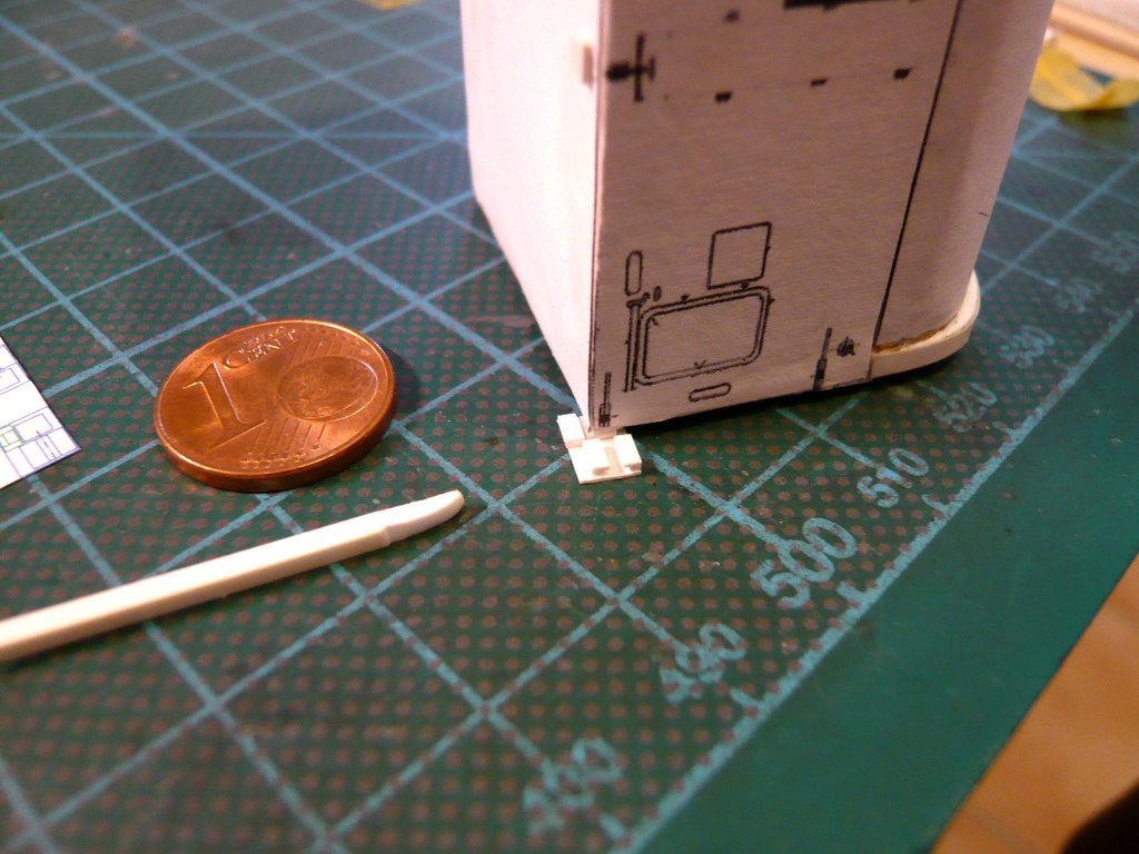
And this is what the finished sliding shoe looks like,
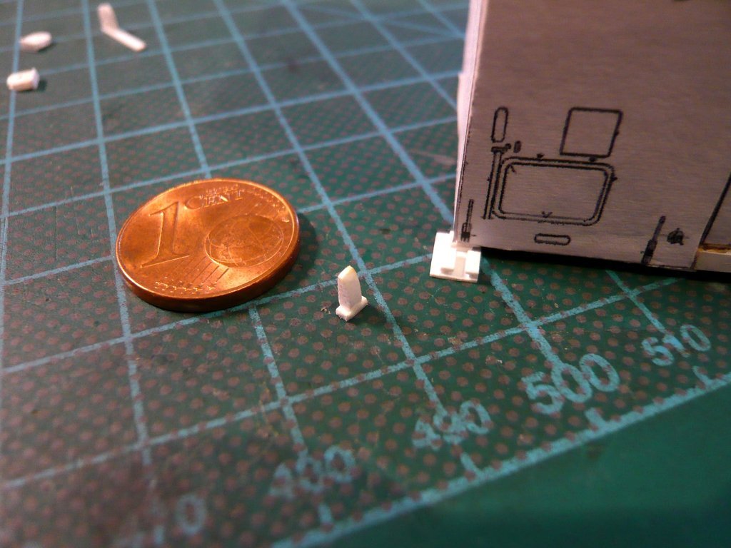
which is here standing on the plate, in front of it the
Clevis is standing already,
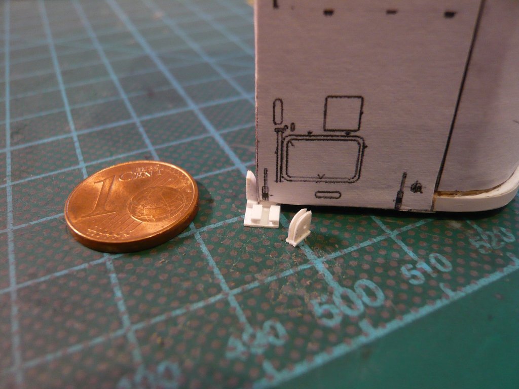
which is inserted here with the inserted
Lug Plate in the brackets,
but what is hardly recognizable from this distance.
The same Transportation support plate now will follow for the other corner, and then the two larger Transportation support plates will follow.

