Hello everybody,
and now to the assembly order, which I thought carefully about.

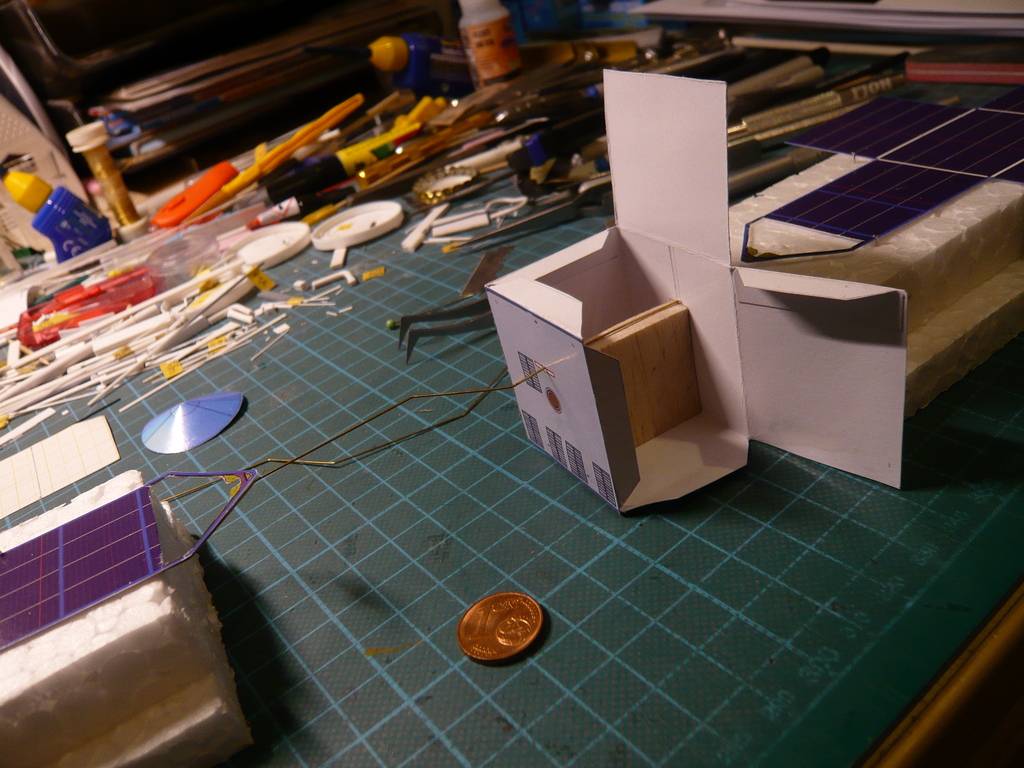
Since my two
Z-shaped brass struts are supposed to go through the
probe cube, it quickly became clear that I wasn't allowed to glue the cube together on all sides yet otherwise it would not be possible to thread the struts through.

That's why in the following picture I tried to mark the individual steps in order with arrows, which may not be understandable straight away,

which is why I would like to briefly explain the steps.
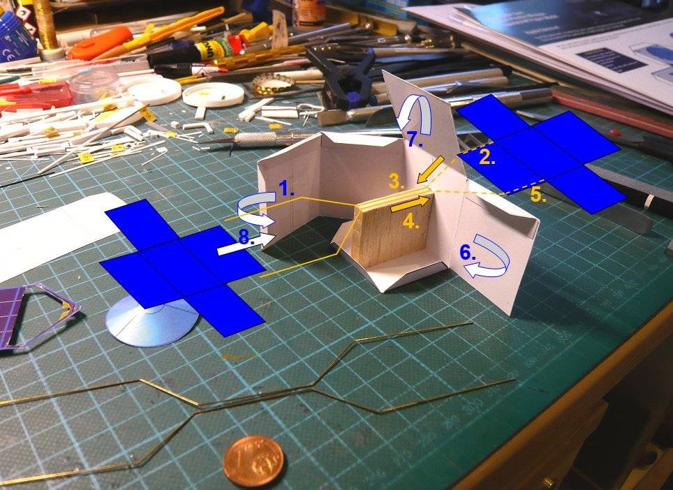
In order to still have enough freedom of movement when threading the struts, I can in the
1st Step first just only glue the two rear side walls to the floor and the
Balsa support.

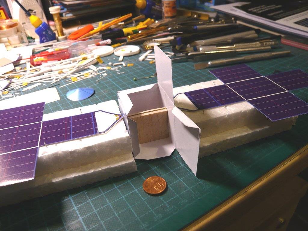
In the
2nd step I only glued the end of the
brass strut onto the back of the
upper panel with
UHU CA, because I might want to leave out the white
paper triangle.

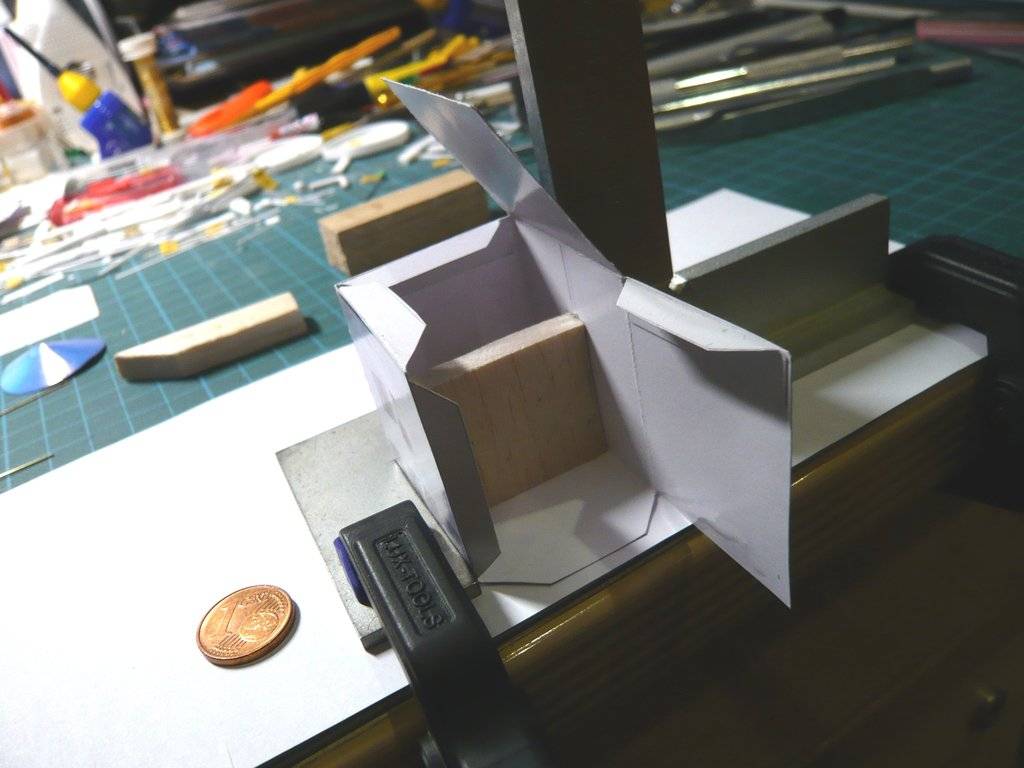
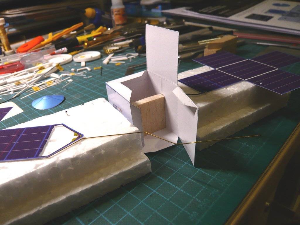
In order to be able to handle these bizarre structures when threading through the struts, I cut two
Styrofoam blocks to the required height to support the panels.
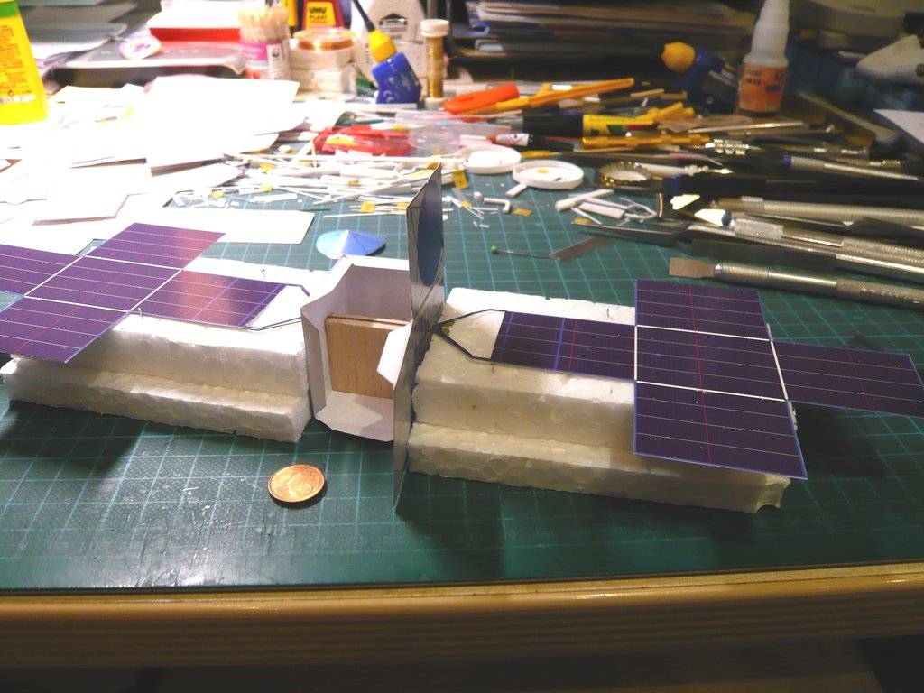
In the
3rd Step then followed the careful threading of the glued strut first through the front side wall and then by turning the rear support so that the strut could also be threaded into the rear side wall and then could carefully pulled through,
which actually worked.

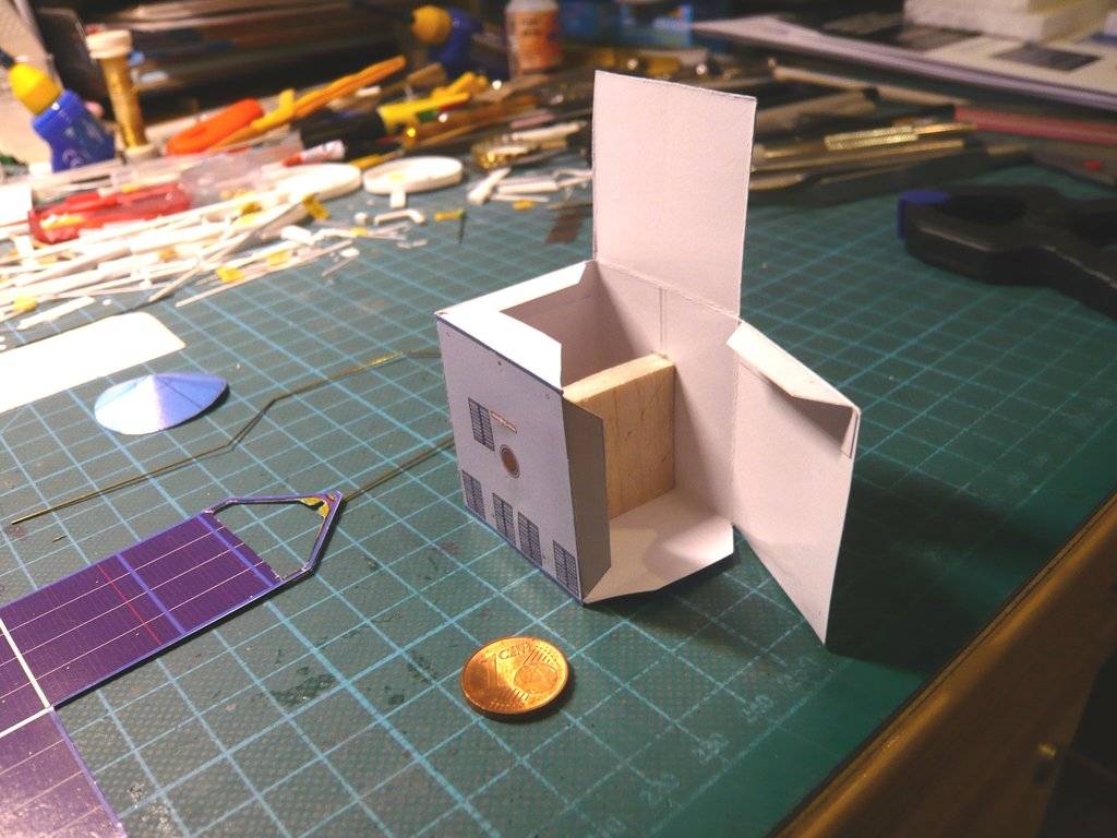
The other panel is only temporarily placed in these images.
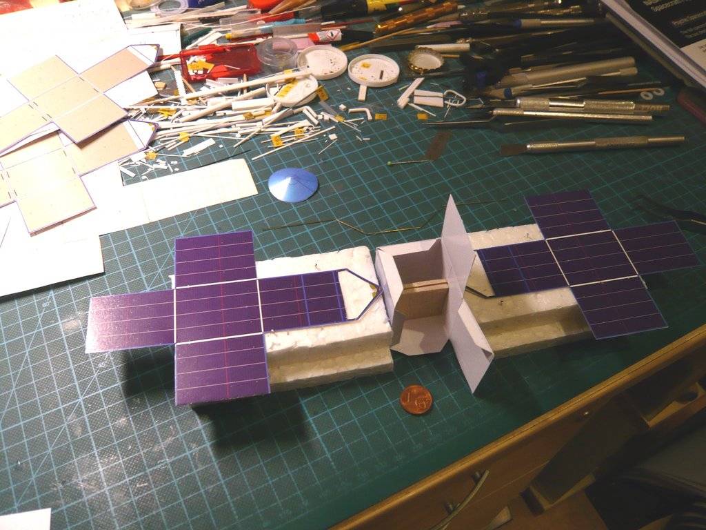
With this panel and the
Steps 4 to 8 it will continue tomorrow.

I hope you don't get confused.
