Hello friends,
due to a discussion in the
KitMaker Forum regarding my
'markings', where it was said that NASA used
white duck tape, I was even more interested in these markings on the solar probe's cladding.

Even if the arrangement of these strips of different lengths may seem completely arbitrary and irregular at first glance, these markings must have had a purpose, especially since in the zoom it looks as if they were
labels with legends, for whatever ...

 Source: NASA
 Source: NASA
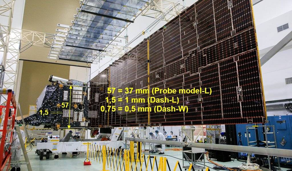
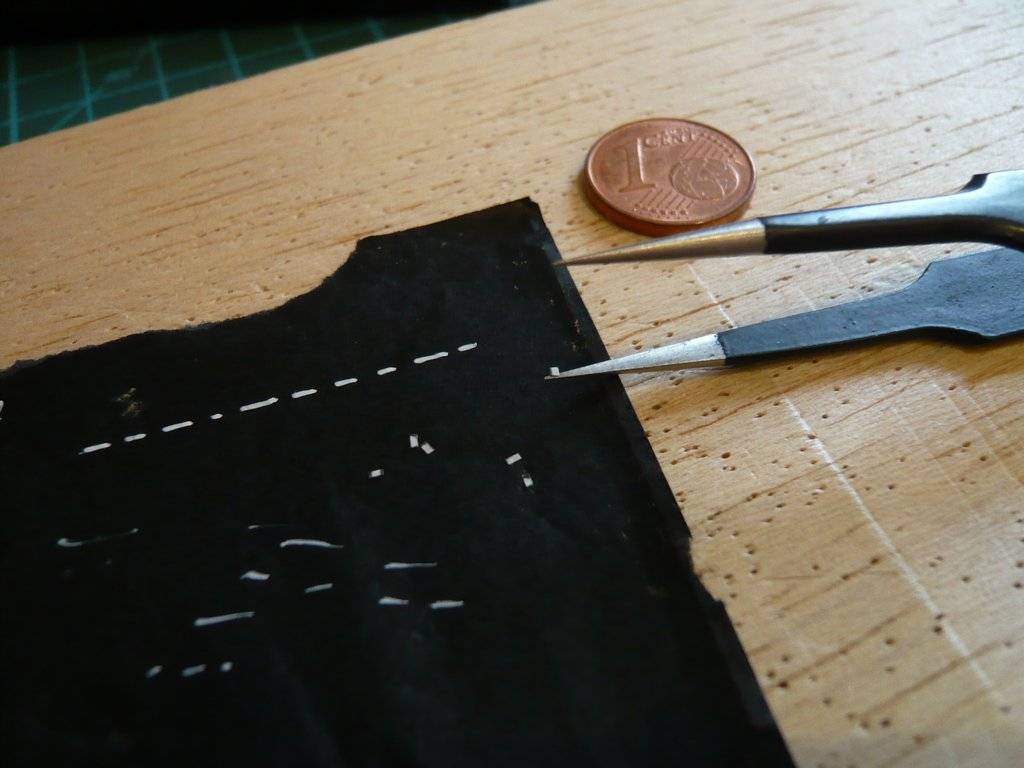
In this image, just for fun, I determined the dimensions of these markings for my model probe, according to which the tiny
lines (approx. 0,5 mm x 1 mm) should be.

 Source: NASA
Here I have drawn a corresponding
approx. 0,5 mm wide strip on
label paper, and marked then
1 mm long sections for the
mini labels,

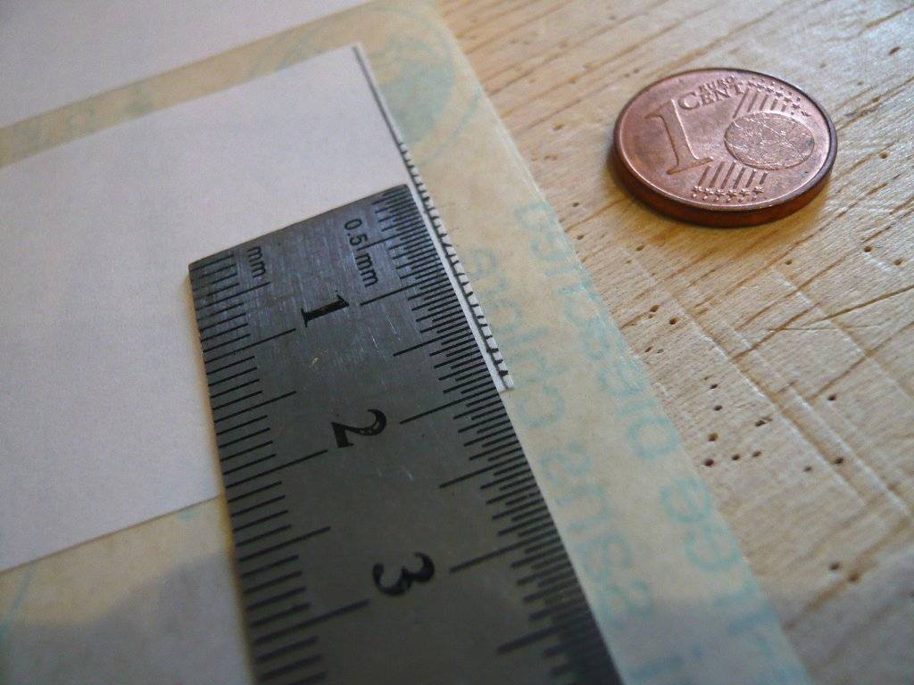
which then were cut off.
In a crazy action comparable to
mouse milking, as it is called in Germany,

Ive then patiently tried to use tweezers and a cutter to form a row that would now be roughly true to scale, while these 'dashed lines' are not so evenly arranged in reality.
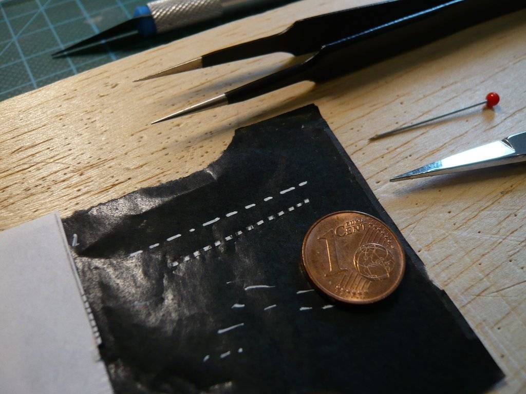
That's why one can see that my lines are too long, but with the
permanent marker (Montana Acrylic) you can't draw such tiny dashes, at best you can only hint at them.
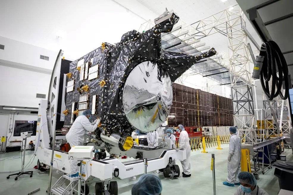
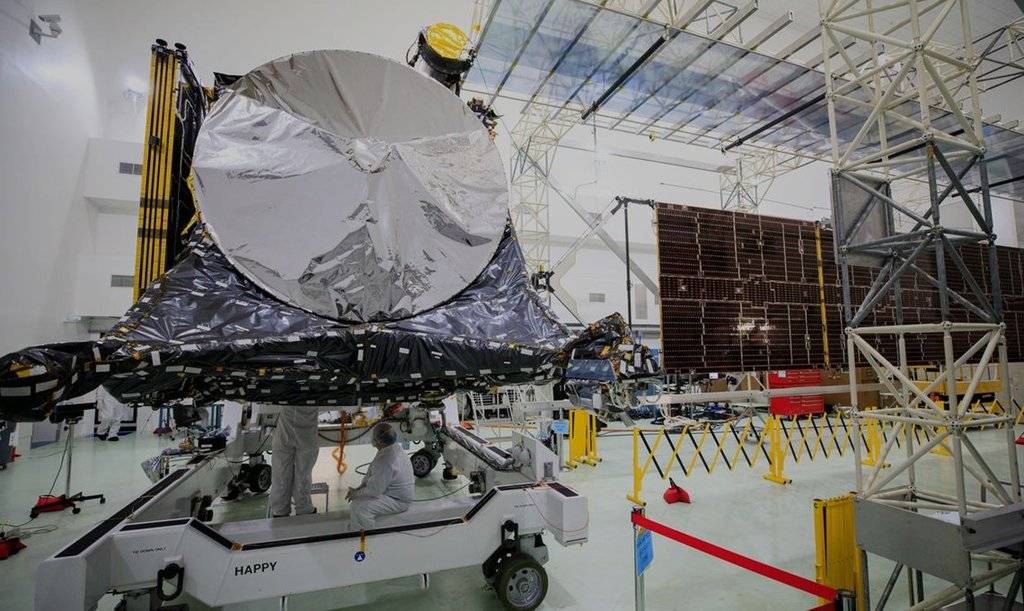
Then, during my research, I came across some
NASA original photos that I had not previously seen. Upon closer inspection, I became aware of further details that plays havoc with my previous view of these
rod systems and their
foil cladding,

which is why I have to rethink and modify my previous solution approach.

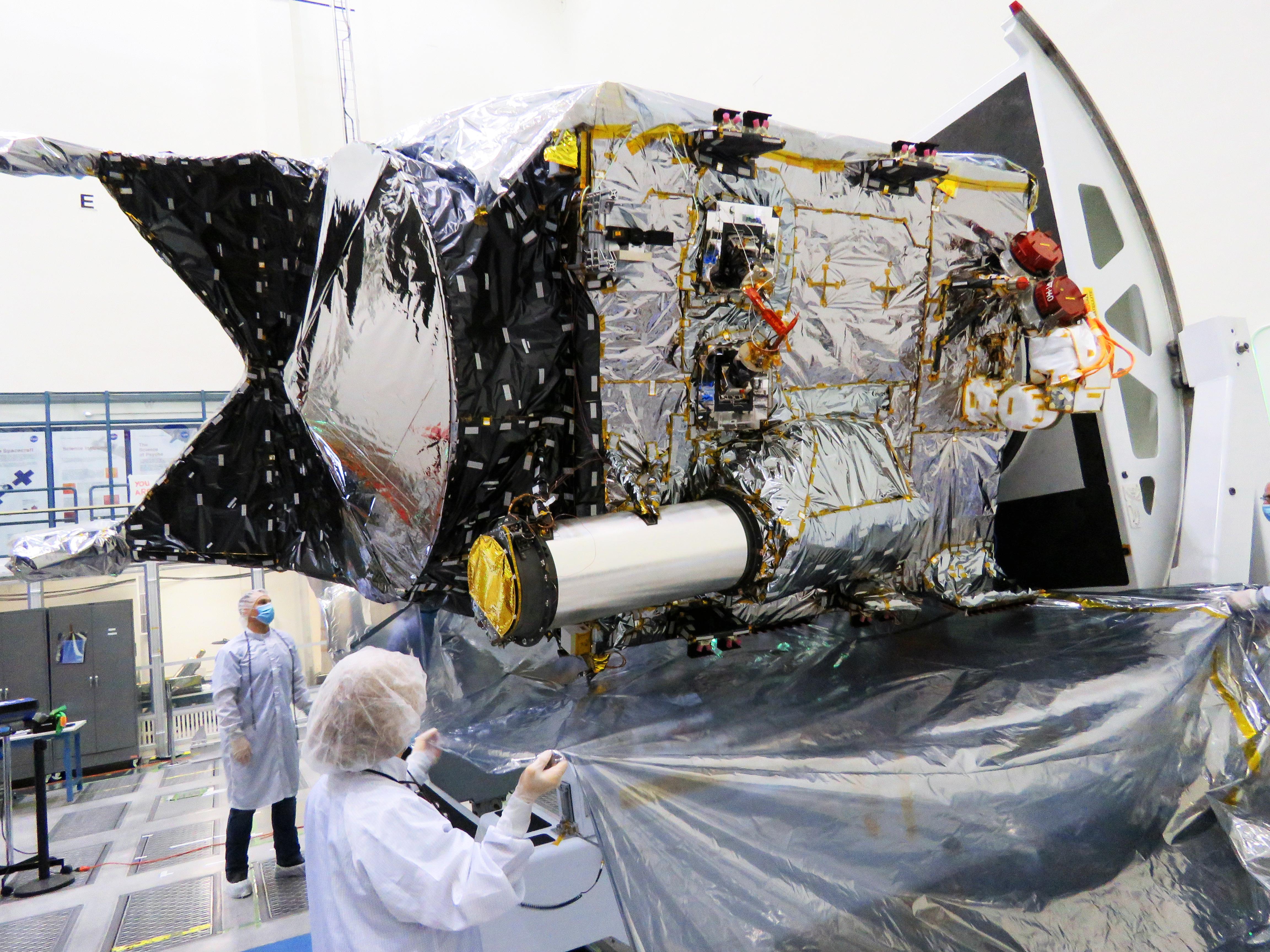
As one can see in this image (zoom!), the area between the rod systems behind the
X-Band High Gain Antenna is not open, but is also covered by dark foil with such strips, which means that the bottom part of the antenna is literally enveloped from behind,
 Source: NASA
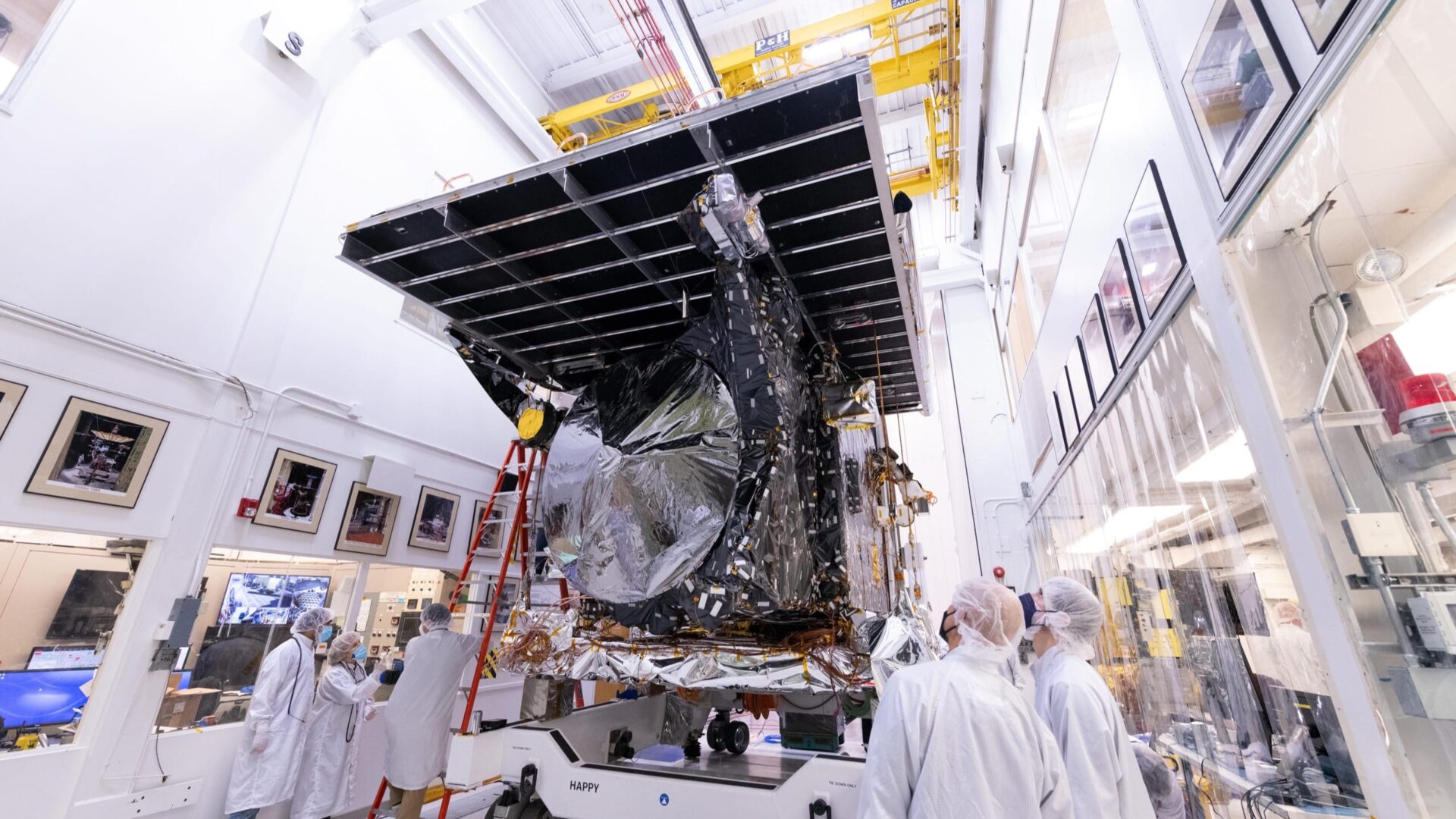
which can also be seen from this image (zoom!).
 Source: NASA
The bottom part of the antenna is also covered in dark foil all around, which I had already noticed and still needs to be taken into account.
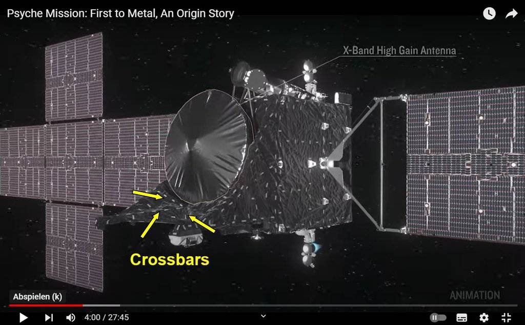
That's why there are
crossbars on the rear rod system that run diagonally downwards for attaching the film, which one can just about see in this image,

which appear under the cladding in this image too.
I now have to try to put these new insights into practice.

There's nothing like good
NASA original photos, you just have to know how and where to find them.

