


|
|
|
#11
 10-01-2011, 11:42 AM
|
|||
|
|||
|
Hi all,
Thanks for the interest and very encouraging comments. Following the fuselage assembly, I installed the cockpit with it's two frames to rigidize the fuselage at the area where the inner wings will be bonded. The inner wing frame (see sketch) didn't provided an accurate location - and to solve it, bonded one inner wing at it's trailing edge, slide it on the frame, and bonded it to the fuselage, at the bottom line. Than did it againe on the seconed inner wing. 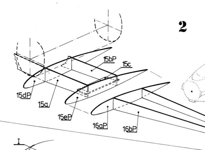 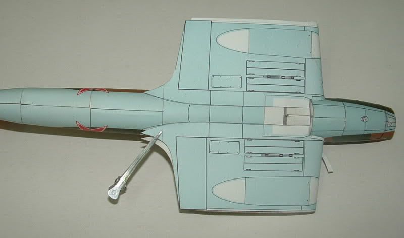 As can be seen there is a gape, that was corrected by cuting it and bonding the part againe with a small angle. 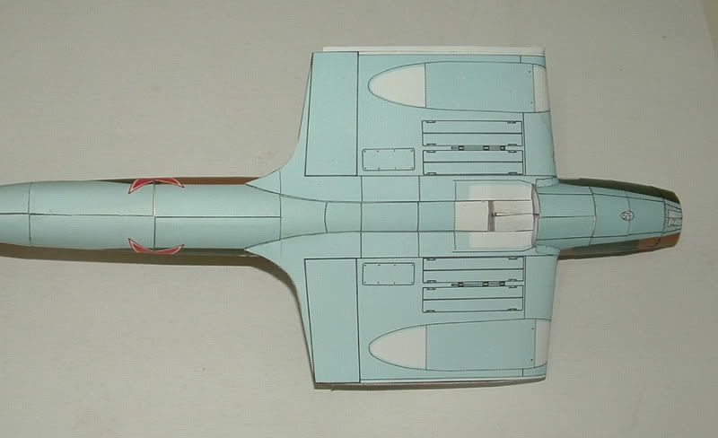 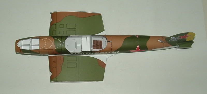 The fairings were bonded first to the fuselage with emphasis on the written slogen. only after it dry the other side was bonded. 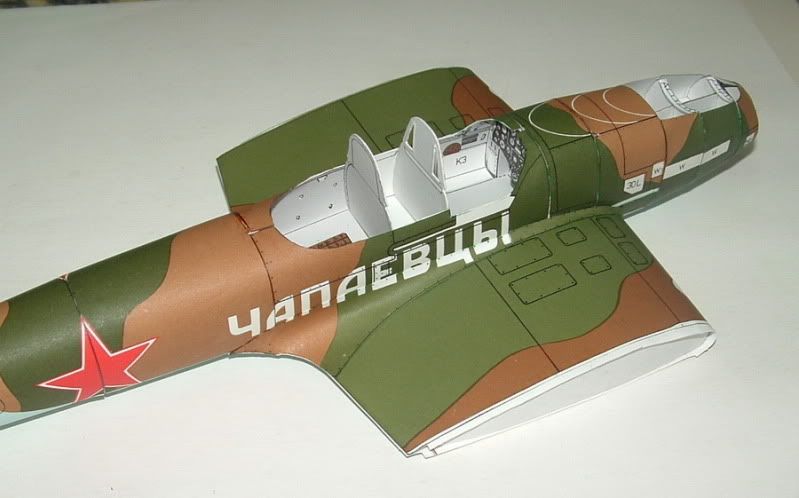 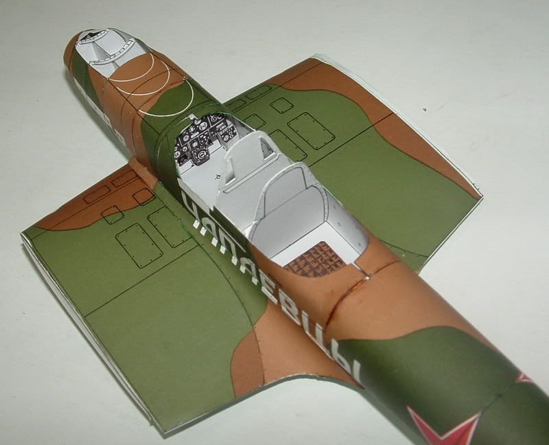 Aircraft has a span of 46cm, so at the moment planing to continue building it without the outer wings as long as I can. 
|
|
#12
10-01-2011, 11:46 AM
|
||||
|
||||
|
Your construction is a good instruction for others. I really appreciate you pointing out gaps and misfits along the way; it's nice to be informed of these issues! You seem to be doing a fantastic job of making it all work so far. This looks wonderful!
Chris
|
|
#13
10-15-2011, 11:00 AM
|
|||
|
|||
|
Hi all,
This time it's tail and radiator inlet. Engine radiator inlet (part 5) is made of two parts as seen in the instructions. To install it I had to depen the cut in the formers (04, 03), and to do some small adjustments to part 1. 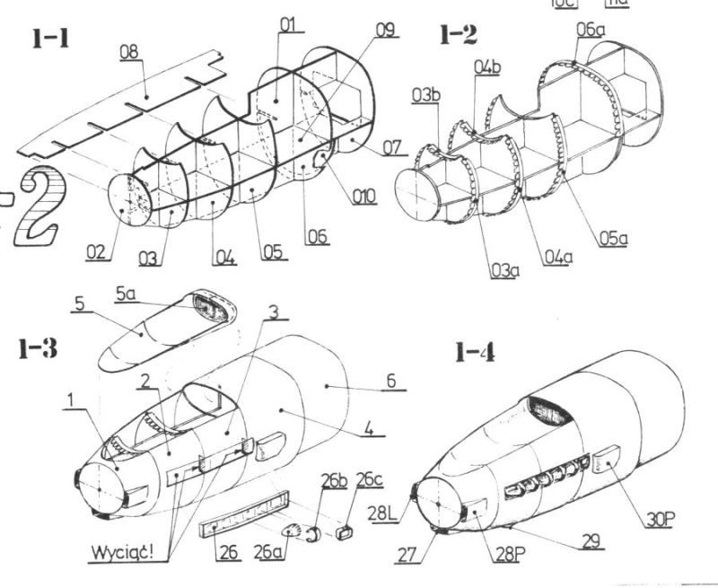 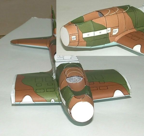 Horizontal tail and the inner stifners were done and bonded. The fairing was bonded at the top, and the lower part cut at the line between the two colors, and will be bonded separately. 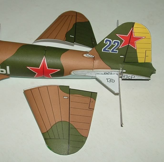 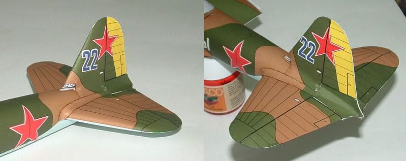 The vertical tail front fairing is smaller than required, and I will have to replace it. 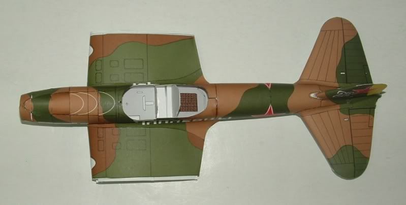 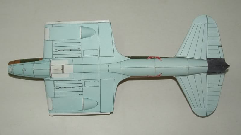 The close up pictures sertainly uncover some areas that need to be painted. Last bottom part (black area) is missing because I was "smart" to painted the inner surface with a black marker that damaged the blue painting. Started to look at details of the maine landing gear bays, and it looks that it needs some detailing and scratch building.
|
|
#14
11-12-2011, 03:58 AM
|
|||
|
|||
|
Hi all,
For now I am concentrating on the maine landing gear's wheels. The model provided a basic design, with no detailing of the wheels inside the wings. 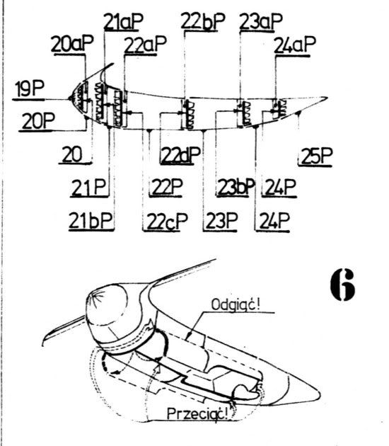 The two next pictures (from the internet) gave a good understanding how wheels should be, first looking forward, and seconed to the rear. 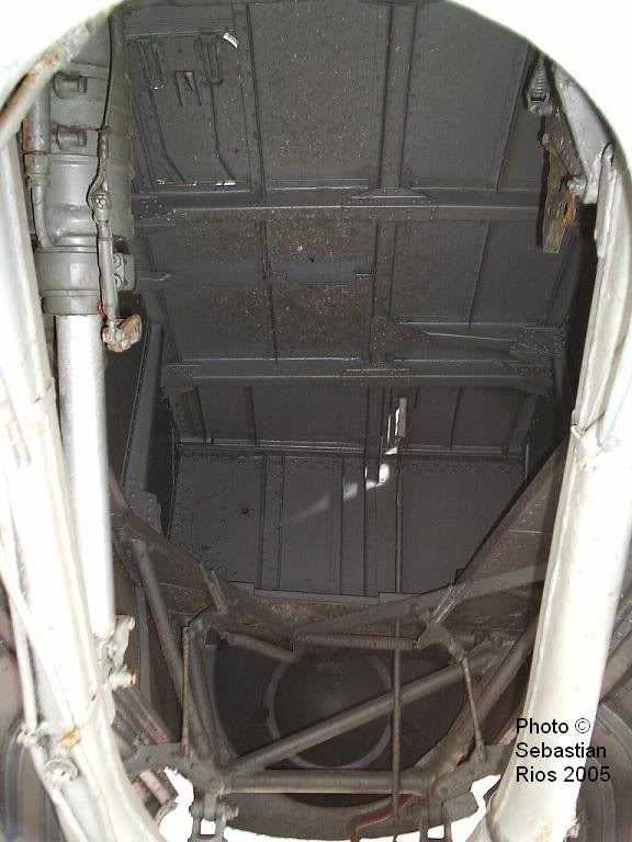 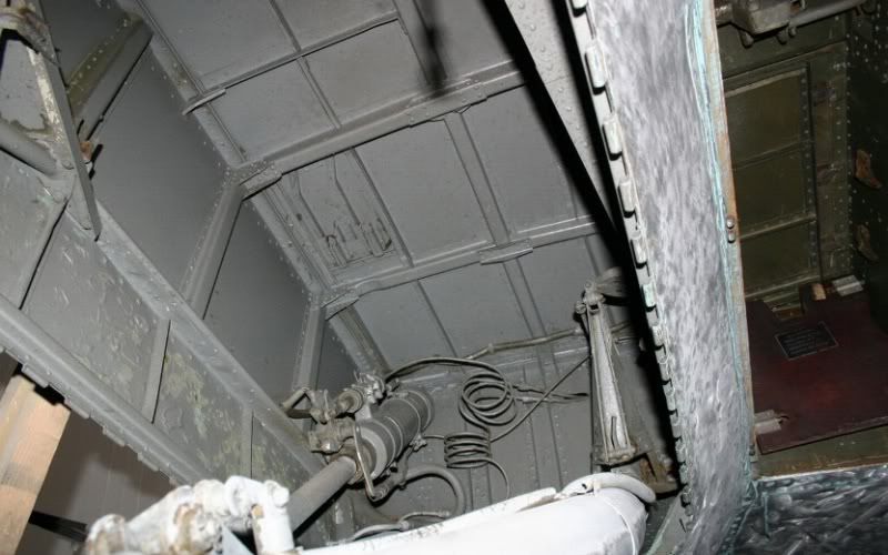 First step was to cut the wings at this area, and some ribs need to be removed. The wheels bay was done from one part, with marks for internal longerons locations. 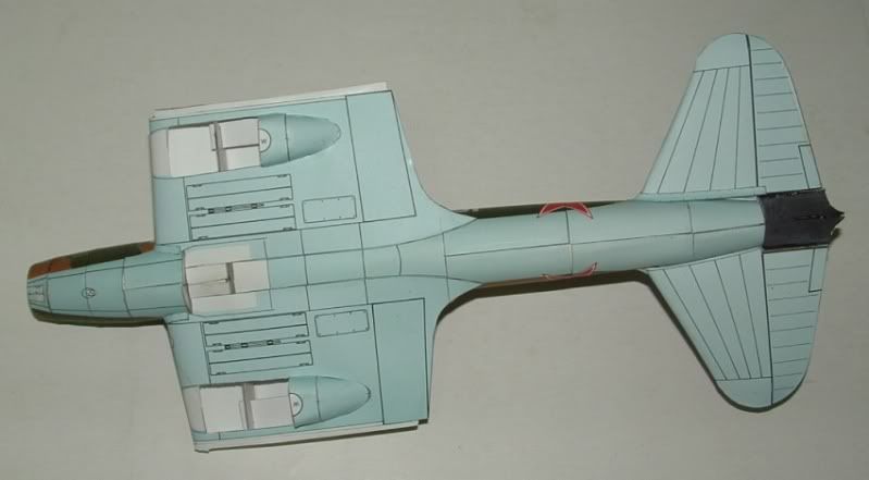 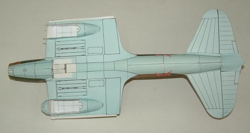 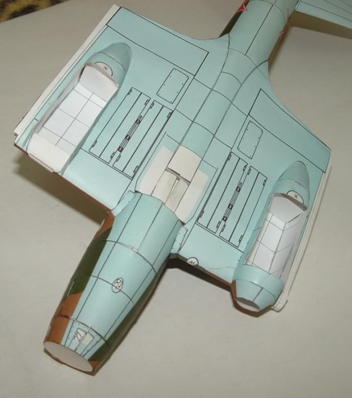 For the longerons I used a very flexible soldering wire. 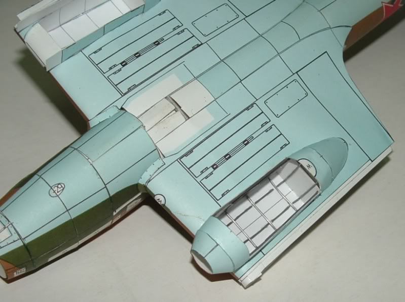 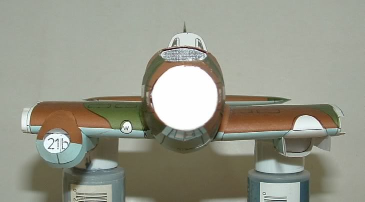 The radiator was done and bonded. Some more detailing need to be done, as seen from the next 2 pictures. 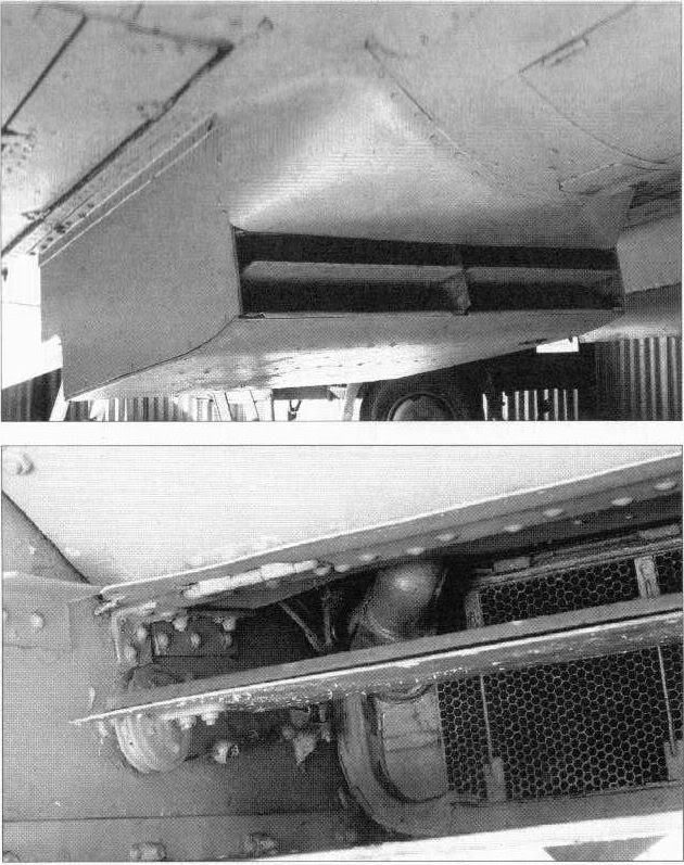 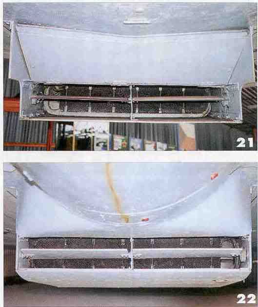
|
 |
|
|


 Linear Mode

