


|
|
|
#51
 10-12-2016, 04:31 AM
|
||||
|
||||
|
Quote:
Dave; I believe that if you look under the seat on that prototype for your rover you'll find a box of unused USB and Firewire cables. Perhaps a couple VGA cables. After all, we do have to stay firmly on topic, don't we?
__________________
Christian
Bristow 
|
|
#52
10-12-2016, 04:16 PM
|
||||
|
||||
|
No modeling last night, but I had a little time before a meeting tonight to get the chassis remade. I emphasized flatness this time and it's looking much better. I'll be playing catch-up for a little while, but that's OK.
|
|
#53
10-12-2016, 05:14 PM
|
||||
|
||||
|
Back to the Fenders and Wheels, its time to attach the four Wheel assemblies.
Each wheel is glued in place to the ends of the downward angled Control Arms. theres no fancy way to do this. And axles won't work because of the offset angle of the suspension. Just apply some glue to the center axle point of the Hub and press to the marked location on the Control Arm. 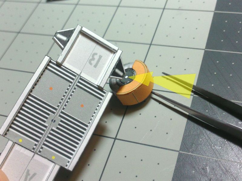 ... Try to line up the Wheels and fenders horizontally and try to keep the wheels as vertical as possible. Adjust (down) the angle of the Control Arm until it lines up with the wheel. 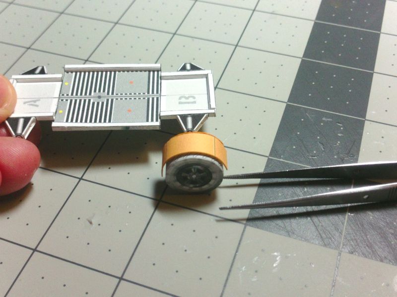 ... Tthe Fenders are supposed to be mounted horizontally...or close to it. Its okay it they are not perfect. We can call it Racing damage, right? 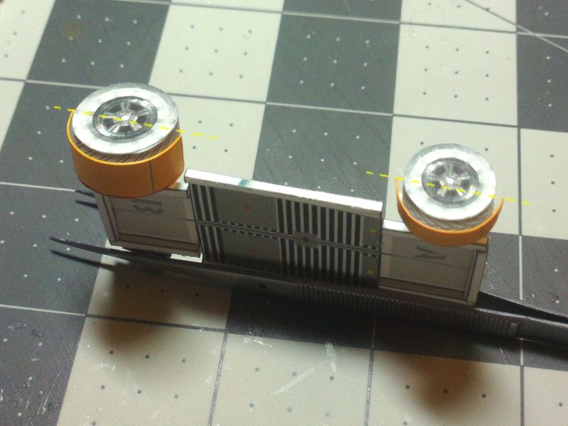 ... Suspend the chassis...allow the glue at the Wheel connection to setup before you put weight on it. The Wheels should mount vertically or have positive camber*...*spread out at the top. They should not have negative camber, so adjust the Control Arm angles if necessary. 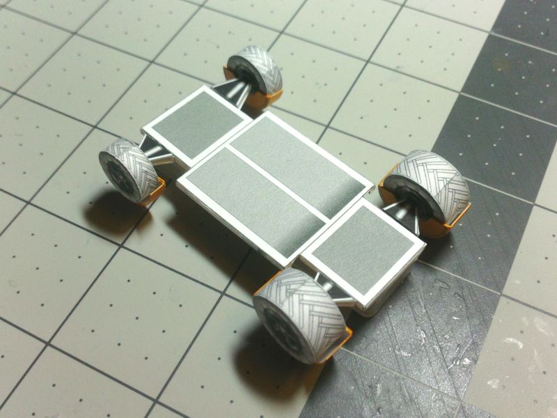 ... 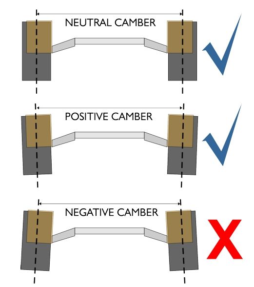
__________________
SUPPORT ME PLEASE: PaperModelShop Or, my models at ecardmodels: Dave'sCardCreations
|
|
#54
10-12-2016, 05:14 PM
|
||||
|
||||
|
And...back to the seats again...cut out the Driver's Racing Harness.
The original Moon Rover did not have seat belts ...but NASA (National Aeronautic StockCar Assn.) demands safety equipment for the driver. 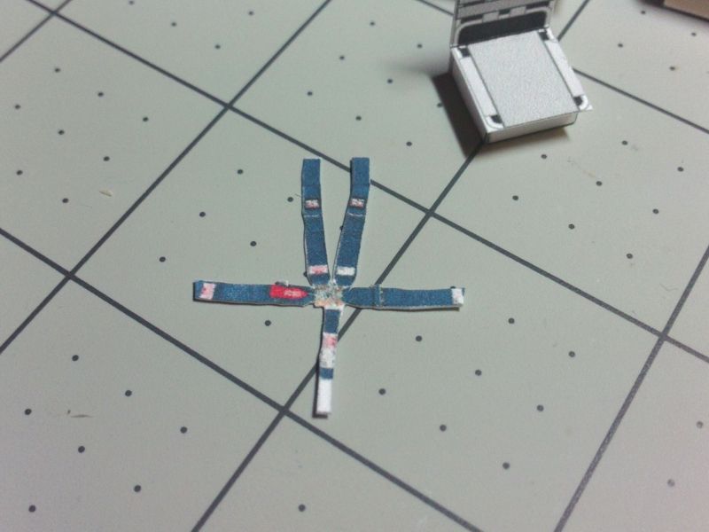 ... Edge colour and fold the top mounting areas. 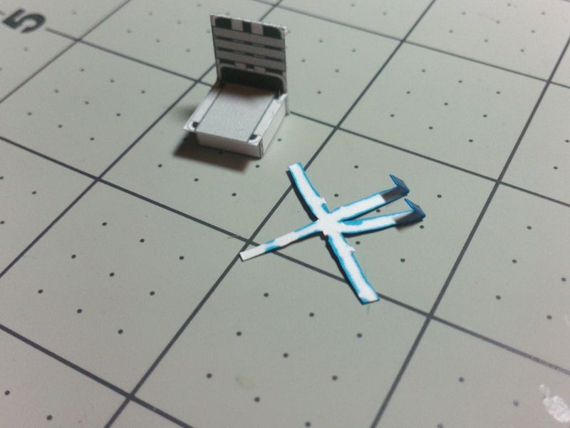 ... Glue the top flaps to the driver's Seat. 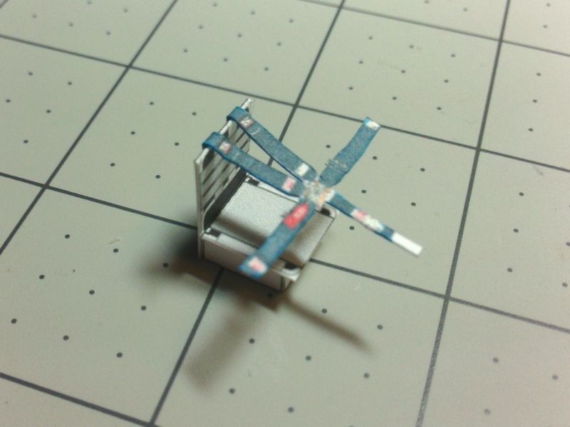 ... Fold down, locate and glue the ends of the lap belt to the sides of the seat base. 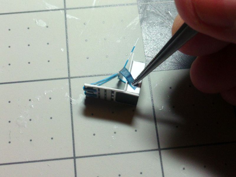 ... Push the center of the harness into the seat and then fold down the center strap and over the front edge of the seat. 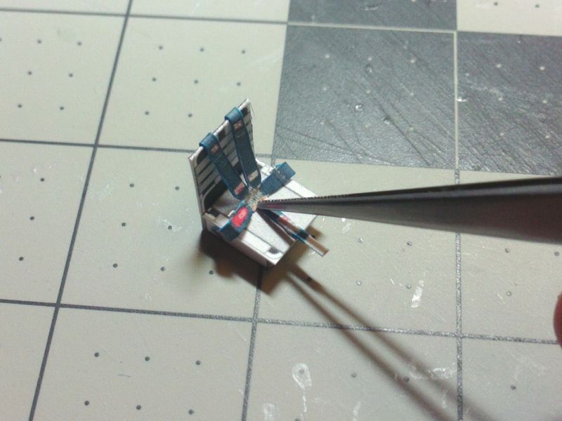 ... Glue the front strap to the seat base. 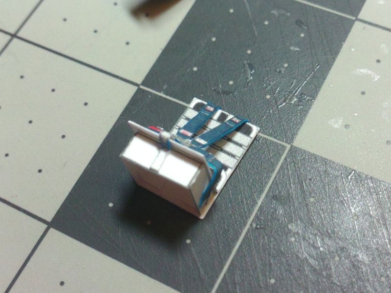 ...
__________________
SUPPORT ME PLEASE: PaperModelShop Or, my models at ecardmodels: Dave'sCardCreations
|
|
#55
10-12-2016, 05:15 PM
|
||||
|
||||
|
Fit the right (Passenger) Seat to the vehicle, by gluing it at the marked floor panel area.
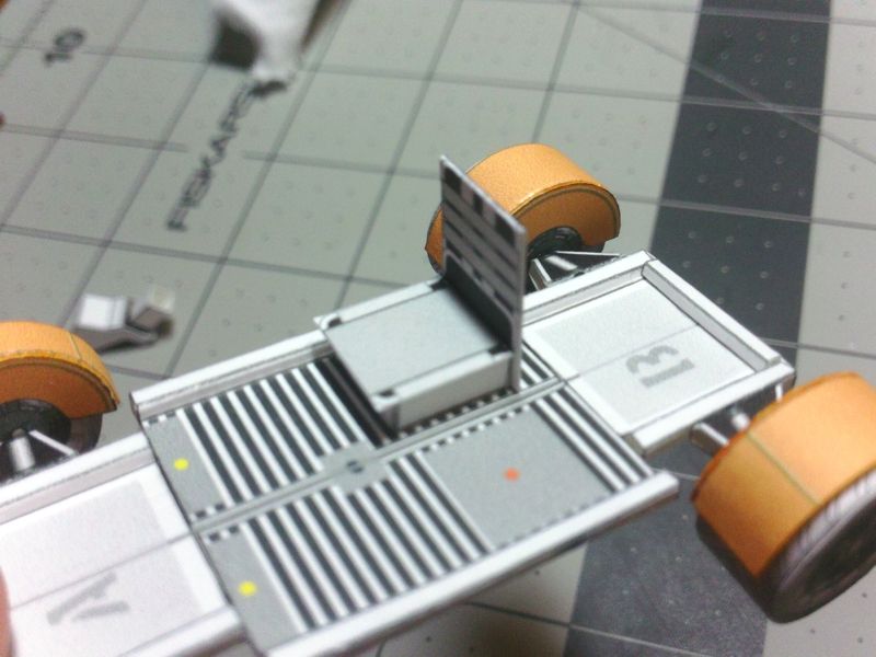 ... Mount and glue the Center Console to the marked location on the floor panels. 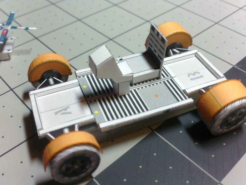 ... Locate and glue the Driver's seat into the left marked location of the floor panel. 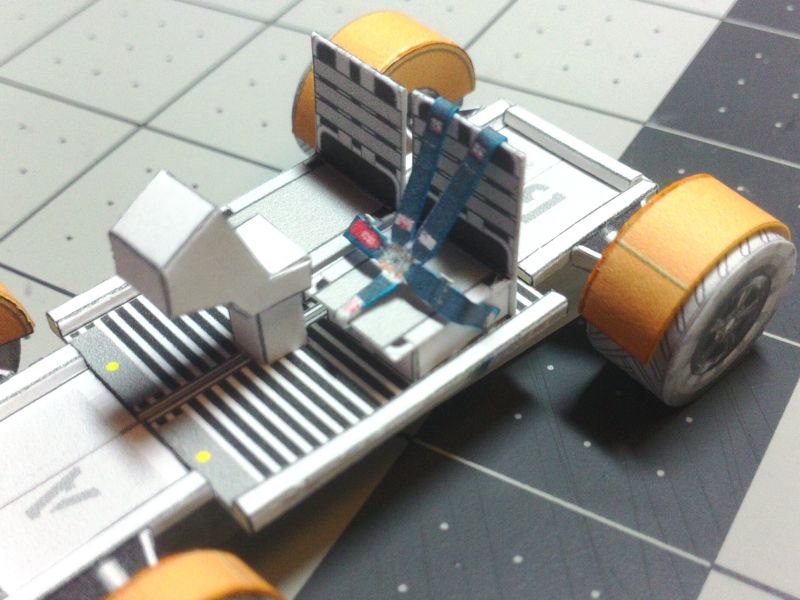 ... Find the Foot Rest parts....already scored... 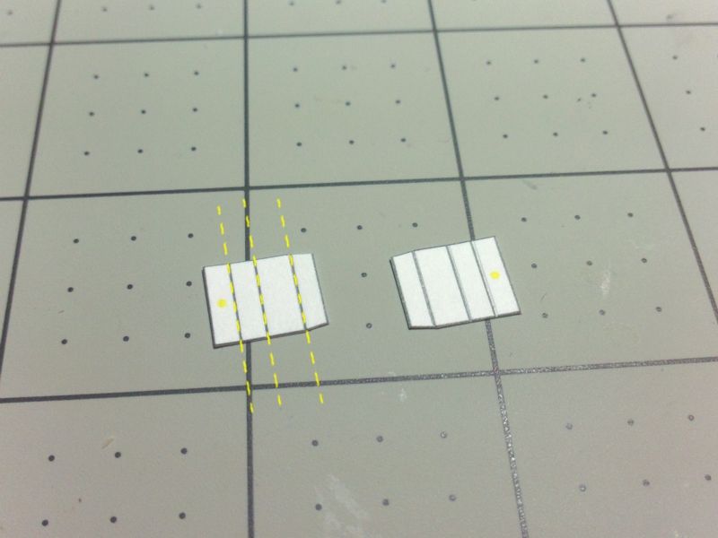 ... Fold and glue into a triangle tube. Note the one wider side panel (the top/foot rest) and the marked side (the bottom/mount side). 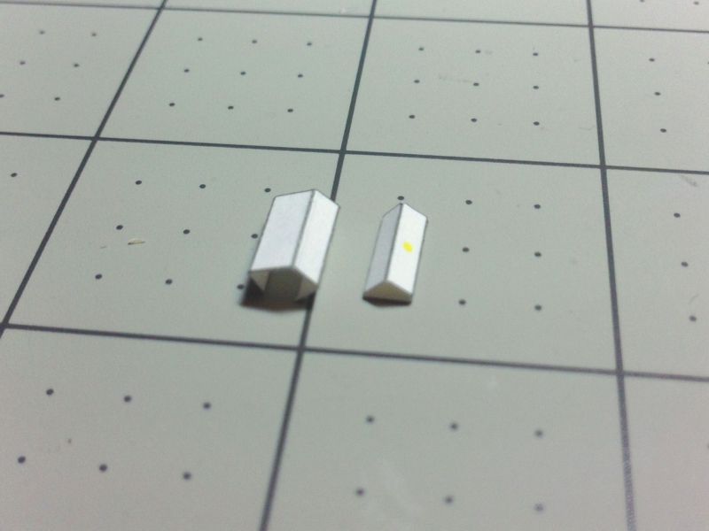 ... Locate and glue the two Foot Rests into place at the marked locations on the floor panels. And, glue the Driver's Seat into place (at the marked location) 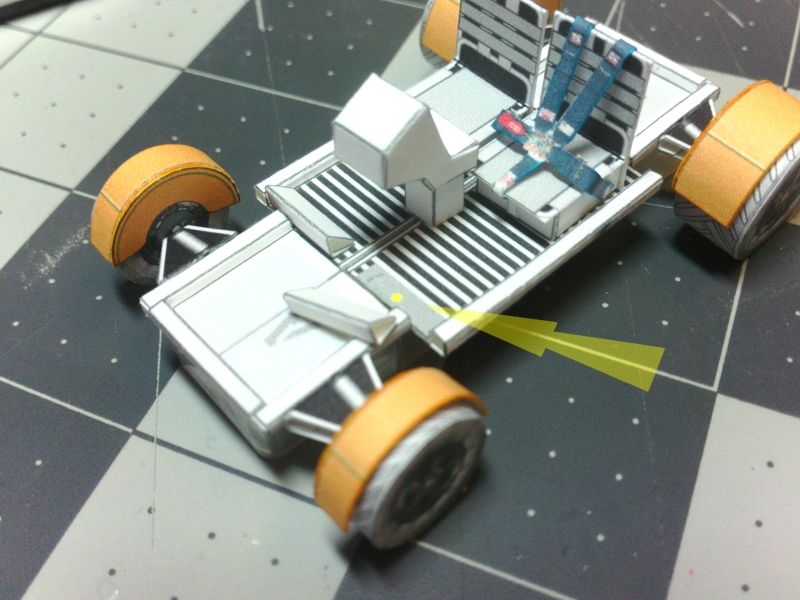 ...
__________________
SUPPORT ME PLEASE: PaperModelShop Or, my models at ecardmodels: Dave'sCardCreations
|
| Google Adsense |
|
#56
10-12-2016, 06:18 PM
|
||||
|
||||
|
Dave can you take a heads on photo so I an see how much the negative camber looks like. Thank you very much. wc
|
|
#57
10-12-2016, 06:56 PM
|
||||
|
||||
|
I posted a drawing that illustrates it exactly.
It shows the approximate downward angle of the control arms and it shows the acceptable positions of the wheels. You're putting too much importance on it. As I suggested, your wheels should be vertical or close to it. But if they're not vertical, then Positive Camber is acceptable. Not Negative Camber. I don't care how much... its all for vehicle height and ground clearance. The wheels glue flat to the ends of the Control arms. The control arms angle downwards, lifting the vehicle higher than the wheels. That downward angle also causes a little bit of Positive Camber. Don't fight it by gluing the wheels at an angle. Don't allow the control arms to rise. If the arms are not angled down, then the wheels will get negative camber. And that means the chassis will sit too low.
__________________
SUPPORT ME PLEASE: PaperModelShop Or, my models at ecardmodels: Dave'sCardCreations
|
|
#58
10-13-2016, 07:50 AM
|
||||
|
||||
|
Dave, one thing you didn't point out was the directional treads on the tires needing to go the same way.
__________________
A fine is a tax when you do wrong. A tax is a fine when you do well.
|
|
#59
10-13-2016, 08:59 AM
|
||||
|
||||
|
ahh... Good point. Something I forgot all about!
So... all but one of my tires are backwards. LOL Do as I say, not as I do. Those who can...do. Those who can't...teach It matters not what you do, as long as you are the best one doing it. Learn from the mistakes of others. You can't live long enough to make them all yourself. Practice makes perfect, but nobody's perfect, so why practice?
__________________
SUPPORT ME PLEASE: PaperModelShop Or, my models at ecardmodels: Dave'sCardCreations
|
|
#60
10-13-2016, 11:56 AM
|
||||
|
||||
|
Dave I read and saw your drawings. I just thought if I could see a photo of your model to illustrate the camber head on it would be helpful. That's all. I didn't pay to much attention to the tires and put one on backwards. Easy fix. Thank you Dave for all your help. This is such a great model. wc
|
| Google Adsense |
 |
|
|


 Linear Mode

