


|
|
|
#11
 02-11-2024, 09:31 PM
|
||||
|
||||
|
@Doug I took a look at the drawing and I see two areas that need to be modified from P-40E to P--40N: the canopy and the rear fuselage, which is longer than it should be.
I can modified these for you if you'd like and It won't take long
__________________
Buy me some coffee at https://www.buymeacoffee.com/thaipaperwork Visit our Online shop at https://thaipaperwork.wixsite.com/onlinestore or https://www.buymeacoffee.com/thaipaperwork/extras 
|
|
#12
02-12-2024, 05:11 PM
|
|||
|
|||
|
Nobi,
I sent an email with a few references for the P-40N-5. I believe this is the variant Lt Adair flew with the Burma Banshees. Doug
|
|
#13
03-16-2024, 03:50 PM
|
||||
|
||||
|
Question on nose assembly
Nobi
I am working on your model of the 23rd Fighter Group P-40E, which, because of your excellent design, is going together well in spite of my lack of skill. However, I cannot figure out how to attach the nose radiator (Part 7). Specifically, I do not understand the purpose of the tabs circled in orange in the attached image. It seems to me that the front end of the model will only go together if I cut off those tabs. Any advice would be greatly appreciated. Best wishes, Don
|
|
#14
03-16-2024, 04:50 PM
|
||||
|
||||
|
Hi Don. Nobi is often busy so I'll answer.
I'd cut them off. They are meant to be bend inside the radiator and used to hang/ glue radiator housing to fuselage. Imho they are more trouble than worth it but some people like tabs and they ( sometimes )are good clue what side of the part gets glued. They can be always cut off. What I'd like to see is bottom of white test model build by Nobi. Picture please?
|
|
#16
03-16-2024, 06:10 PM
|
|||
|
|||
|
Karol beat me to it. I dont have this one completely glued in place yet, it is part of yet another Doug amble down the path of the obscure and underrepresented, but the part fit is going very well.
I had to shave off a bit on the top of parts 8 and 10 while I was dry fitting, almost certainly due to my lack of skill in initial cutting. Itis amazing how much of this airframe was the engine and that radiator scoop. Most educational for me is how quickly the fuselage narrows once you get behind the cockpit. Doug
|
|
#17
03-16-2024, 06:54 PM
|
||||
|
||||
|
How I make parts like this radiator: when cutting part from page I cut edges of radiator that join to fuselage a wee bit longer, say two thicknesses of black outline longer. I glue the entire radiator either with tabs provided or separate ones glued behind joint. I insert radiator face into housing and dry fit it on fuselage (they are very often too large). When dry fitting that excess material comes handy because since it's white it serves as a better visual guide to make part symmetrical left and right side of the engine. Once correct length and position is found excess material is cut in one shot, edge is colored with pencil and part glued.
Intake should look like this. 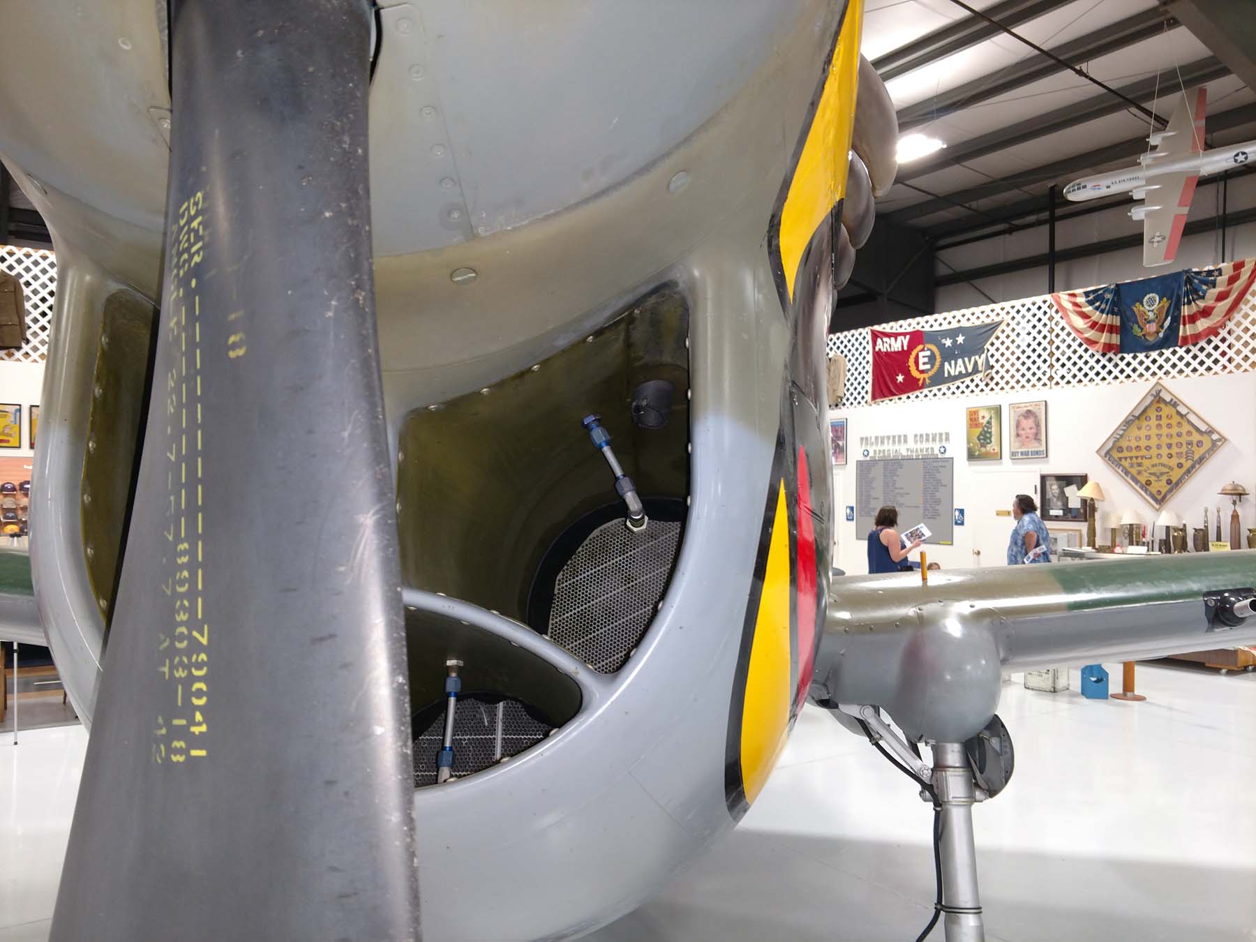
|
|
#18
03-16-2024, 10:16 PM
|
||||
|
||||
|
Thank you very much for all the responses from those who answered on my behalf. I apologize for any confusion caused. In reality, I should have labeled part 11 as part 7, as you may need to assemble part 11 with part 6 first. The tabs are meant to help secure parts 6, 11, and 7 together.
The correct steps should be: 1. Reinforce part 6a* and attach it to part 6. 2. Assemble part 11 with part 6. 3. Reinforce part 8* and attach parts 9 and 10 to it. 4. Assemble part 8*+9+10 with 6a*. 5. Assemble part 7 with part 6+11.
__________________
Buy me some coffee at https://www.buymeacoffee.com/thaipaperwork Visit our Online shop at https://thaipaperwork.wixsite.com/onlinestore or https://www.buymeacoffee.com/thaipaperwork/extras
|
 |
|
|


 Linear Mode

