


|
|
|
#91
 08-26-2013, 12:05 AM
|
||||
|
||||
|
Hi all together,
so up to the corner of the Side 1 I had come already with the LOX-Vent line, 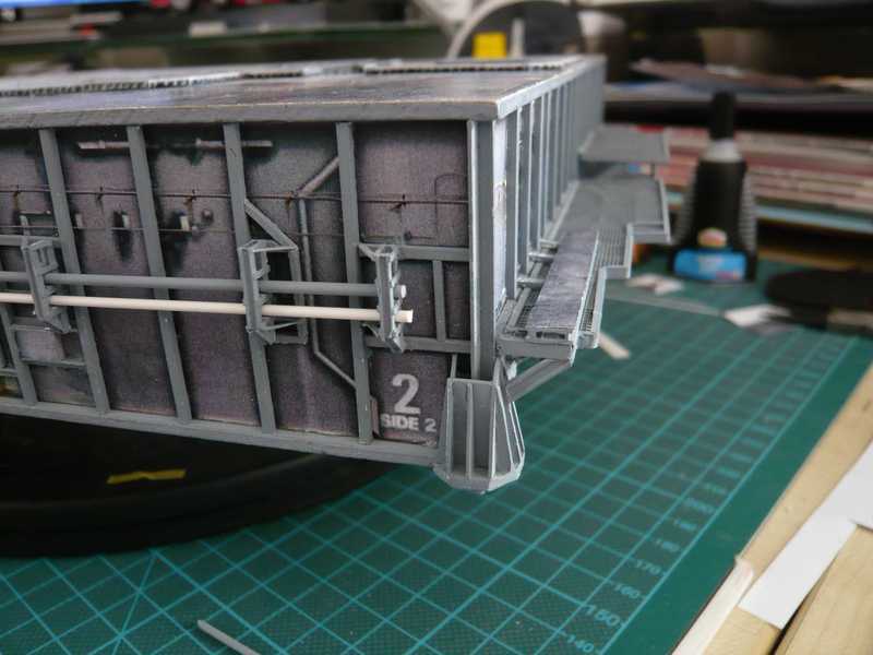 But this corner it has in itself. There an Expansion joint sits in front of the corner and immediately the next following after the corner on Side 1, unfortunately it is difficult to see. 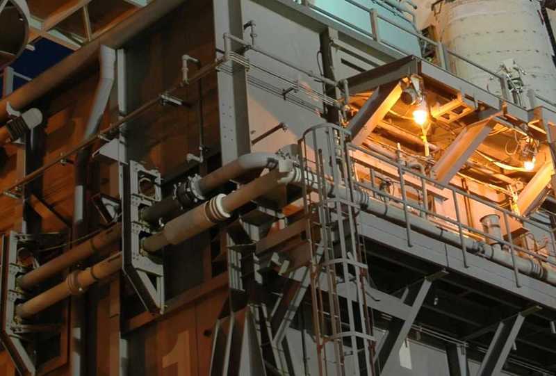 Source: NASA This corner is just critical for the stability of the pipes run, that's why the two pipes are held by an appropriately stable and several reinforced corner-pipe support, which is better to see in this photo. 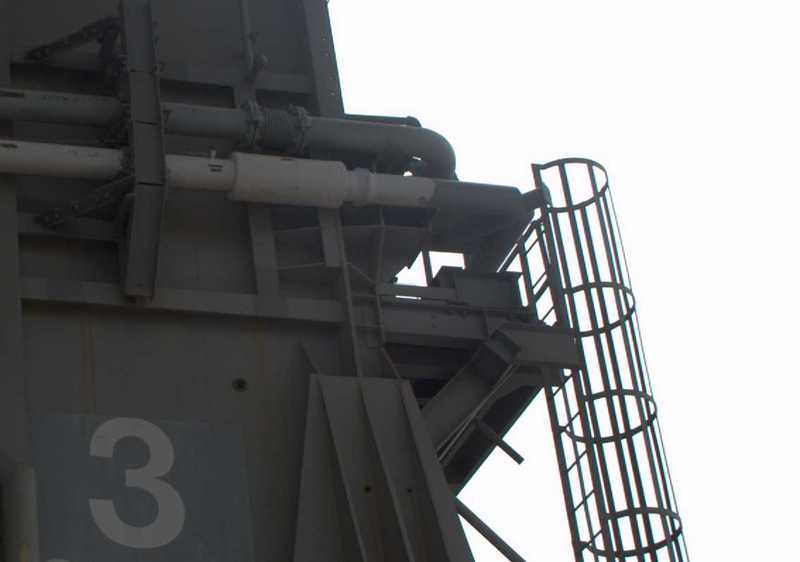 Source: J. Patterson (NASASpaceFlight.com) What is more, that the white Transfer line at this point also has a critical section in the form of a weld, which sits under the sleeve below the expansion joint of the Vent line. In the paper kit, the bracket is only done by this small and only one side printed (why?) Pipe support LH6, which I will omit and therefore better scratch-build. 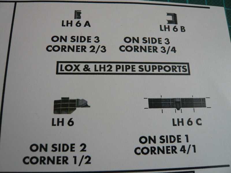 Therefore I looked for longer time on different photos the constructive version of the corner support, in order to correctly detect and then somehow scratch-build it. Conceptually he is constructed similar like the corner support at the corner of Side 2 to Side 3, only he uses forward through more honeycomb-like sticks continues, because the Transfer line further extends over the corner as the Vent line. So again a pretty tricky task of Ervergreen strips and sheet. :  These are the five wedge-shaped struts from 0.2 mm sheet left sitting next to the corner angle profile. 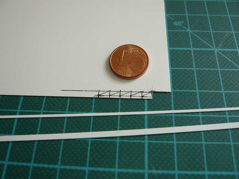 And here they are already glued and have received a final cover strip of Evergreen strip 1,0x0,2 mm. The start has been made, and now it can go further with this honeycomb-like structure on the right side. 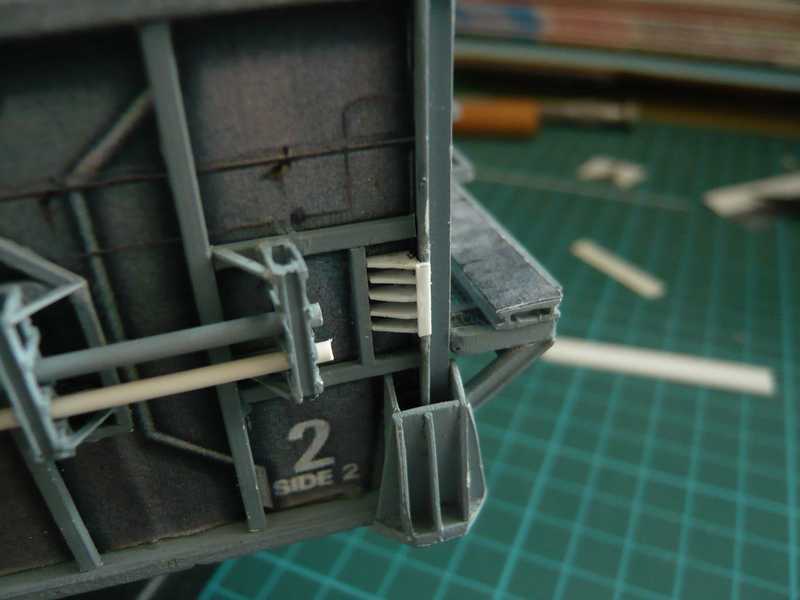 Now the struts on the right side of the angle profile and beyond were added. These are such small puzzle particles, you can capture that hardly with tweezers without having it jump one of.  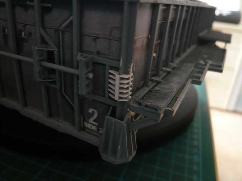 Here an impression of the size of the particles, the lower triangle with a length of about 1 mm, which was swabbed with superglue and then as far as possible placed in the first step into the right place. And then it sticks either there where it belongs, or to the tweezers.  And now the lateral plate is glued on the struts. 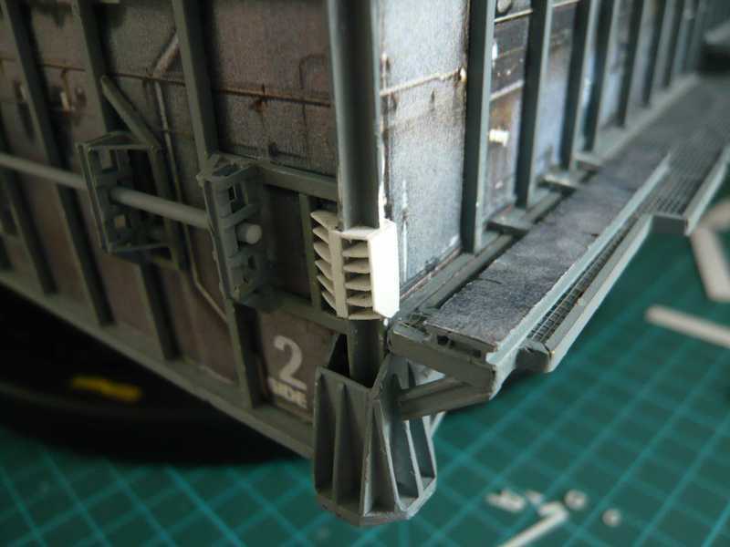 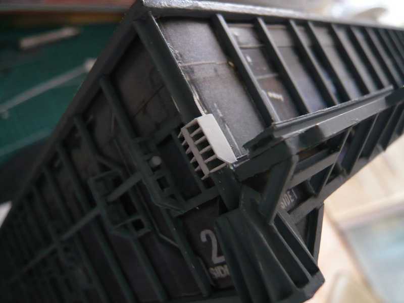 And here comes now a further small building on it. First the struts for mounting the bracket of the Transfer line were glued. 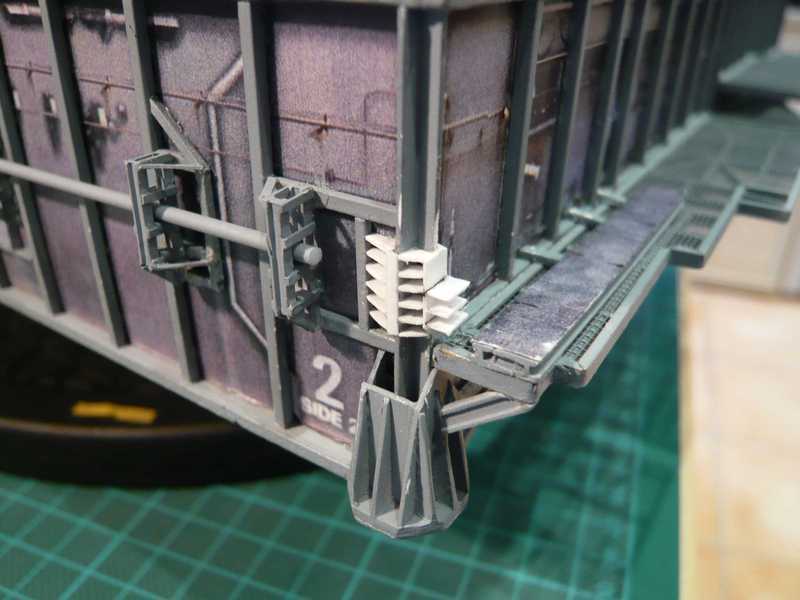 On the struts, the plate is mounted now actually, what the bracket sits. It is prepared already, and just I wanted to glue it already on the struts, but since dropped me a just in time that it would be probably better once to paint so far left building, as it could be otherwise may be difficult to get behind with the brush still in the small holes. So, the previous support was painted first. And that was actually better than I thought, of course with a very fine brush. 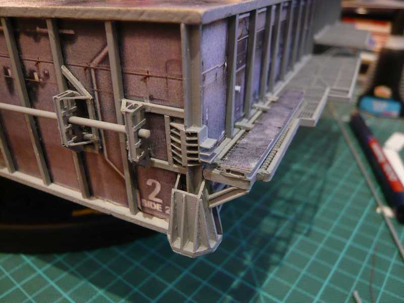 Next the bracket for the Vent line was prepared from an Evergreen strip 2,0x0,25 mm, which was filed on 1.8 mm in width and suspended on a trial basis, to identify the required length and the supernatant of the bracket. 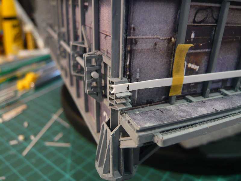 Then the bracket was painted. While the paint dried, the already painted plate on the struts was glued now. After the Transfer line was inserted same time to the fitting, to determine their location and distance from the support. 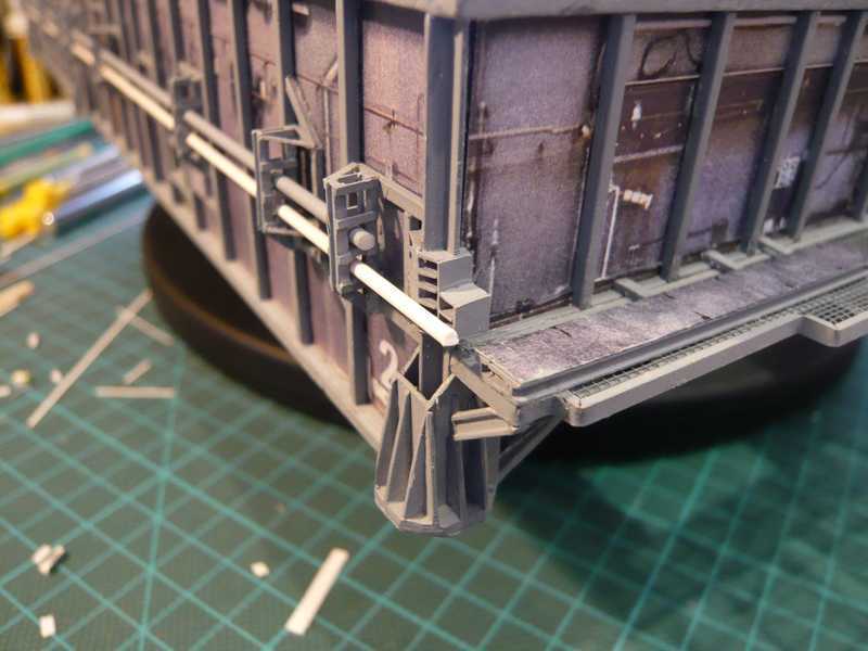 The Vent line bracket was then glued on the rear plate. 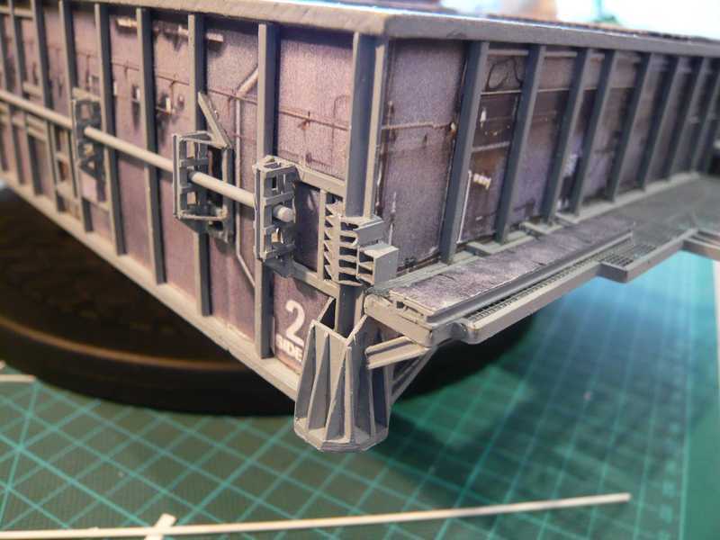 The bracket for the Transfer line is similar to and then tomorrow comes on the front bottom. 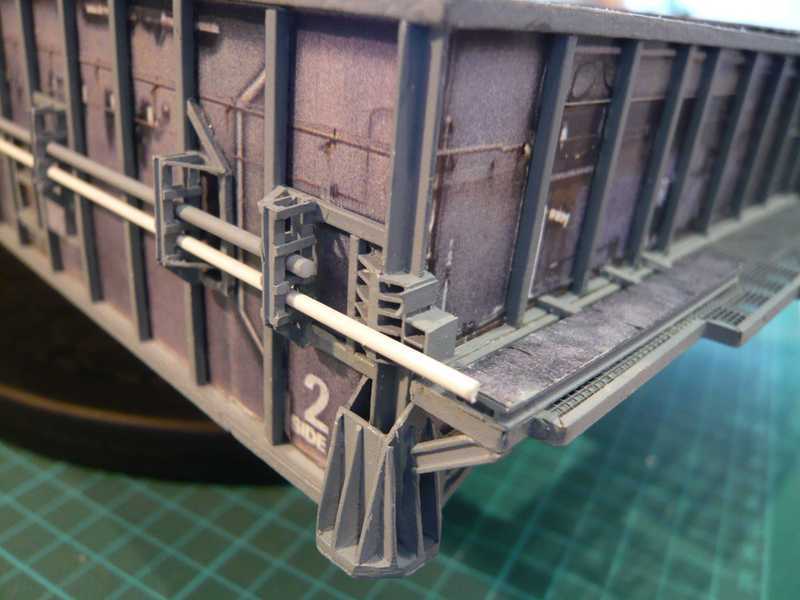 As far as for today. 
__________________
Greetings from Germany Manfred Under construction: Launch Pad 39A with Challenger STS-6 (1:144) Last edited by spacerunner; 10-12-2016 at 04:46 PM. 
|
|
#92
08-27-2013, 12:54 AM
|
||||
|
||||
|
And here is the next update.
It goes on with the lower bracket for the transfer line, as a supplement, 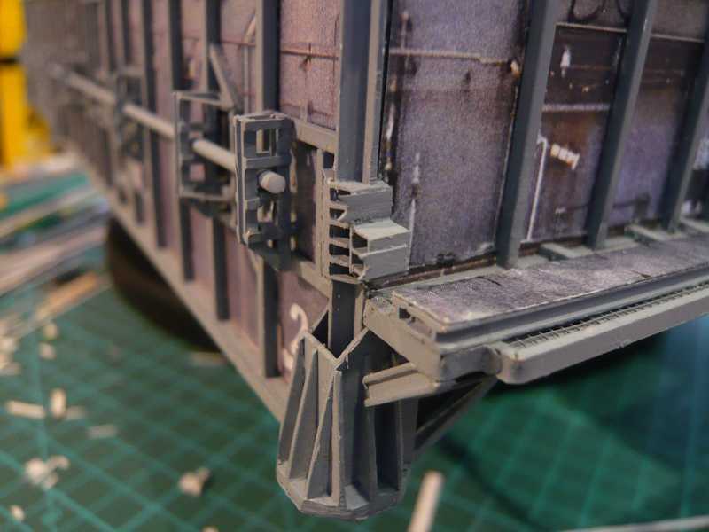 and then the fitting of the provisional transfer line that fits quite well. The final pipe is the arch but not round, but is still segmented. 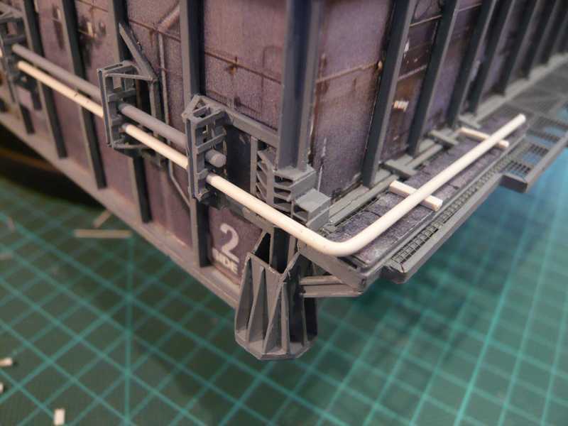 Next I have planned now the alignment of the vent line in Bay 1, starting with the third and final Expansion joint on the Side 2, directly behind the stub, and then around the corner on Side 1 goes further, where already the next expansion joint follows. 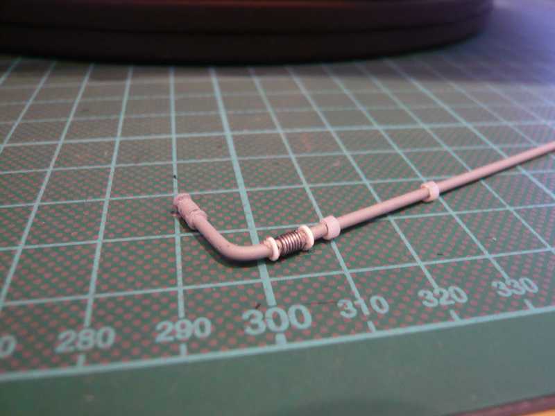 Right next to the prepared expansion joint is already the bearing cups sitting on the pipe supports of the vent line on the left pallet. I had that cut from a plastic tube (Ø 2,75x1,6 mm). 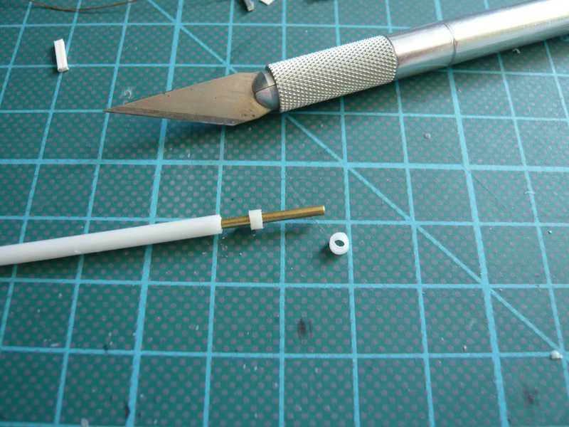 Here the pipe are as reminder again to see the pipe supports with the bearing cups in the original:  Source: http://www.capecomespace.net And here is the vent line as fitting to the pipe support installed. Since one must watch out that fit the gaps and matches the level of the connections, and this looks already not bad, both on Side 1, 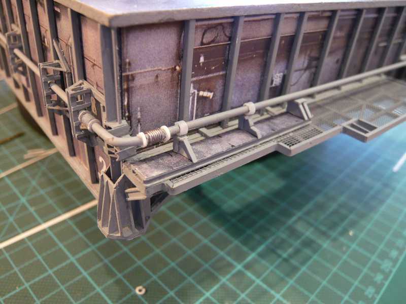 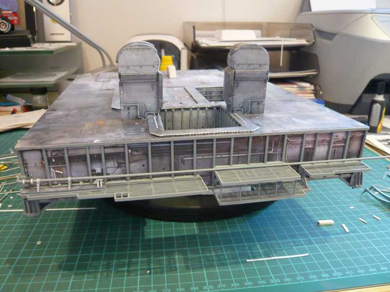 and Side 2. 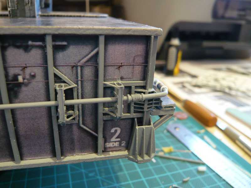 So, the rest of the Vent line can now go to the painting and then be mounted. Then, only the reinforcement angles in the arches of the pipes missing as here to see in the picture with the arrows. 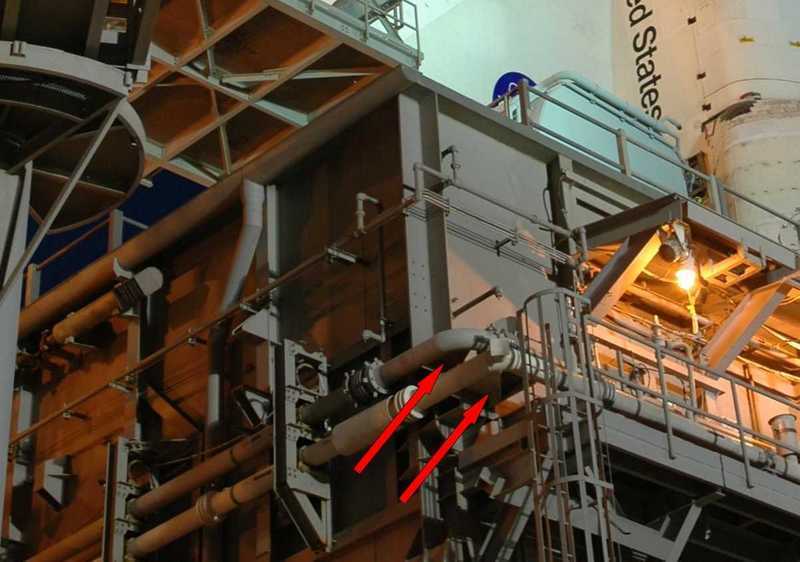 Source: NASA And next time it will continue with the Transfer line on the Side 2, starting again at the corner-pipe support at the end.
__________________
Greetings from Germany Manfred Under construction: Launch Pad 39A with Challenger STS-6 (1:144)
|
|
#94
08-27-2013, 11:42 PM
|
||||
|
||||
|
Hi David,
nice to meet a singer-songwriter this way, who is also interested in Real space modeling!  But for a plumber license I have surely gather much experience, but by and by it is getting better.  The Right Graduate waiting on the Side 1 on me when it comes to the Access platforms with the LOX and LH2 Valve skids with all their pipe madness, as you will see.
__________________
Greetings from Germany Manfred Under construction: Launch Pad 39A with Challenger STS-6 (1:144) Last edited by spacerunner; 10-12-2016 at 04:49 PM.
|
|
#95
08-28-2013, 12:29 AM
|
||||
|
||||
|
Hi all together,
the pipe men have really not easy time and only had to wait for the painters which had taken a few vacation days more! But now the tube bend of the vent line around the corner on the Side 2/Side 1 has been painted at last and could be installed immediately after fitting the pipe supports.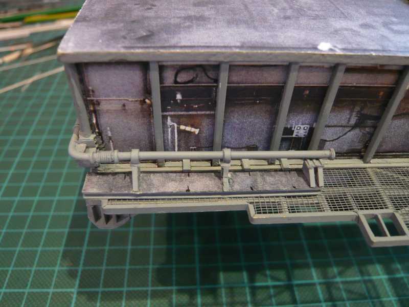 This is now not so much business, but at least, with small steps to get to the destination too. 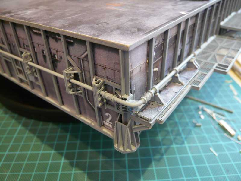 This is, as I said, the critical corner between the two Expansion joints, which is why in the tube bend of the vent line extra still a stiffening angle was welded, the just yet as can be seen. Right, this line section of the vent line reaches until to the end of Bay 4, where a drain hole is located, which is sealed with a blind flange. 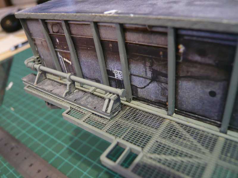 At this point, there is a branch line in the vent line, from which it then goes to the LOX-Valve skid with the LOX-Filter, as shown here in the picture. 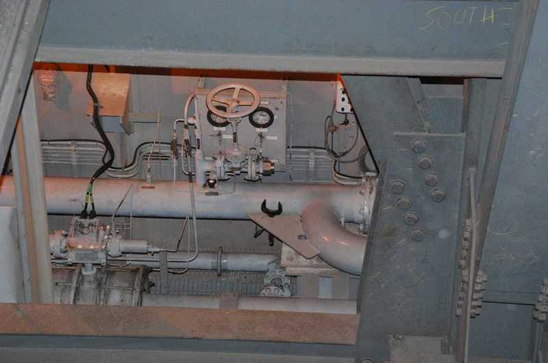 Source: J. Patterson (NASASpaceFlight.com) This is in the following picture the place directly behind the right green arrow over the local pipe support. 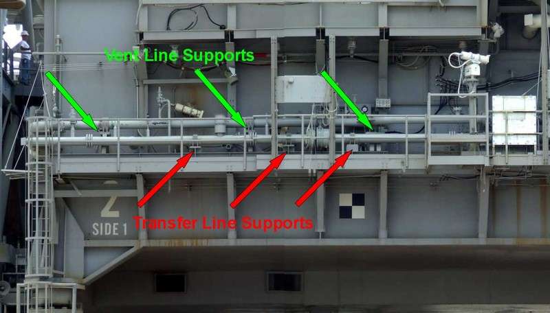 Source: NASA These pipes want to take seemingly no end ...  But once more back to Side 2, there is still something to scratch, exceptionally no pipes and no pipe supports, but the two Pneumatic vent mufflers in Bay 3 and Bay 4, here once again to the memory in the picture. 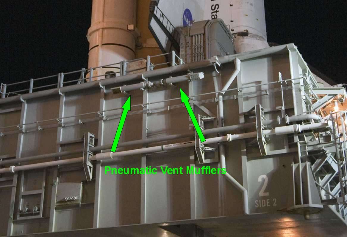 Source: NASA Since this is only a continuous tube in the paper kit, I've scratch-built it again as well as already the four vent mufflers on Side 4. First I attempted to glue the side brackets from Evergreen strips 0,7x0,2 mm directly onto the paper tube, but that did not glue on, as the adhesive surface is just too low for pasting. 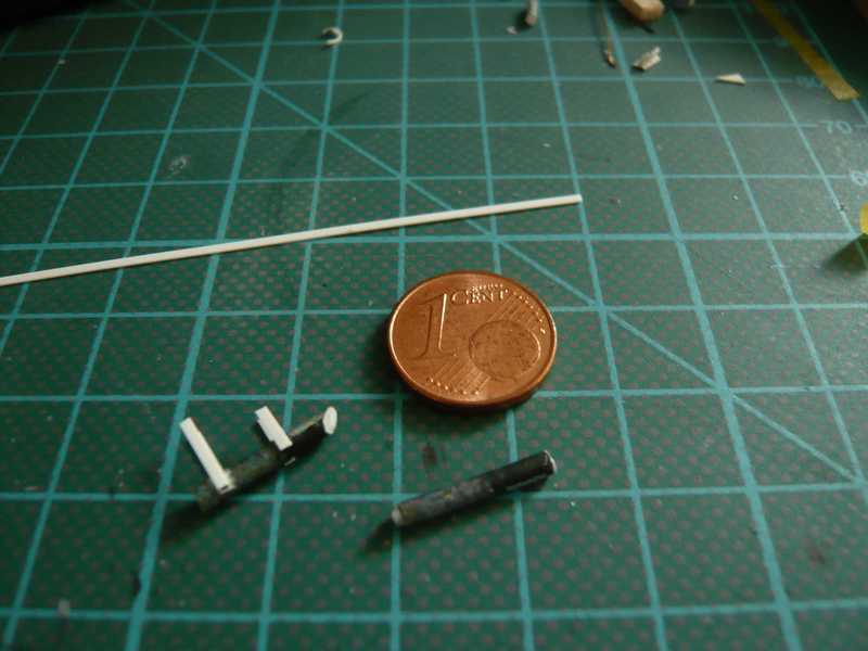 That's why I had to try another option, which I have stuck the side brackets at an I-beam 2,4x1,2 mm, what has glued better. 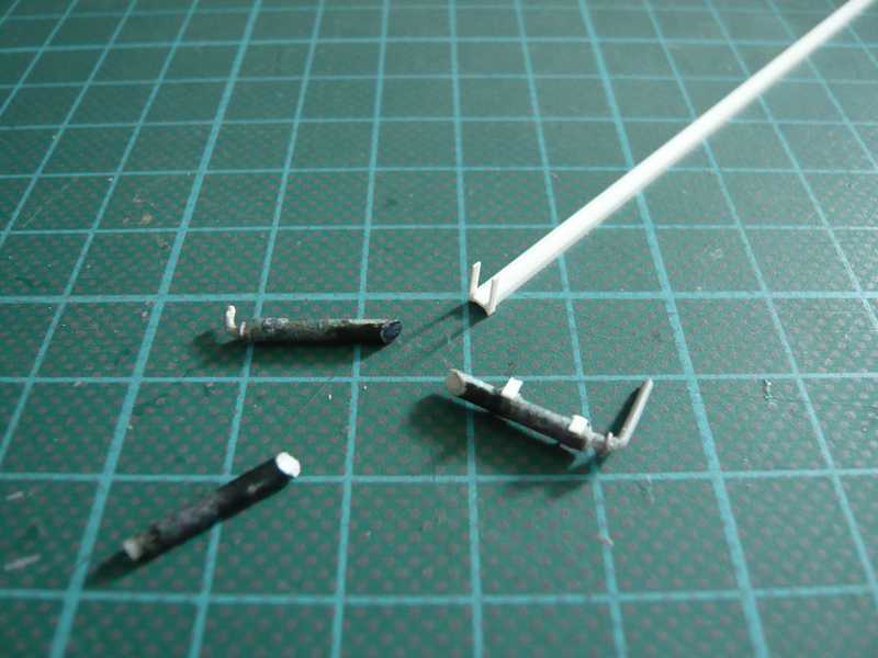 It then created these filigree mountings. The service pipes are again from 1 mm round profil and the connection clamp was indicated with 0.3 mm lead wire. 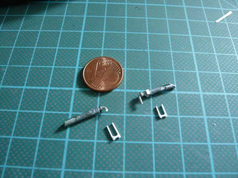 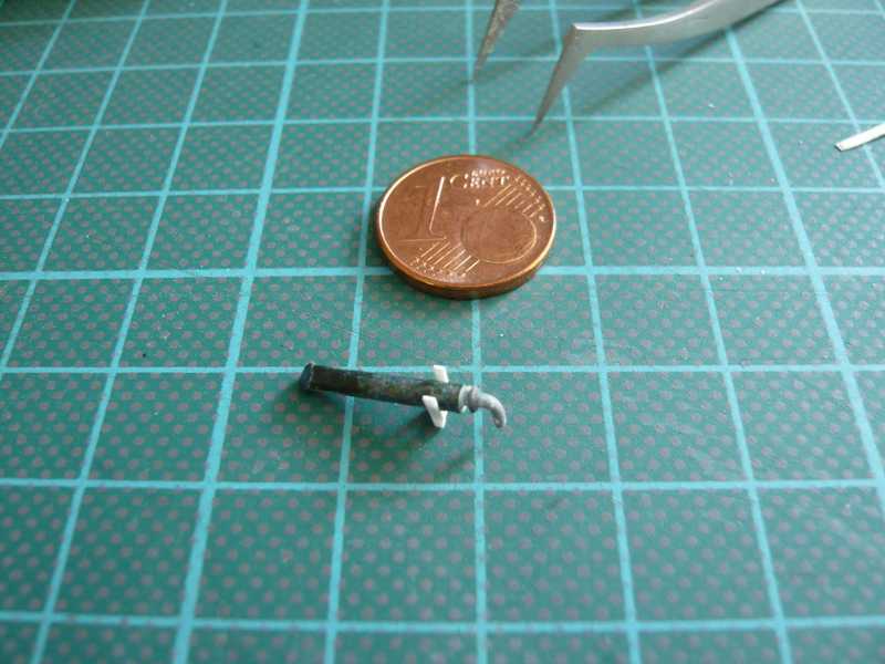 And here the vent mufflers are already on their place and have got a second couple holding footbridges. 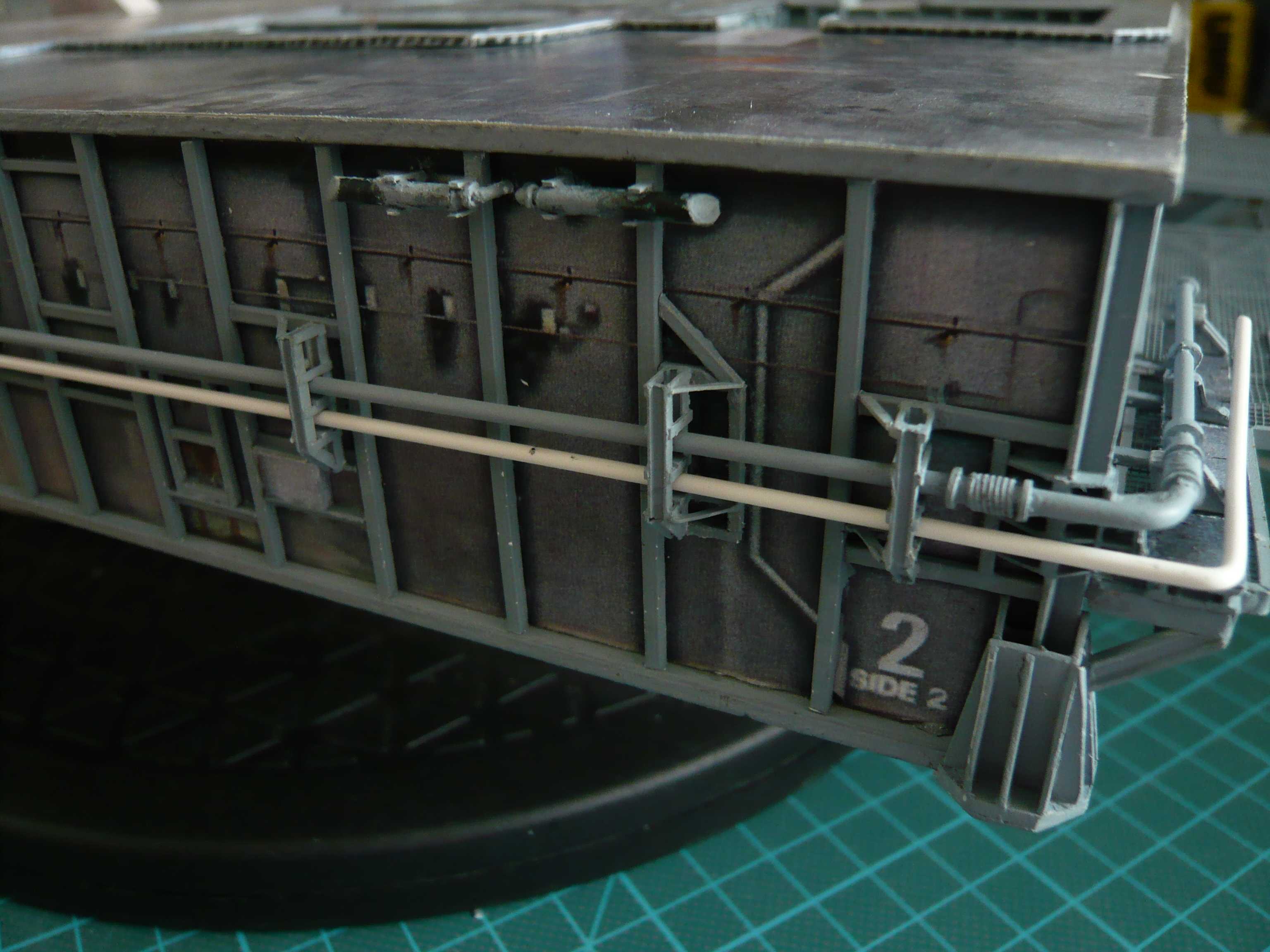 These are again only small details, but anyway would be done again.
__________________
Greetings from Germany Manfred Under construction: Launch Pad 39A with Challenger STS-6 (1:144) Last edited by spacerunner; 10-12-2016 at 04:50 PM.
|
| Google Adsense |
|
#96
08-28-2013, 04:33 AM
|
||||
|
||||
|
I was just checking in Manfred...looking great! Superbly done. How did you get ahold of those good pictures? Are they public domain?
Bill
__________________
----------------------------------------------- Seems to have been Deliberately Buried ----------------------------------------------- Where did Gunter Wendt ? 
|
|
#97
08-28-2013, 06:47 AM
|
||||
|
||||
|
Thanks Bill, most of them are public domain from NASA sites, and some pics I've privately got from friends.
If you want to scratch build special details you need good pictures, the best close-ups. And for the search you have to sacrifice lots of T I M E ... 
__________________
Greetings from Germany Manfred Under construction: Launch Pad 39A with Challenger STS-6 (1:144) Last edited by spacerunner; 10-12-2016 at 04:53 PM.
|
|
#98
08-28-2013, 07:28 AM
|
||||
|
||||
|
Friends????
As in you mean "astronaut" friends? I know fighter jocks....( my nephue... an F-15c pilot ) but no spacemen!
 Bill
__________________
----------------------------------------------- Seems to have been Deliberately Buried ----------------------------------------------- Where did Gunter Wendt ?
|
|
#99
08-28-2013, 08:35 AM
|
||||
|
||||
|
I know some of the "Pad rats" from the NSF Forum who were very close to it ...
__________________
Greetings from Germany Manfred Under construction: Launch Pad 39A with Challenger STS-6 (1:144) Last edited by spacerunner; 10-12-2016 at 04:54 PM.
|
|
#100
08-29-2013, 07:05 AM
|
||||
|
||||
|
After the Pneumatic vent mufflers it's time now for the corner support for the LH2-Pipes at the corner of Side 3 to the Side 4, which looks like different than its counterparts at the previous corners. Fortunately it is built not as complicated as the honeycomb-shaped support on the corner Side 2/Side 1, but at least similar to that on the corner Side 2/Side 3 for the LOX-Pipes.
Here the two parts of the support are relatively easy to see on the MLP-2: 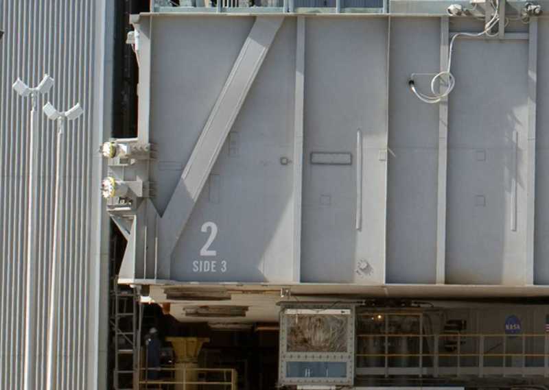 Source: NASA Because the two LH2 pipes are relatively far apart at the end Side 4, at this corner there are two separate supports without a common base plate like at the other corner of Side 3. These are nuances, which did not immediately fall one right off the bat. And these supports differ somewhat in the construction by MLP to MLP. And this is a lot of the parts you need for both support. And as you can see already, they are very small and therefore the installation will become probably somewhat stressful: 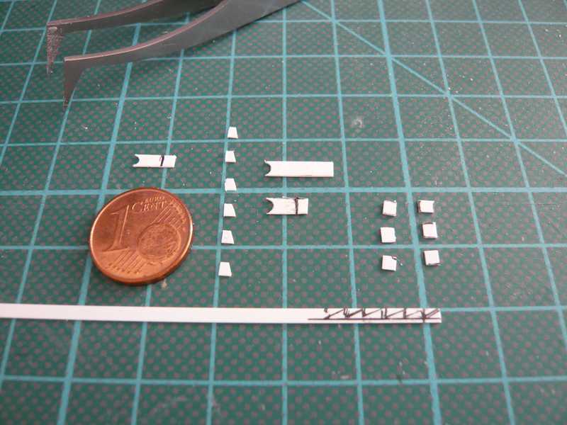 But now you get a certain feeling for parts in the mm range, and already it started again with the bonding of the small bars around the corner angle profile. 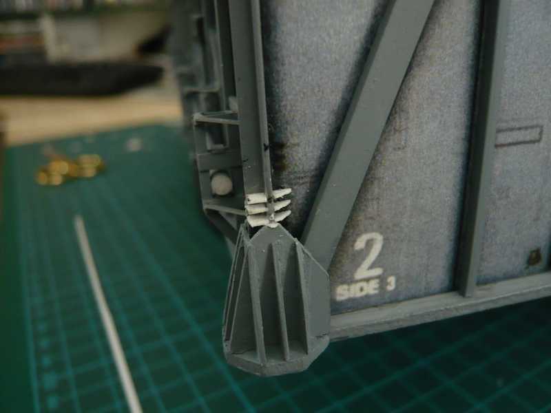 First on Side 2, and then around the corner and up to the Side 4. 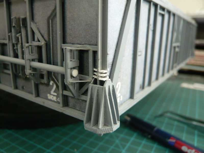 And behind the 1st pipe bracket the construction of the bars for the LH2 vent line goes on up to the 2nd bracket. And similarly the upper support of the LH2 transfer line is built, which has only one pipe bracket. 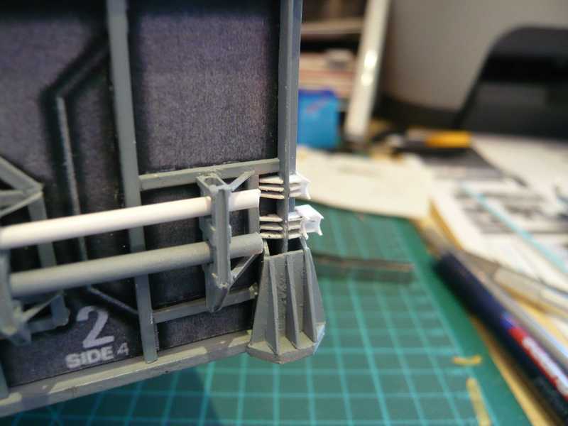 And then both supports were painted yet. 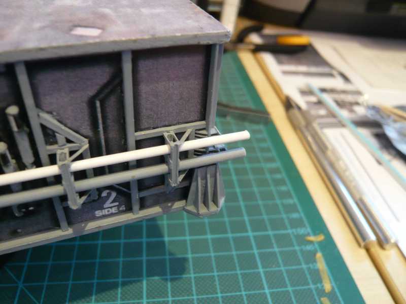 The supports are hardly to see behind the pipes. 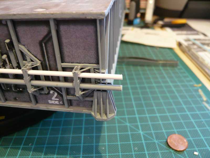 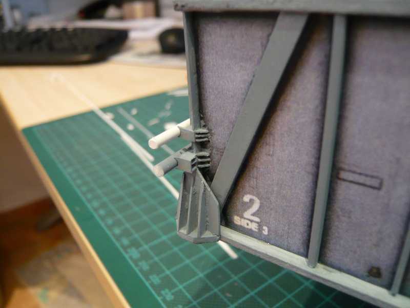 Now missing only the stiffening angle to the upper support, that can be glued only after mounting the transfer line with a segmented pipe bow. Next follows the insallation of the LH2 vent line with its three expansion joints in the same way as on the Side 2.
__________________
Greetings from Germany Manfred Under construction: Launch Pad 39A with Challenger STS-6 (1:144) Last edited by spacerunner; 10-12-2016 at 04:56 PM.
|
| Google Adsense |
 |
|
|


 Linear Mode

