


|
|
|
#1041
 05-14-2016, 10:07 AM
|
||||
|
||||
|
Hello everybody,
before the "sharp" bending of the 24'' ring line (Ø 4 mm) around my new Balsa Template I first made a few draw tests under hot air stream in order to get a feel for.  And as one can see, this is quite feasible, the only problem is to produce the desired diameter of the taper at the right place. The taper in the left image is from Ø 4 mm to Ø 2,3 mm. With simultaneous defined bend it is then more difficult to produce reproducible dimensions and arches.  Therefore the use of the two-component modeling compound Apoxie Sculpt appears to be almost more promising, especially for the outgoing pipes and transitions. And I wanted to try out this alleged superweapon already longer.   Here we go. These are the two components A (right) and B (left), which must be thoroughly mixed together in the ratio 1:1, so that the mass is well hardened after 24 hours.  Both components are doughy, so that one can form two such marbles according to need,  and kneads them with each other intense such a long time,  until one gets a uniform mixed color. Only now one can process the mass within about two hours, therefore do not panic!   Now the mass is spread almost like dough and can then be modeled to one's heart's content, either flatten with fingers or even work on with special spatulas, whereby occasional moistening is advisable and useful.  Excess material can be removed or missing material be adapted, nothing is impossible within two hours. Since the remaining material is unfortunately waste, one should assess its needs as well as possible in advance what is not yet succeeded to me, as you can see.   And then one should leave things alone to dry for 24 hours before one is possibly thinking about reworking by grinding, should this be necessary.  And I'll be watching tomorrow closer.  
__________________
Greetings from Germany Manfred Under construction: Launch Pad 39A with Challenger STS-6 (1:144) 
|
|
#1042
05-15-2016, 01:11 AM
|
||||
|
||||
|
Hello everybody,
and therefore now to my first impressions of Apoxie Sculpt. This modeling compound is really easy to work with. Once hardened, it is light gray and stone-hard, absolutely tight and free of cracks. I have only yet smoothed something the transitions with a sanding sponge 2000s, that's also already.   It focuses first on this thickening (36'' ≙ Ø 6 mm) in the ring line, in which the 36'' inlet pipe discharges, which is coming out of the chamber's corner.  Source: NASA The shape of the center part is not yet final, because this area is still too long and a little too thin. This part is instead 12 mm only 9 mm long and the diameter 6 mm instead the previous 5.5 mm, but this is finally taken into account in the pipe.  And similarly, it looks at the other side of the line,  where the ring line behind the LOX-TSM tapers from Ø 4 mm to Ø 2.5 mm.  Source: NASA With this result, I am quite satisfied for the moment, so I will most likely remain in this variant. I.e. I'll bend the arched outlets into the shafts via respective balsa stencils and then attach, and then model the transitions with Apoxie Sculpt. I suppose that this way the dimensions and geometries of the outlets will be reproduced better than with the drawing technique.
__________________
Greetings from Germany Manfred Under construction: Launch Pad 39A with Challenger STS-6 (1:144)
|
|
#1044
05-16-2016, 04:36 AM
|
||||
|
||||
|
Thanks Gene for your nice compliments.
 I know it's crazy,  but I can't these details let be. but I can't these details let be.
__________________
Greetings from Germany Manfred Under construction: Launch Pad 39A with Challenger STS-6 (1:144)
|
|
#1045
05-17-2016, 12:53 AM
|
||||
|
||||
|
Hi folks,
today only a few small detail corrections. After careful watching of the T-shaped branch of the 36'' feed line in the shaft corner I noticed that the transitions from the thickening to the 24'' ring line looks slightly different than that of my prototype. As you can see in the photo already shown several times, the transitions run slightly obliquely and concavely,  Source: NASA what I had not initially considered. With me they were even more arched slightly convex. This is not so serious, but the form is not yet correct.  Therefore, I have modified the left side accordingly, and it all looks the same better, I think, because the difference is obvious.  The post-processing went smoothly because the Apoxie Sculpt is so fine-grained and dense that there are no outbreaks. And then still the to another problem, to which I would like to hint now in view of the occasion. This drawing here with the dimensions of SSWS pipes has been indeed shown on several occasions, but a crucial thing always had been neglected. This is the arrangement of the SSWS pipes on the MLP-1 which distinguish oneself from the other two MLP-2 and MLP-3.  Source: NASA And these are the marked arcuate transitions between the SRB-supports and these bows in front of the two TSM's, which does not exist on MLP-2 and MLP-3 in this form.  As one can see in the photo of MLP-1, in particular the rear bows and the corresponding supports are significantly higher,  Source: capcomespace.net while in MLP-2 and MLP-3 all the bows have nearly the same shape and height, although the outlets are different, which I will discuss later.  Source: NASA But I want to point out to the inner outlet once more, which looks at MLP-2 and MLP-3 like this and has other dimensions than I had recently given.  Source: NASA There the end of the 24'' ring line directly tapers into a 12'' pipe, which then leads without further taper into the shaft, what I had not observed previously, especially because the opposing outlet has a taper after the bow. Incidentally, this is clearly evident already from the drawing.  Quelle: NASA But now it's enough with detailed quibbles.
__________________
Greetings from Germany Manfred Under construction: Launch Pad 39A with Challenger STS-6 (1:144) Last edited by spacerunner; 05-17-2016 at 01:38 AM.
|
|
#1046
05-18-2016, 06:25 AM
|
||||
|
||||
|
Hello everybody,
today it goes round, borrowing from an Oldie of The Spencer Davis Group - Keep On "Bending", so everything has been said.  The thick 24'' ring line is on the program, and therefore quick to the work.  The hot air gun is already ready for battle. The hot air gun is already ready for battle. 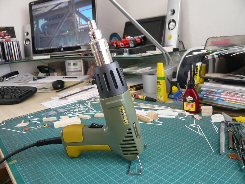 Before starting I still had cut a recess in the template, because the sleeve for the thickening of the pipe must be threaded before bending, otherwise one has a problem, because afterwards it's impossible. 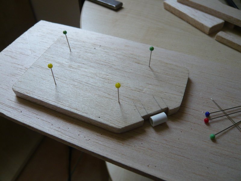 It is important for the bending of the pipe around the Balsa template, that one gives the rod no chance to dodge, so it must "obey blindly." For this one must squeeze him into a stable balsa corset til immediately prior to the bending point.  Then, the bending area is moderately blown with hot air while the rod is simultaneously bent gently until the plastic starts to soften what happens relatively abruptly. Therefore one should then align the rod preferably immediately and over the entire length at the next edge and fix it in this position until to cooling down. And here the handy rod (Ø 4 mm) has got already its first 90° bend.  And if everything has worked well, this bending is virtually "frozen" and also after removal of the corset dimensionally stable. 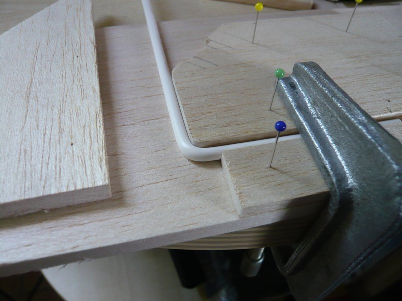 In order for the ring line remains planar during the following bends, because of the sleeve one must not forget previously to underlay corresponding compensating strips.   And then already follows the 45° bending along the slant with the sleeve in the recess.  Then the area for the next bending point is fixed again,  after which the second 45° bending follows. Since the next narrow retaining strip has offered too little support for the last bending, 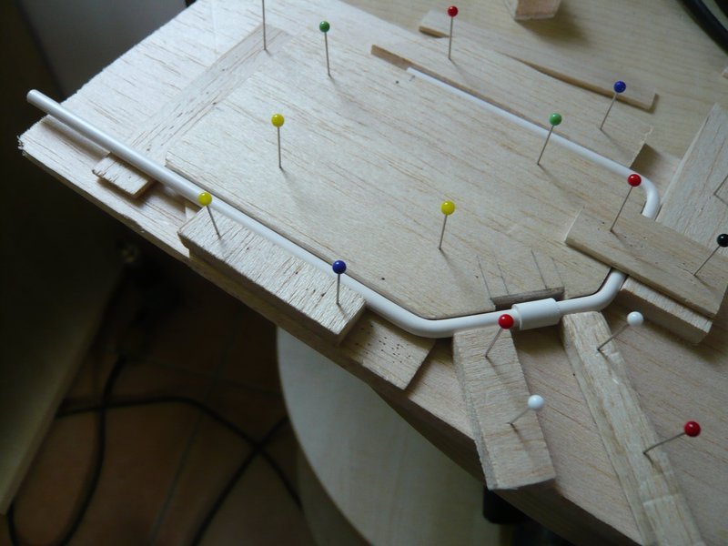 a stronger Balsa board had to be used.  But with it then also the last bending has worked well, 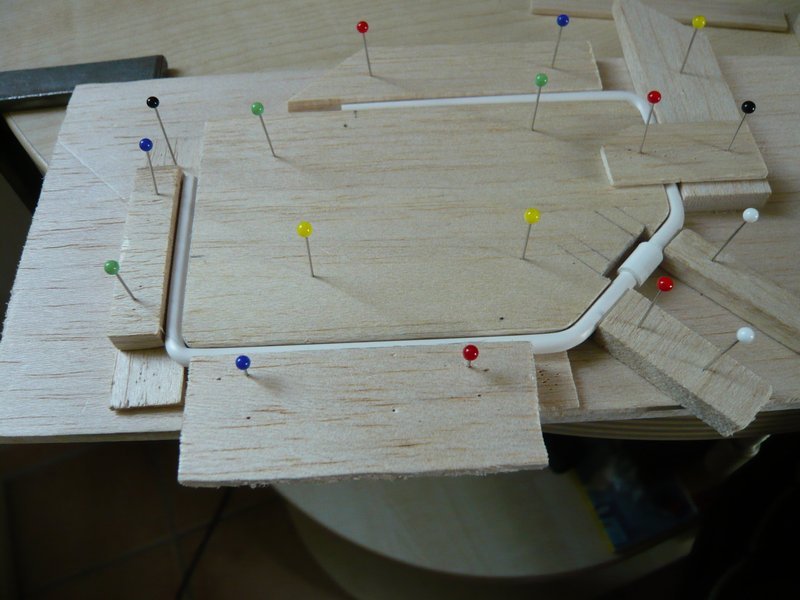 so that the ring line has remained dimensionally stable even after removal of the outer corset rods, what eventually was meaning and purpose of the whole exercise.   Okay, if you look closely, you can see that the last area still has a minimum curvature, which can still be smoothed. 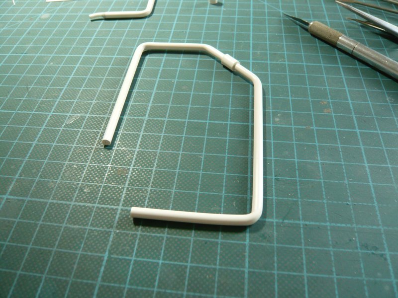 And because everything works the way how I had imagined, I can also quietly bend the second ring line.
__________________
Greetings from Germany Manfred Under construction: Launch Pad 39A with Challenger STS-6 (1:144) Last edited by spacerunner; 09-19-2016 at 03:38 PM.
|
|
#1048
05-24-2016, 05:40 AM
|
||||
|
||||
|
Hello everybody,
before the bending of the second ring line I still wanted to check their position on the MLP, here initially on the sketch, to which it fits very well. 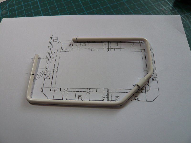 And here the positions of all 20 Pipe Supports are now marked,  whereby the 18 supports for 24'' Ring line (Ø 4 mm) are already finished and waiting for the test, of which there are both some with clamping rings (green) as also without (red). 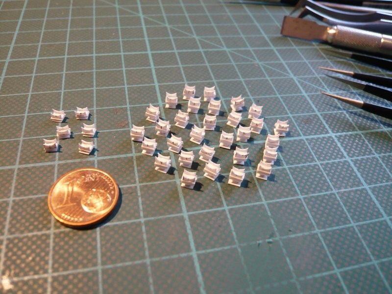 Support No. 1 (red) supports the 16'' rejuvenation (Ø 2,5 mm) immediately in front of the LOX-TSM and is constructed a bit easier.  Source: NASA And No. 6 (red) is this longer support below the 9'' Pipe (Ø 1,4 mm) which is running into the SSME chamber.  Source: NASA Here I have the ring line tentatively layed on the 18 supports, whereby Nos. 1 and 6 (red) are missing.  But that is not enough, because for the holders of the arcuate outlets of both ring lines into the SRB-shafts are needed in each case 12 of these supports (in the sketch blue) which are standing on the Blast Shields. 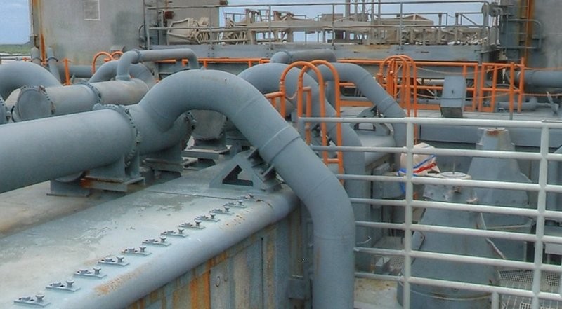 Source: NASA They have a slightly different substructure, but in any case I need 24 of these tiny sickle-shaped supports, I'm looking forward already.  And here I also have arranged the six pretty Rainbirds to complete the picture. 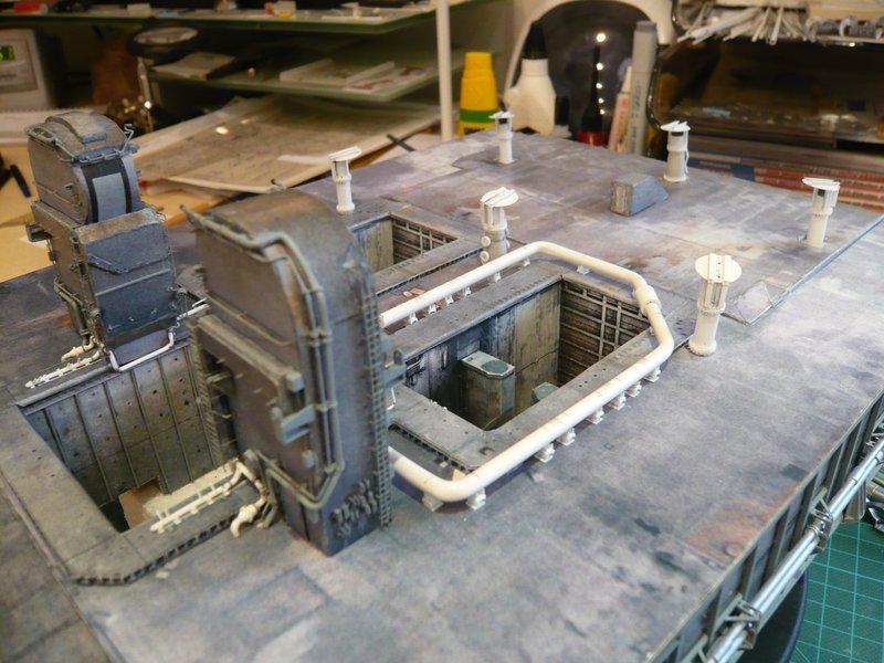 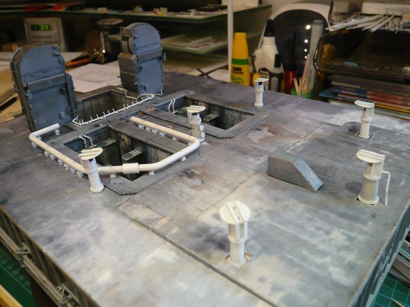 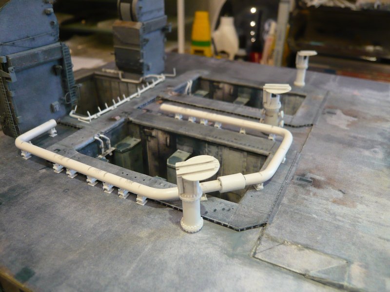 And so now follow the four rear 18'' outlets (Ø 3 mm), for which I have drawn this sketch. 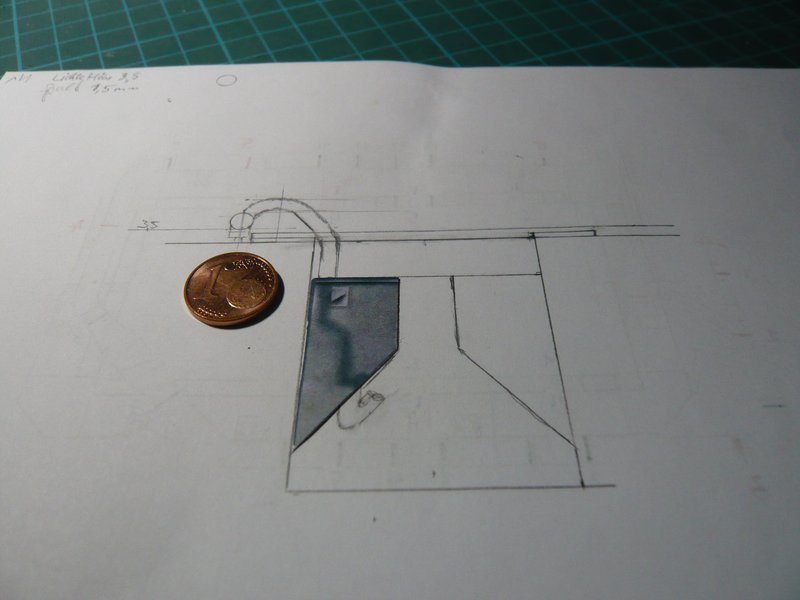 These are admittedly not tapered, but fivefold bent, and are ending below the SRB Supports. 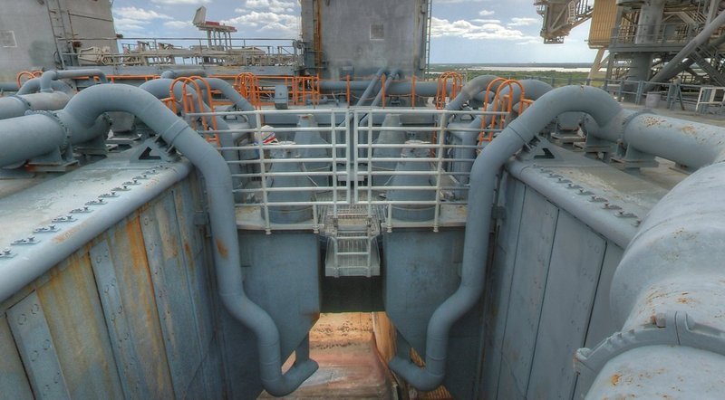 Source: NASA And because I need four of these tortuous "earthworms", for this purpose a balsa template will be worthwhile again.
__________________
Greetings from Germany Manfred Under construction: Launch Pad 39A with Challenger STS-6 (1:144)
|
|
#1049
05-24-2016, 07:07 AM
|
||||
|
||||
|
Challenger STS-6
Manfred,
wow......after all you have accomplished on your build you never cease to amaze me with your modeling talents! Truly fantastic modeling! Bill 
__________________
----------------------------------------------- Seems to have been Deliberately Buried ----------------------------------------------- Where did Gunter Wendt ? 
|
 |
|
|


 Linear Mode

