


|
|
|
#1101
 07-15-2016, 04:51 AM
|
||||
|
||||
|
Thanks elliot!
 Hello everyone, today I want to come back to the 18'' outlets, which indeed still have no outlet openings. And also lacking even the little supports with which they are attached to the SRB supports.  That are these small metal sheets here, 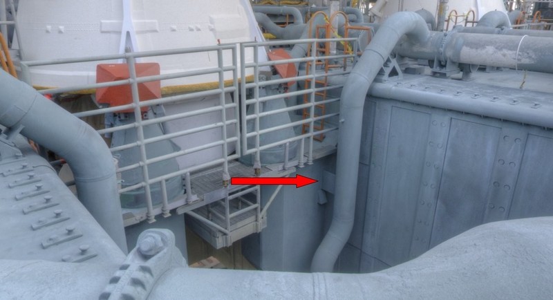 Source: NASA and then these here below the SRB supports immediately above the outlet openings. 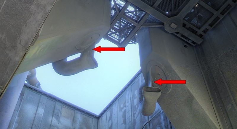 Source: NASA While the supports in the first image are simple square Styrene plates (2.5 mm x 2.5 mm x 0.3 mm), the lower supports have a trapezoidal shape because they sit on the slant of the SRB supports and on the flattened outlet openings. And this results in two little problems, one being the difficulty of determining their dimensions, and closely connected their mounting on the outlet openings below the support slants.  For the dimensions this image was relatively well suited. It can be seen that the outlet opening and the trapezoidal sheet ranges up to about the middle of the SRB support. 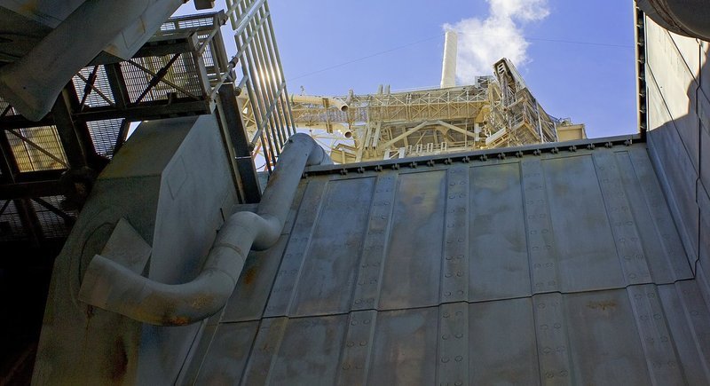 Source: NASA Accordingly the size of the support is about 3.7 / 2.5 mm x 3.7 mm x 0.3 mm. For the adaptation and assembly of these supports at the outlets, I have modified my previous mounting template for the tapered 18''/12'' outlets to the following Balsa jig which has the shape of the SRB supports.  The support is made of 8 mm Balsa and thus corresponds to the thickness of the SRB support. In the base plate beneath sits the 24'' ring line for an exact alignment of the 18'' outlet. As spacers I have used 2.5 mm H-beams (Evergreen). 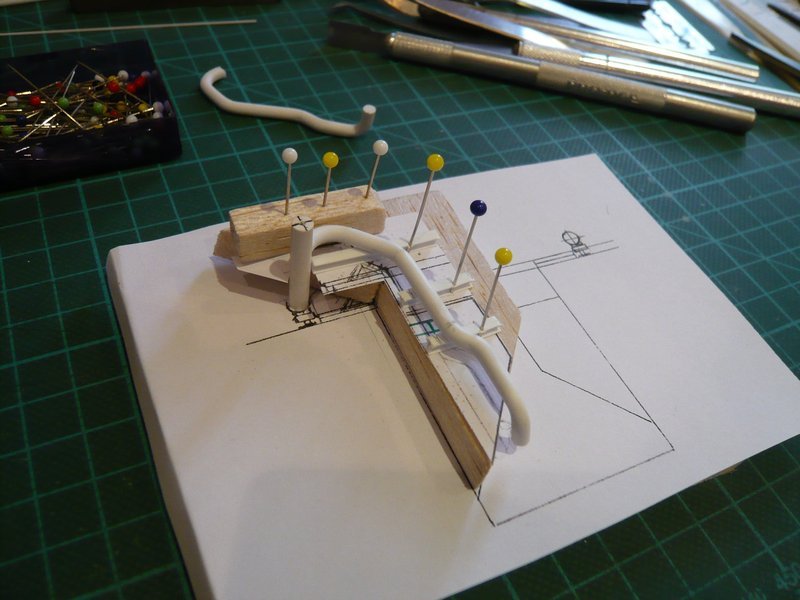 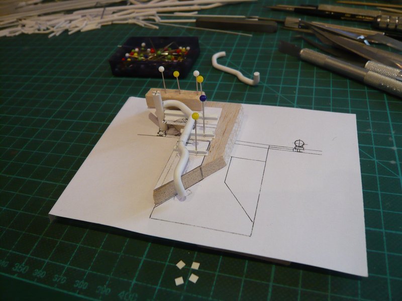 Now I have fixed the location of the outlet from both sides and from above, so that it can no longer slip. 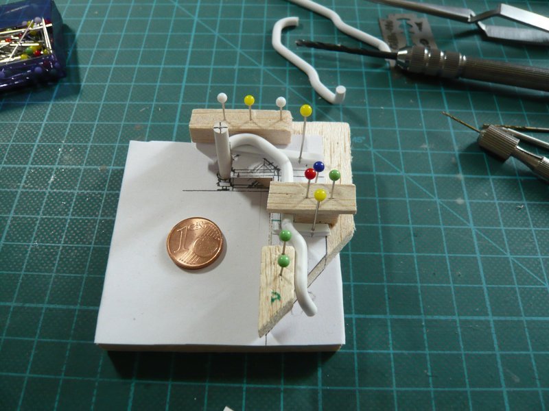 And in the gap between the support and the outlet end can now be adapted the trapezoidal support plate and also glued later. 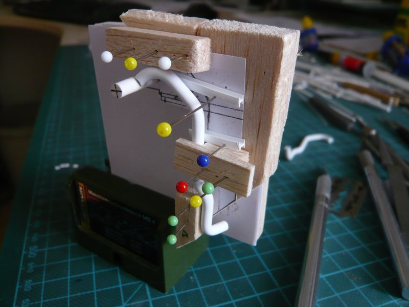 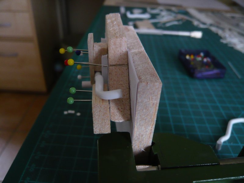 But previously the outlet opening must be hollowed and flattened out.  
__________________
Greetings from Germany Manfred Under construction: Launch Pad 39A with Challenger STS-6 (1:144) Last edited by spacerunner; 07-15-2016 at 05:06 AM. 
|
|
#1102
07-15-2016, 05:51 AM
|
||||
|
||||
|
Therefore at first I have tried to pre-drill the outlet end as centrally as possible with smaller diameters (up to 2.4 mm), but this is not simple and is slightly shifted again.
   After the final drilling with Ø 2.8 mm, the wall is rather thin and unfortunately unequally thick, 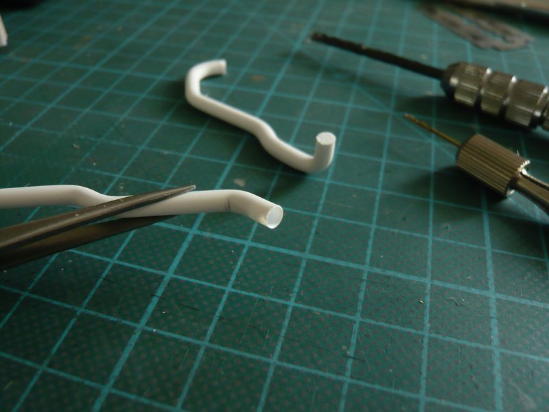 which is unfavorable for the subsequent warm-flattening of the opening (on the left). 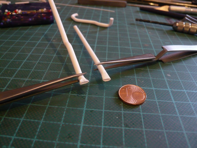 Another possibility (right) would be to use a drilled Styrene pipe (3.2 mm), of which the wall would be indeed more uniformly, but slightly thicker, which would be acceptable.  The form itself certainly looks cleaner. The form itself certainly looks cleaner. 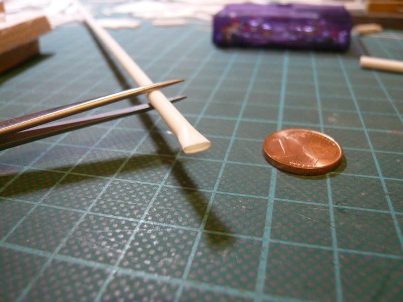 Of which now however still had to be cut off a short end piece and to be glued at the shortened outlet end, as well as additionally refinished, which would be an additional fiddling again.  Meanwhile, I've bought a drill with Ø 2.5 mm which hopefully is better suited, let's see ... Finally, I have marked nor the positions of the upper support metal sheets. 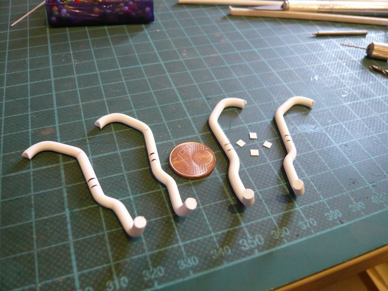 Well then until soon. 
__________________
Greetings from Germany Manfred Under construction: Launch Pad 39A with Challenger STS-6 (1:144)
|
|
#1103
07-16-2016, 01:40 AM
|
||||
|
||||
|
Hello everybody,
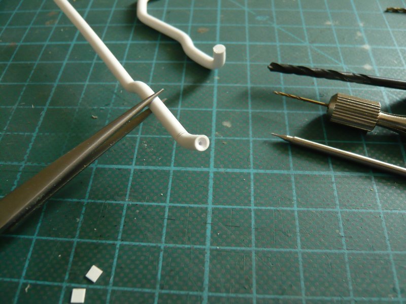
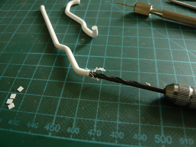
now missing only the outlet openings that I wanted to try again. The difficulty is, as I said, the central drilling, which you cannot do it immediately with the final diameter, which is why this time I drilled a dummy (3.2 mm) in smaller gradations. After center punching as central as possible  I started with Ø 1,3 mm, specifically about 6 mm deep, that means gradually in and out, so there is no chip congestion. I started with Ø 1,3 mm, specifically about 6 mm deep, that means gradually in and out, so there is no chip congestion. 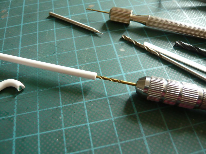 And that looks already pretty centrical.  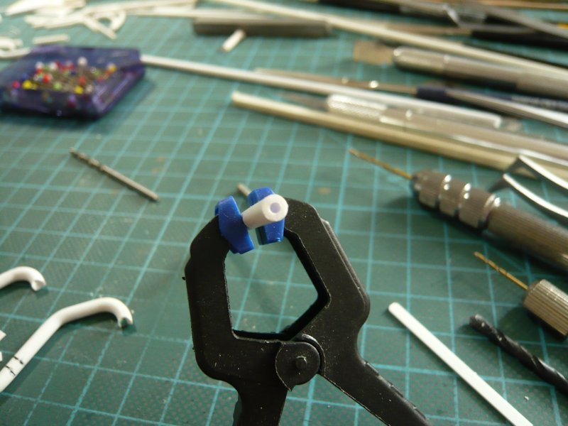 Thereafter followed Ø 2,0 mm, 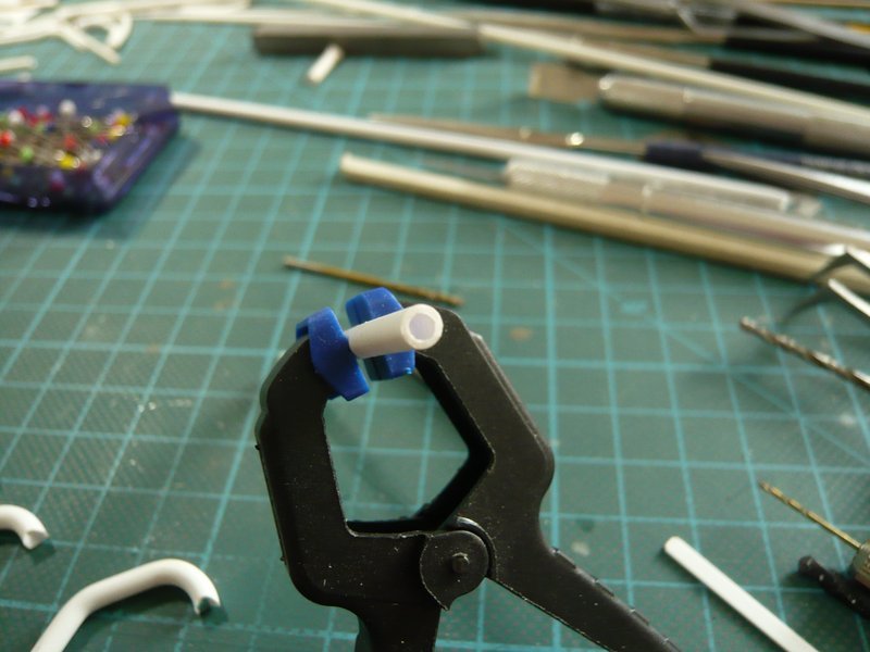 Ø 2,3 mm, 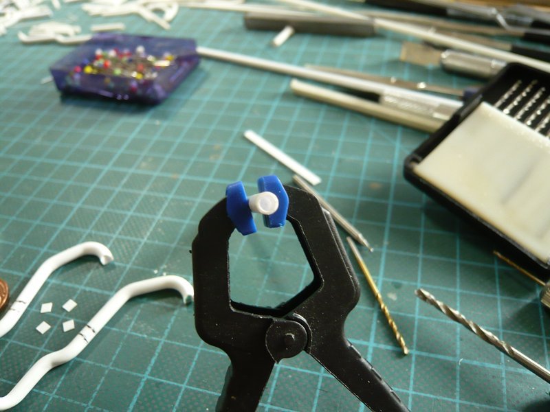 Ø 2,5 mm, 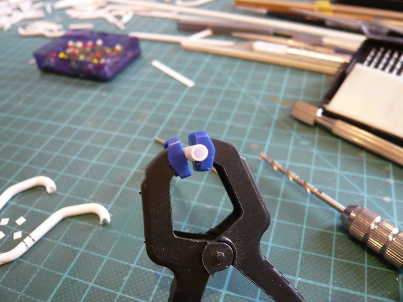 and finally still a slight countersinking with Ø 2.7 mm for reduction the visible wall thickness, just because of the optics. 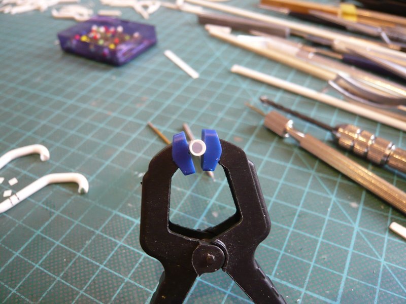 And then I've briefly heated carefully and gradually slowly flattened the front end (3 mm) with a core (0.75 mm x 2.5 mm) down to 1.7 mm height, but not this way ...  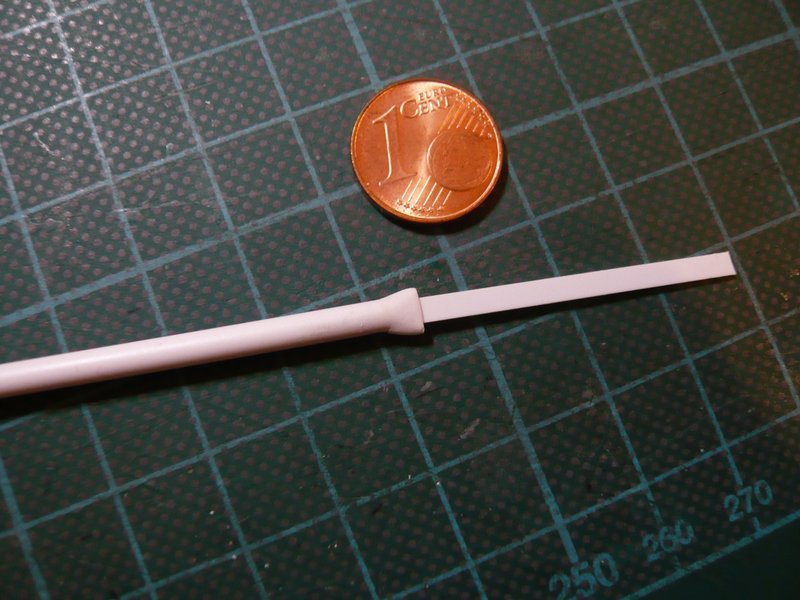 And that can be quite impressive, right?  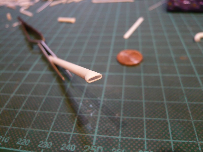 And therefore I can probably now also venture to the final outlets, hopefully it'll work also as well then.
__________________
Greetings from Germany Manfred Under construction: Launch Pad 39A with Challenger STS-6 (1:144) Last edited by spacerunner; 09-19-2016 at 03:28 PM.
|
|
#1104
07-16-2016, 07:30 AM
|
||||
|
||||
|
Hello everyone,
I have made a final test on a real component and thereto used my first 18'' outlet prototype, which still was lying around and anyway is good for nothing. He still had Ø 3,0 mm and was due to the bendings no longer circular at the end , but came just right as a dummy. Its end I have drilled out to Ø 2,5 mm, 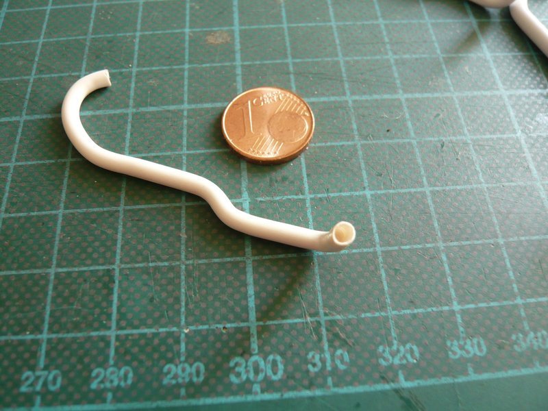 and then flattened, as usual. 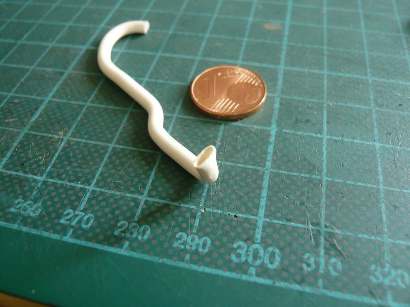 As can be seen, one can scratch the outlet opening also directly at the bent outlet. 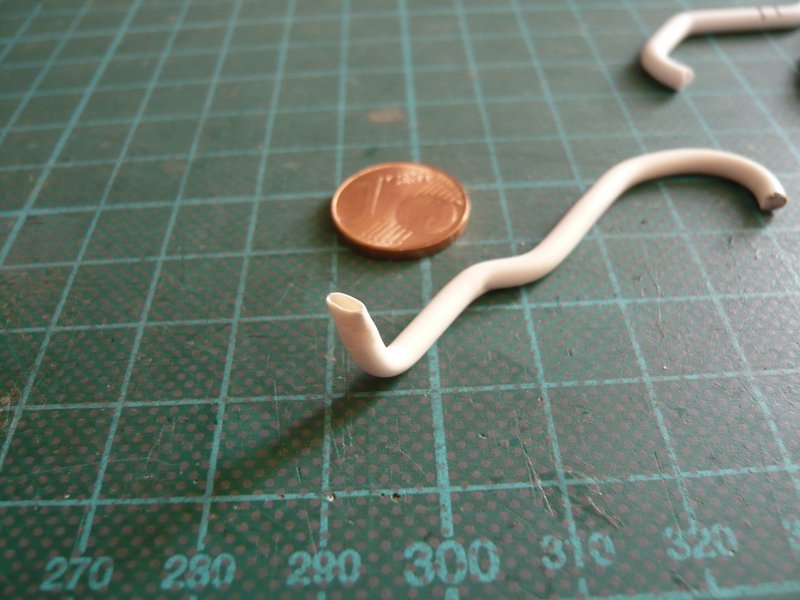 And therefore I can now also get down to business with the four final outlets (Ø 3,2 mm).
__________________
Greetings from Germany Manfred Under construction: Launch Pad 39A with Challenger STS-6 (1:144)
|
|
#1105
07-16-2016, 02:09 PM
|
|||
|
|||
|
Real progress Manfred! Feels good doesn't it?
__________________
This is a great hobby for the retiree - interesting, time-consuming, rewarding - and about as inexpensive a hobby as you can find. Shamelessly stolen from a post by rockpaperscissor 
|
|
#1106
07-16-2016, 04:59 PM
|
||||
|
||||
|
Thanks elliot,
as already said, this SSWS is a fairly complex system and difficult to scratch in detail, especially since I have to determine the dimensions of all parts laboriously from images, which is very time consuming and grueling.  Until now, almost everything was successful, but there is still enough to do. But I am hopeful that it will ultimately be accomplished.
__________________
Greetings from Germany Manfred Under construction: Launch Pad 39A with Challenger STS-6 (1:144)
|
|
#1108
07-17-2016, 01:22 AM
|
||||
|
||||
|
Thanks Ken for your nice comment,
yep, this is first of all a question of will, and then one needs also still a lot of patience ... And having fun in doing is eventually also still important.
__________________
Greetings from Germany Manfred Under construction: Launch Pad 39A with Challenger STS-6 (1:144) Last edited by spacerunner; 09-19-2016 at 03:27 PM.
|
|
#1109
07-19-2016, 09:50 AM
|
||||
|
||||
|
Hello everybody,
and this I have implemented now, in hopes that it will fit somehow. First, I have drilled out the final four 18'' outlets, as already described. 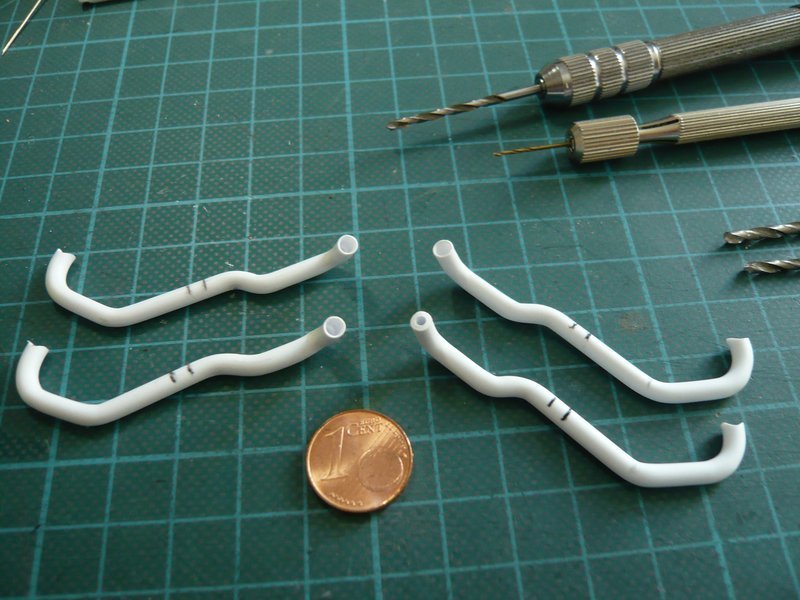 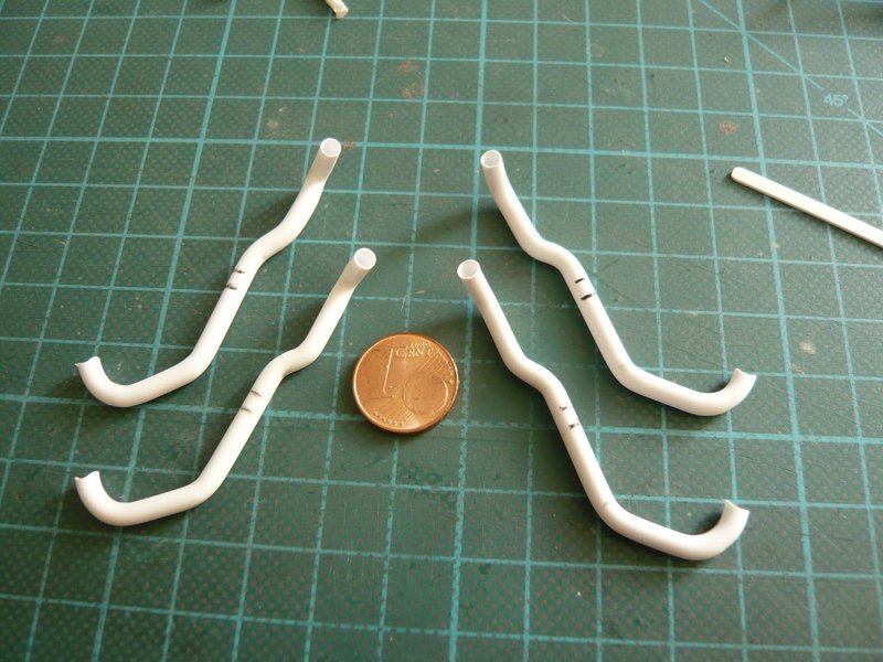 So far so good, and now came the cautious forming of the outlet openings with the help of the Proxxon Gun, for what I have inserted a core. 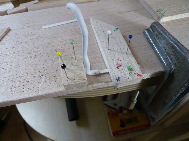 Nevertheless, one must be extremely careful during heating, so that the thin-walled opening is not shrinking suddenly.  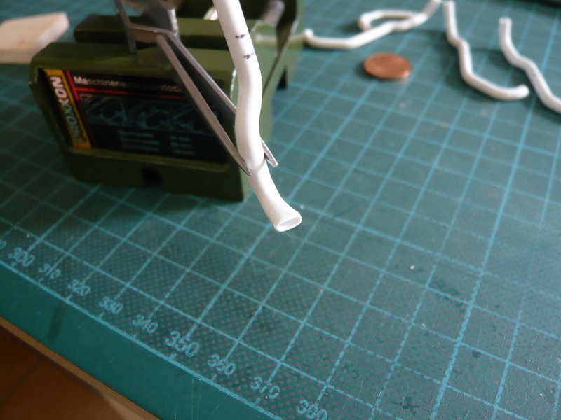 And how the subsequent fitting shows, the position of the opening under the balsa support looks quite passable. 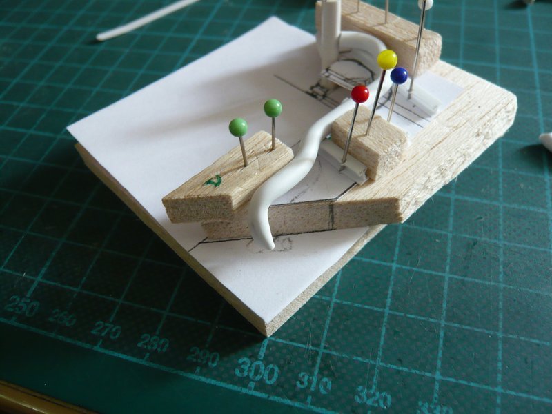 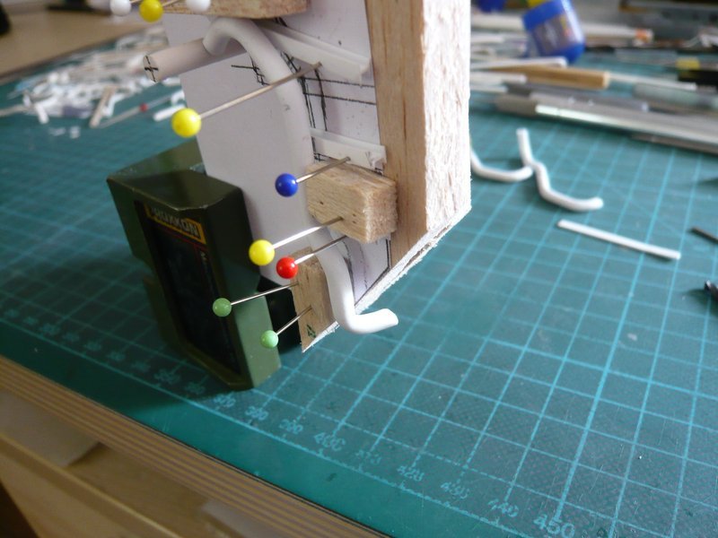 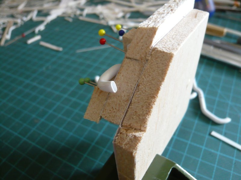 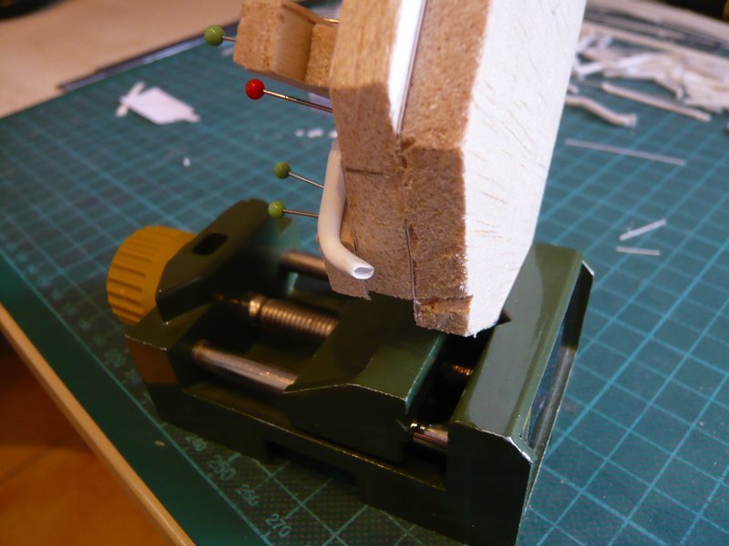 And now to the lower support plates, which can be seen in this panorama of the STS-134 on the MLP 2. 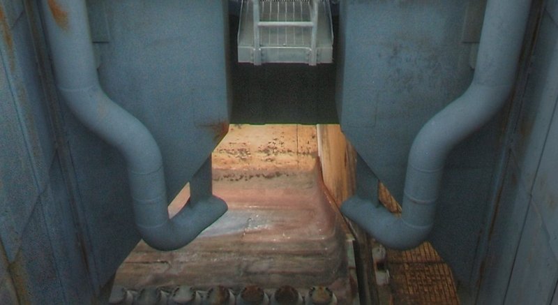 Source: NASA First, I have tested my estimated size with a paper dummy, which was still a bit too small. 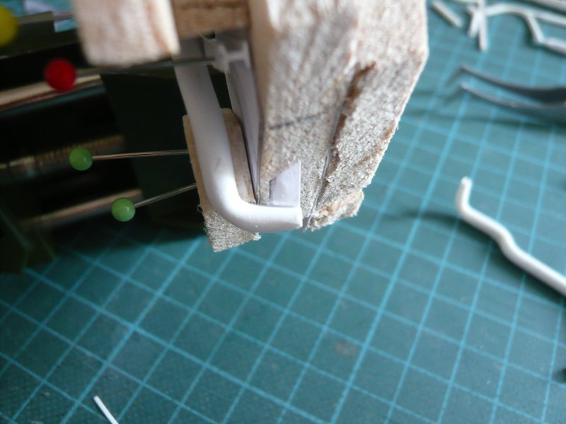 With the adjusted support plate of 0.3 mm Stytene it looks much better already.  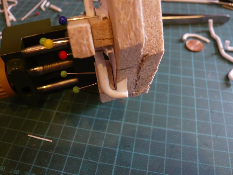 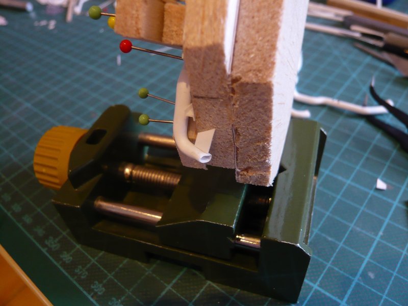 So both plates can be glued now on the outlets in place.
__________________
Greetings from Germany Manfred Under construction: Launch Pad 39A with Challenger STS-6 (1:144)
|
|
#1110
07-19-2016, 10:16 AM
|
|||
|
|||
|
Looks like substantial progress here! All your hard work is beginning to pay dividends Manfred. Excellent job!
__________________
This is a great hobby for the retiree - interesting, time-consuming, rewarding - and about as inexpensive a hobby as you can find. Shamelessly stolen from a post by rockpaperscissor
|
 |
|
|


 Linear Mode

