


|
|
|
#1571
 02-05-2018, 07:28 PM
|
||||
|
||||
|
Fantastic!


|
|
#1572
02-06-2018, 07:17 AM
|
||||
|
||||
|
Thanks Becky,
I am pleasantly surprised myself by the quality of the AFTCs, which shows that Shapeways is on a good way.  And also after two days, the state of the Bare-Metal Foil stripes is unchanged stable, 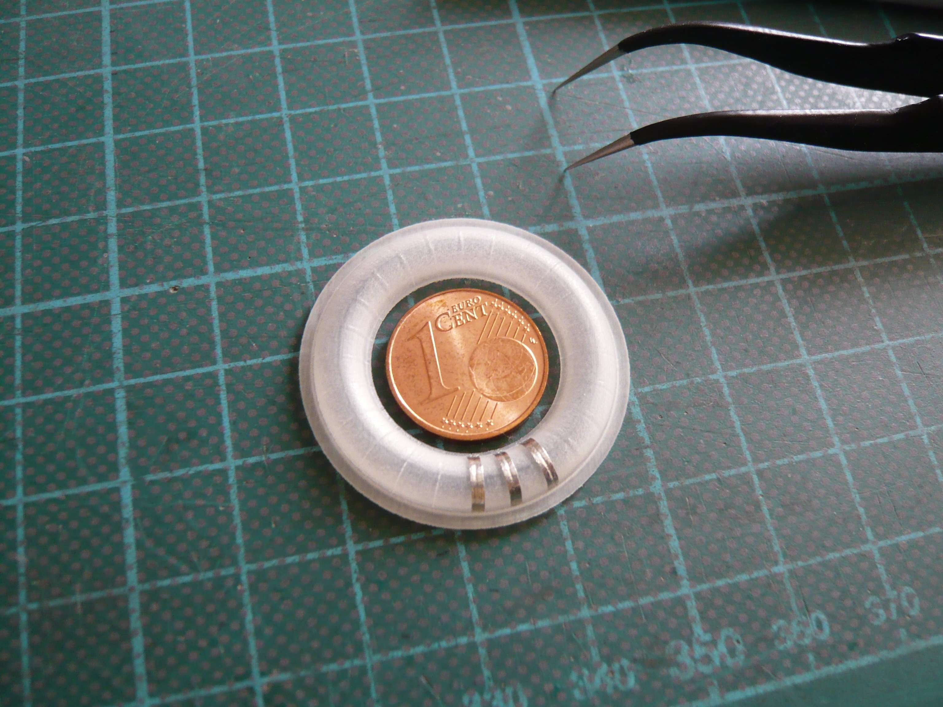 and looks very well.  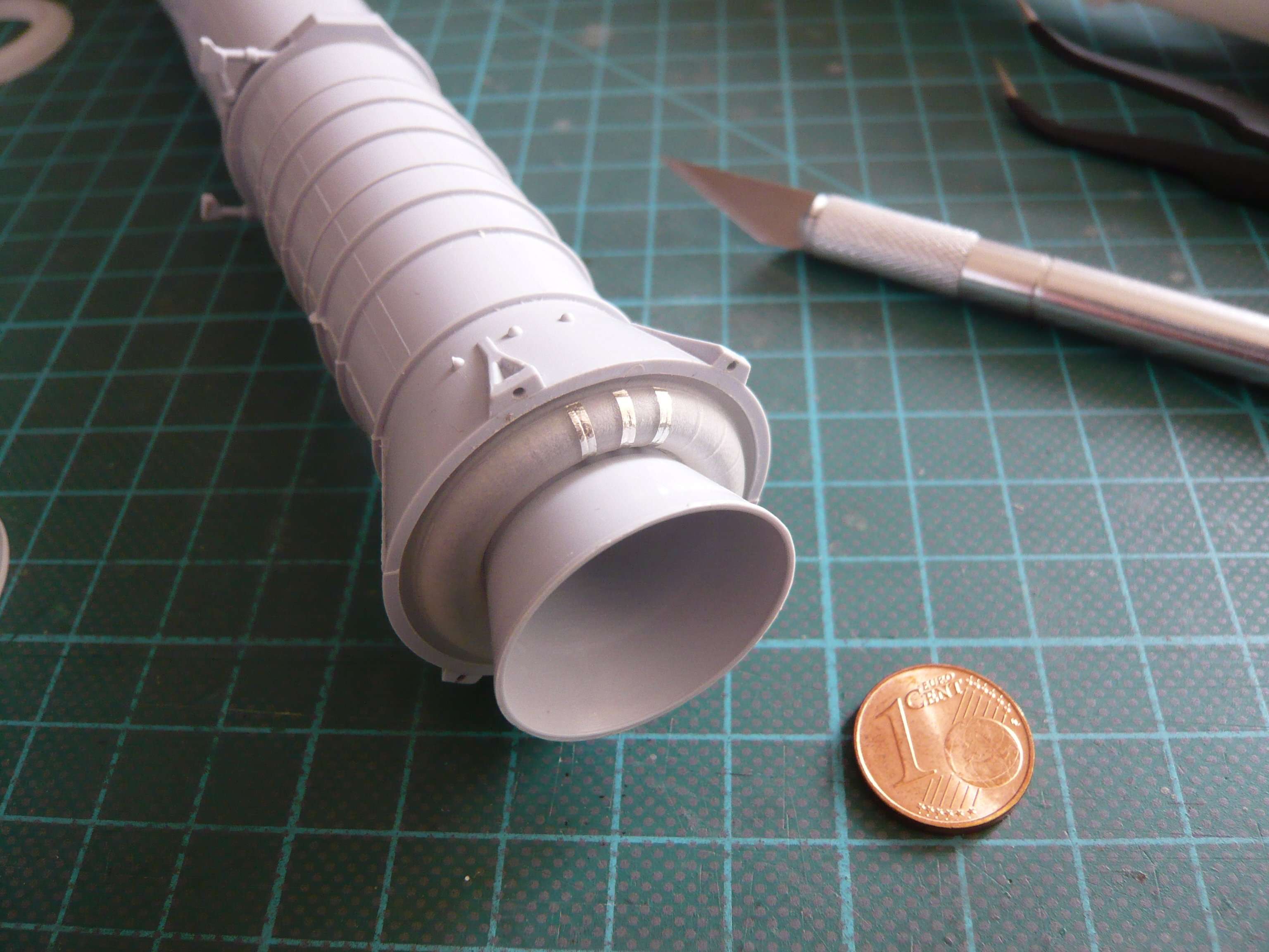 
__________________
Greetings from Germany Manfred Under construction: Launch Pad 39A with Challenger STS-6 (1:144)
|
|
#1573
02-06-2018, 11:16 AM
|
||||
|
||||
|
I believe you have a winner here, Manfred.
__________________
Non Sufficit Orbis-The world is not enough.
|
|
#1575
02-07-2018, 10:43 AM
|
||||
|
||||
|
Thanks guys for your nice feedback.
 I also think that the ASTCs with the Bare-Metal foil strips will look awesome. One can really fall in love with these 3D parts.
__________________
Greetings from Germany Manfred Under construction: Launch Pad 39A with Challenger STS-6 (1:144)
|
|
#1576
02-08-2018, 05:21 PM
|
||||
|
||||
|
Hello everybody,
after having been more intensively involved with the AFTC rings that have been printed meanwhile by Shapeways and tested by me, I want to go back to the 3D modeling of the Intertank wherewith Michael Key had started last December, what I've been posting about.  Therefor I had sent him in the result of my research my drawing and the estimated Stringer dimensions without and with foam insulation, where actually only the dimensions with foam insulation for his 3D modeling are relevant.  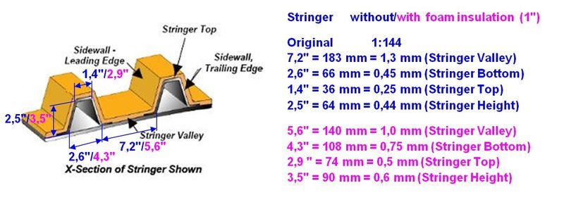 Thereupon he had to adjust his 3D model once again, which I as a 3D rookie have not imaginated so complicated, but which should turn out to be a fallacy.  At the beginning of the year he told me that he has meanwhile modeled another version with these stringer dimensions, given by me, 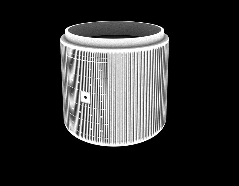 Source: shapeways.com/forum (Michael Key) consisting of each 26 Stringers in the two Thrust Panels and of each 40 Stringers in the intervening Stringer Panels. But somehow I immediately stumbled over his number of 40, that's totally 80 stringers in the Stringer panels, which I was very surprised because I dimly remembered a number 108 in our German Raumcon discussions, wherewith the confusion around numbers and terms started at the beginning of my project start (11/2011).  After intensive researches I finally found the explanation in the System Definition Handbook SLWT, in which the Intertank structure is described quite well. 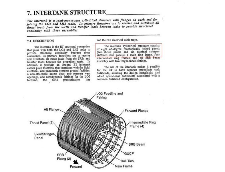 Source: Space Shuttle/External Tank System Definition Handbook SLWT 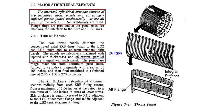 After that one has to distinguish the following terms:  While in the six Skin/Stringer Panels (45°) there are each 18 of these Stringers, 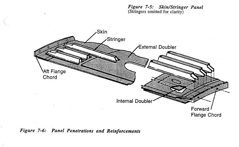 one speaks in the two Thrust Panels of Ribs, whereby in each case 26 parallel ribs as well as seven circumferential ribs are integrated in these panels, 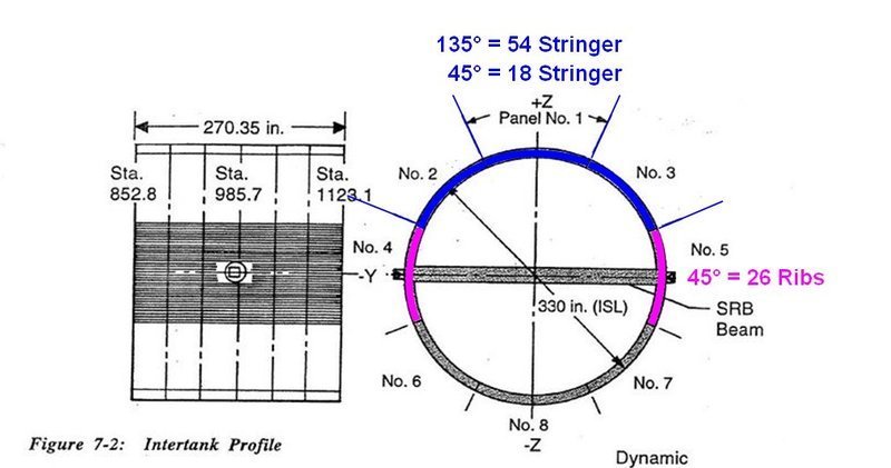 Therewith was clarified at least the number of stringers, namely 108, which showed that Michael Key's 3D model had with totally only 80 too little stringers. And now I had to explaine this fact heavy-heartedly Michael Key, whereby I was afraid that he would lynch me for it.  Thereupon he was very disappointed and had initially thrown in the towel quite frustrated. But of course, I did not want to give up that fast ...  On the other hand, it would probably have been more useful to distribute the Stringer number onto the circumference of the eight 45° panels, whose drawing he had also been given by me. But in hindsight one is always smarter than before ... In the meantime, I did it my way both for the six Stringer Panels and for the two Thrust Panels with following results and sent it to him, in the hope that he would have an insight as well as a good will.  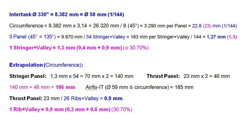 Long story short, therewith I obviously had affected his honor, so that he was ready to go on. But I had to confirm to him that it would finally remain, in each case 54 stringers in the Stringer panels (135°) and in each case 26 ribs in the two Thrust panels (45°), whereupon I gave him my word and was jolly glad.
__________________
Greetings from Germany Manfred Under construction: Launch Pad 39A with Challenger STS-6 (1:144)
|
|
#1577
02-10-2018, 06:46 PM
|
||||
|
||||
|
Hello everybody,
there are progresses to be reported of Michael Key's intertank modeling. After the number of Stringers (108) and that of the Ribs (52) have been clarified, we now have to clarify some further details on the Intertank, which are marked in this image, some of which have already been integrated into Michael's model.  Source: NASA Here are his latest 3D pictures, whereby I wondered at first about these six plates in the Access Door,  that I've never seen before. that I've never seen before. Furthermore, I noticed that the size and location of the Access Door (AD) and the Carrier Plate (CP) cannot be quite right, 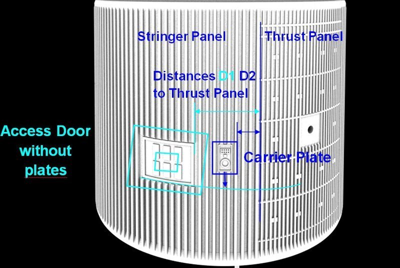 Source: shapeways.com/forum (Michael Key) which is why I determined them more precisely based on photos, wherefore I used the agreed reference size 1 Stringer+Valley = 1,3 mm. At first I used this great direct view of the Carrier Plate, which has almost no perspective distortions, what should be considered. For the determination and conversion of the measures, the following explanation of my numbers in the photos with and without mm is necessary, so that one does not get confused. Numbers without mm are measured values in the respective photo, and Numbers with mm are the converted measurements in 1/144. And if one compares this photo with his model, stands out that the distance D2 of the Carrier Plate from the Thrust Panel is too large because it should be only 2 Stringer+Valley (2,6 mm).  Source: NASA With this distance and the determined dimensions of the Carrier Plate of 3.5 mm x 5.0 mm (W x H) I am afterwards in this photo of the Access Door boarded, which unfortunately is not so distortion-free in the area of the door. And in this photo one can see that the door is flat and has no attached panels. 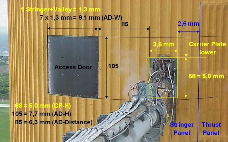 Source: NASA Here's a similar picture at which the access door panel is removed, which is attached with 44 flat profile screws.  Source: NASA Thus, the Access Door and the Carrier Plate would have the following dimensions: Access Door: 9,1 mm x 7,7 mm (W x H) Carrier Plate: 3,5 mm x 5,0 mm (W x H) As one can see in the following image, the Fairings of the LO2 Feedline (17'') and of the GH2 Press. Line (2'') were added, as well as the LH2 PAL Ramp and the LO2 PAL Ramp, as well as the Supports for the two Press. Lines and the associated Cable Trays. 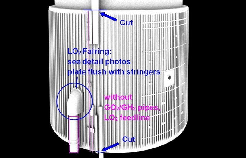 Thereto Michael has suggested to omit the two thin Press. Lines and the Cable Trays, as they would go beyond the intertank anyway and could possibly break off during printing or transport. He was worried about the PAL Ramps. While the LO2 PAL Ramp could survive at the top, he fears that the LH2 PAL Ramp could probably break because it's very long and thin. So he asked if he should cut them off at the ends of the Intertank, which I agree with. 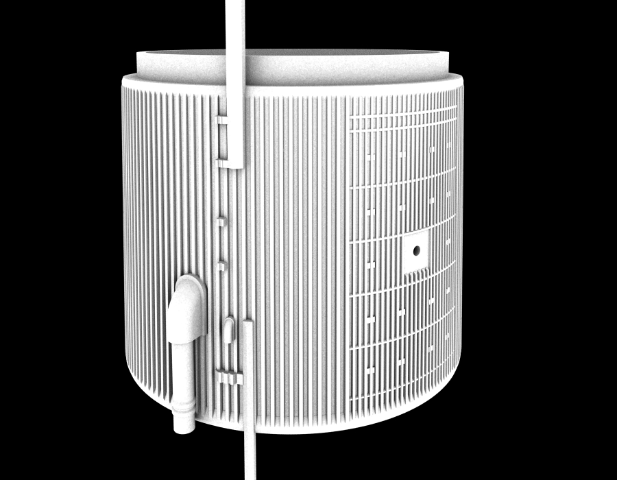 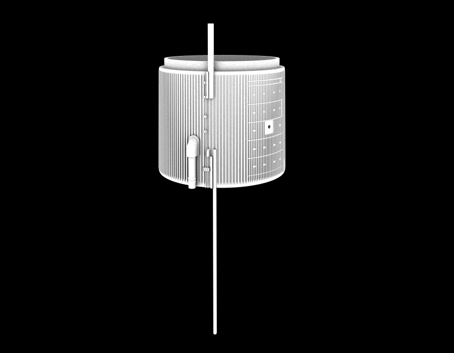 Since I anyway want to insert the LO2 Feedline and the Press, he should omit them away, but not the Cable Trays, because I could continue them to the front and backwards. Then I still showed him these two photos, on which one can see that the bottom plates of the Fairings are flush with the stringers and not put onto, what he has accepted and wants to change. 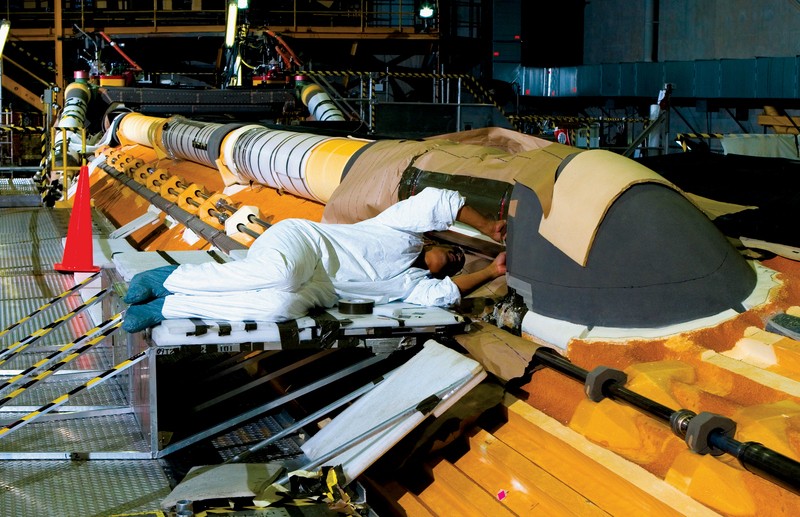 Source: NASA 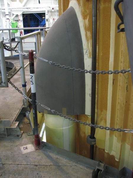 Source: NASA These were essentially my hints and correction wishes.  Regarding of his plates attached on the Access Door, which I had queried, he sent me this photo here, which surprised me, since I did not have seen it yet. 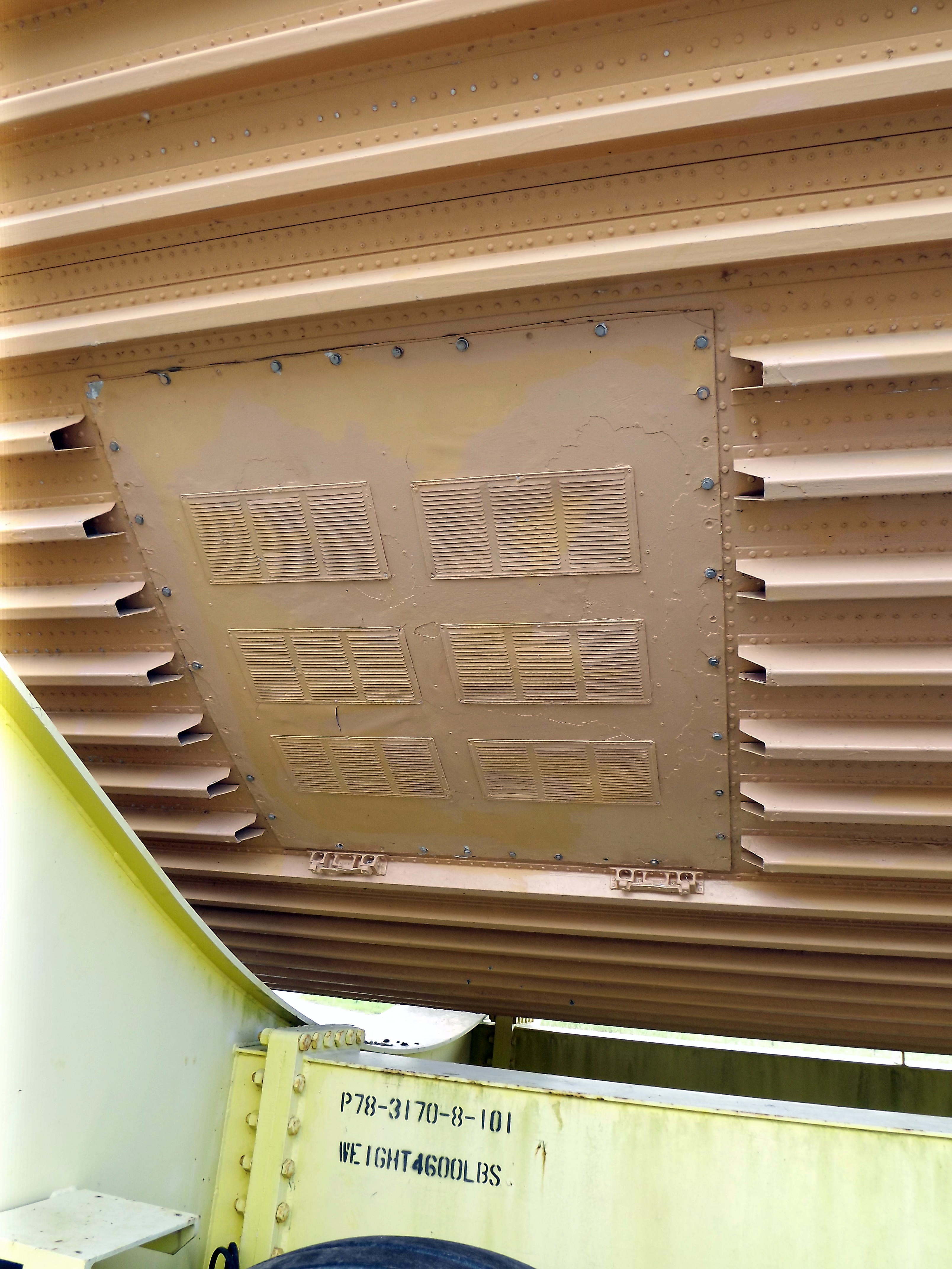 That's why I asked him if he had any source, whereby it could possibly be a Mock-up.  I believe that shows once again that a timely and consensual coordination of such details is important for a smooth process, that's why one never stops learning.
__________________
Greetings from Germany Manfred Under construction: Launch Pad 39A with Challenger STS-6 (1:144) Last edited by spacerunner; 02-10-2018 at 07:02 PM.
|
|
#1579
02-11-2018, 01:57 AM
|
||||
|
||||
|
Thank you for your kind words and your sympathy and condolences.
Stay tuned my friend.
__________________
Greetings from Germany Manfred Under construction: Launch Pad 39A with Challenger STS-6 (1:144)
|
|
#1580
02-11-2018, 12:39 PM
|
||||
|
||||
|
Hello everybody,
let's go step by step on our way to the goal, here are the next images of Michael Key's 3D modeling. As one can see in this image, he has omitted both the six plates in the door and adjusted their size, as well as he had corrected the distances of the AD and the CP from each other and from the Thrust Panel. 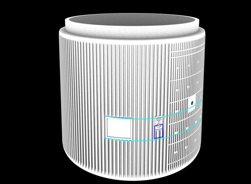 Source: shapeways.com/forum (Michael Key) The position of the CP, however, remained unchanged and still sits too high up, although I had already marked it in this last image, Source: NASA what one can also see in this photo. 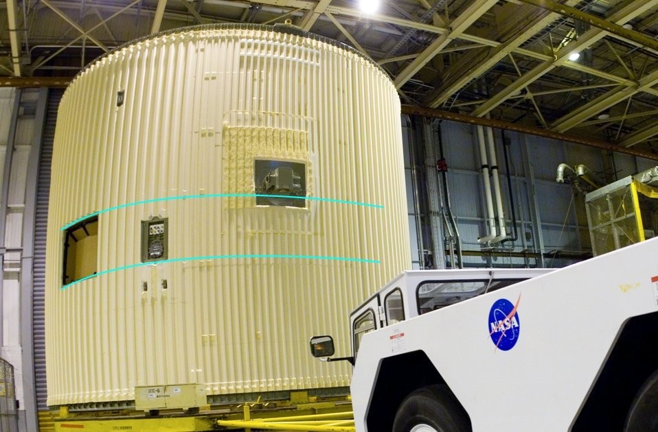 Source: forum.nasaspaceflight.com (Jester) Furthermore, it is noticeable that the bottom plate of the large LO[sub]2[/sub] Fairing admittedly is flush with the stringers, but not that of the small LH[sub]2[/sub] Fairing, 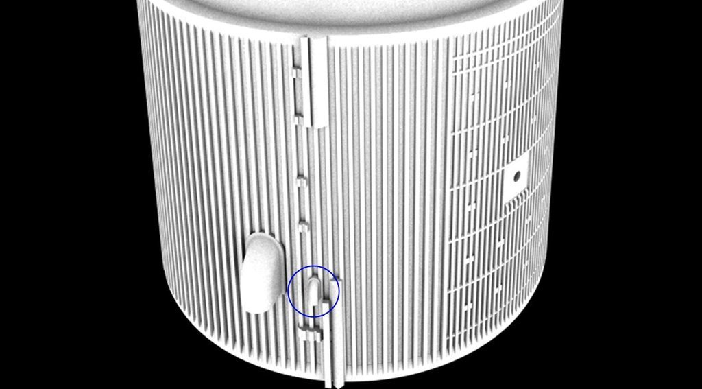 Source: shapeways.com/forum (Michael Key) which is still to be corrected, according to the following photo, but hopefully will not cause any problems.  Source: NASA Then here are two more images of the small supports of the GH[sub]2[/sub]/GO[sub]2[/sub] Press. Lines (2''), first with the indicated lines, 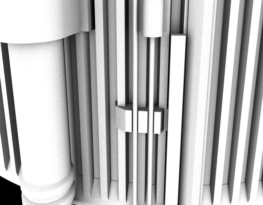 Source: shapeways.com/forum (Michael Key) and here the final design without the lines, whereby the thin wires (Ø 0.3 mm) will separately be inserted later and covered with small caps. 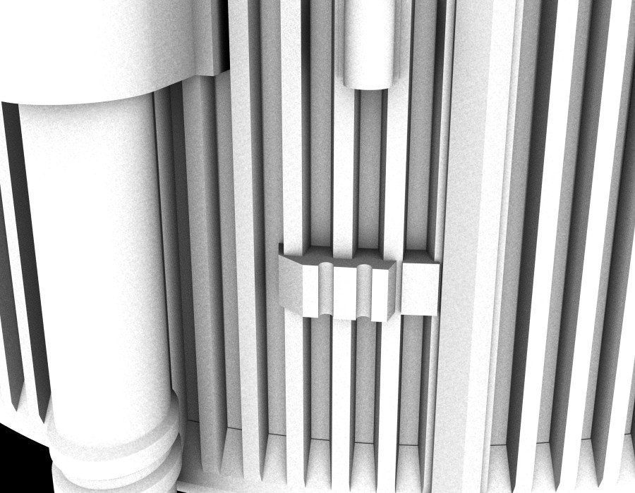 Source: shapeways.com/forum (Michael Key) Now I hope that these last changes can also be considered by him, according to which an upload of the 3D model to Shapeways nothing would stand in the way.  But Michael Key wanted to be honest and told me, that there are some very small parts in this model that could possibly overstrain Shapeways' possibilities, so the model might not pass their inspections the first time around. That would be normal, and Shapeways would let him know the problem, which he would correct.  That's why I'm very curious, but initially his modified model is still due.
__________________
Greetings from Germany Manfred Under construction: Launch Pad 39A with Challenger STS-6 (1:144) Last edited by spacerunner; 02-12-2018 at 02:01 AM.
|
 |
|
|


 Linear Mode

