


|
|
|
#2621
 04-09-2022, 02:34 PM
|
||||
|
||||
|
Hello everybody,
to finally complete the transporter, I've also attached the second set of Windscreen wipers to the Driver's cabin on the back side, for what I also came up with an improved handling. This could perhaps be interesting for one or the other who might want to glue such tiny and thin parts together too.  Especially since grasping of the windscreen wiper with the wiper blade pointing downwards is not that easy with my Tape Adhesive Applicator,  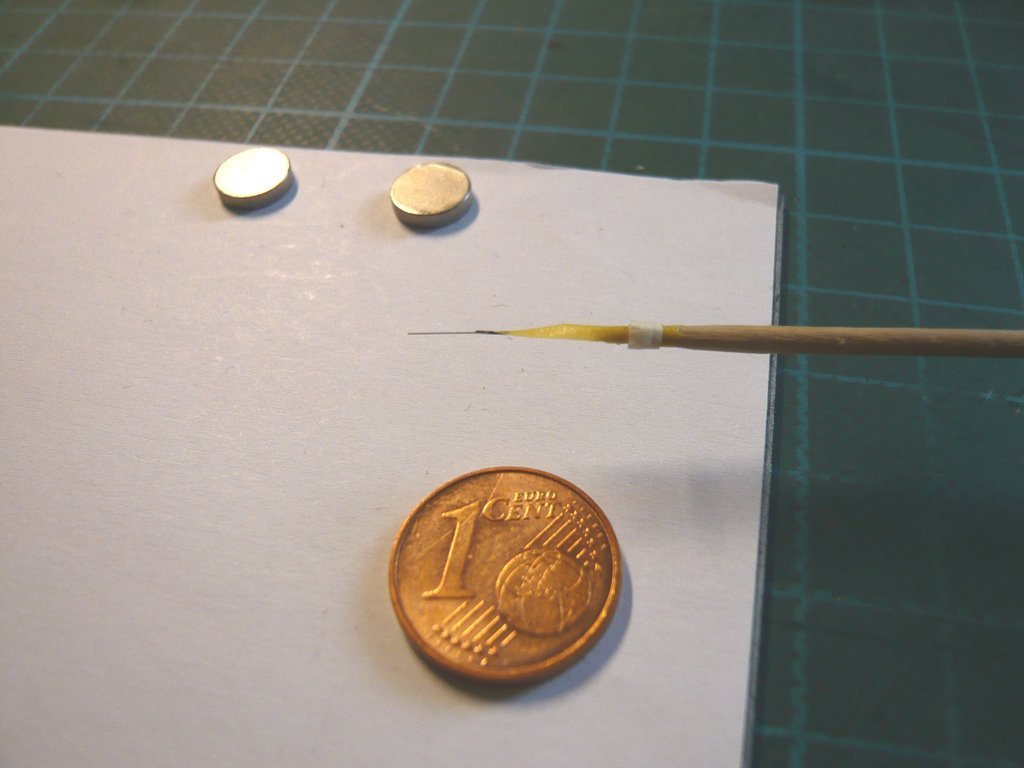 this time, before gluing, I picked up the wiper in this position with a wider pair of tweezers and held the tweezers in a clamp, so that it were ready to hand after dabbing the CA droplet onto the holder.  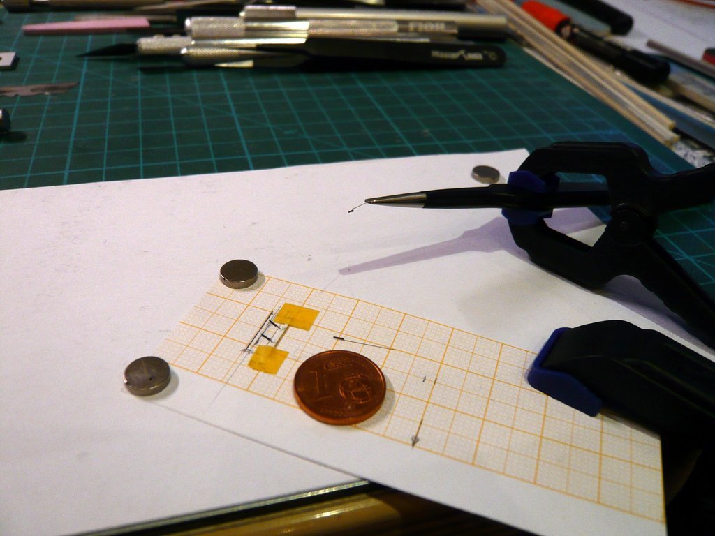 In this position I was able to safely pick up the tweezers with the clamped wiper and to set it down on the glued area with a steady hand, 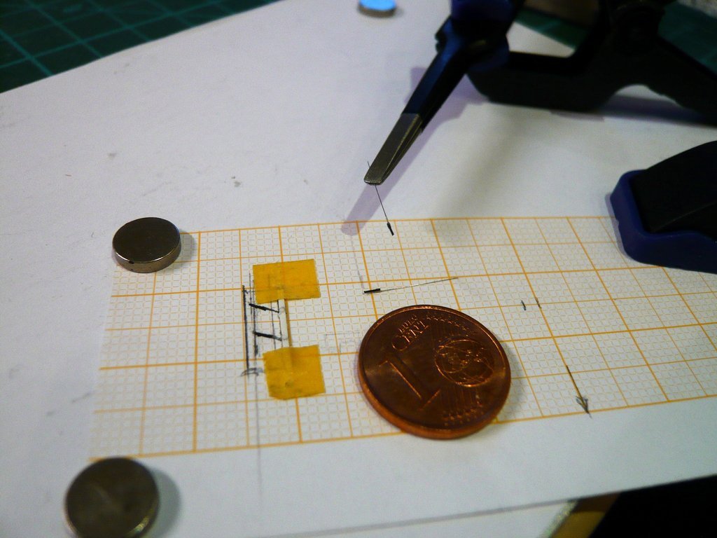 whereby a spacer was placed underneath, which then all worked well together.  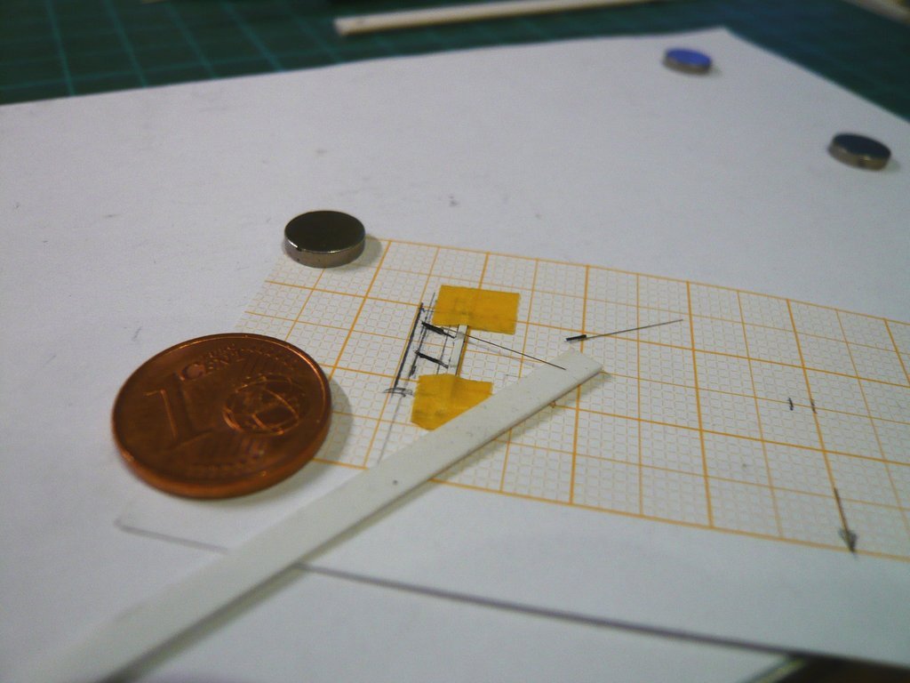 And then it was the turn of the second wiper, 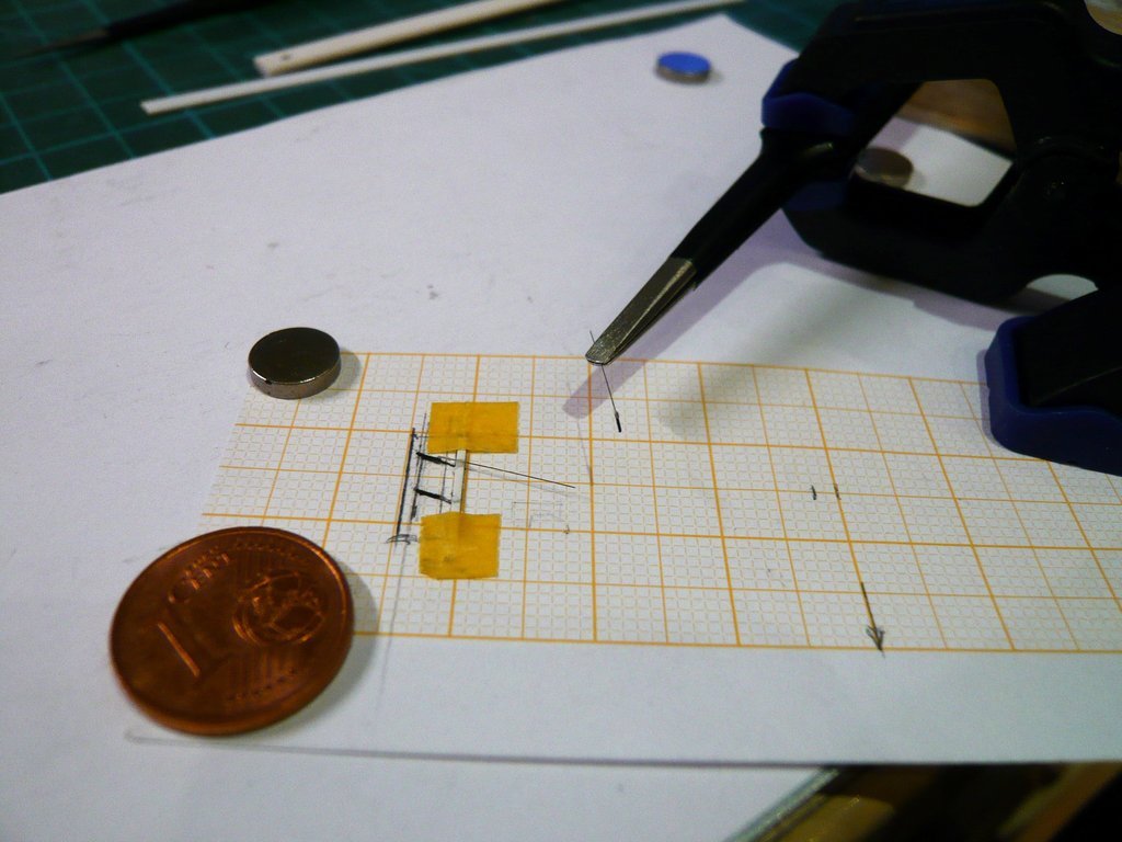 which worked just as well. 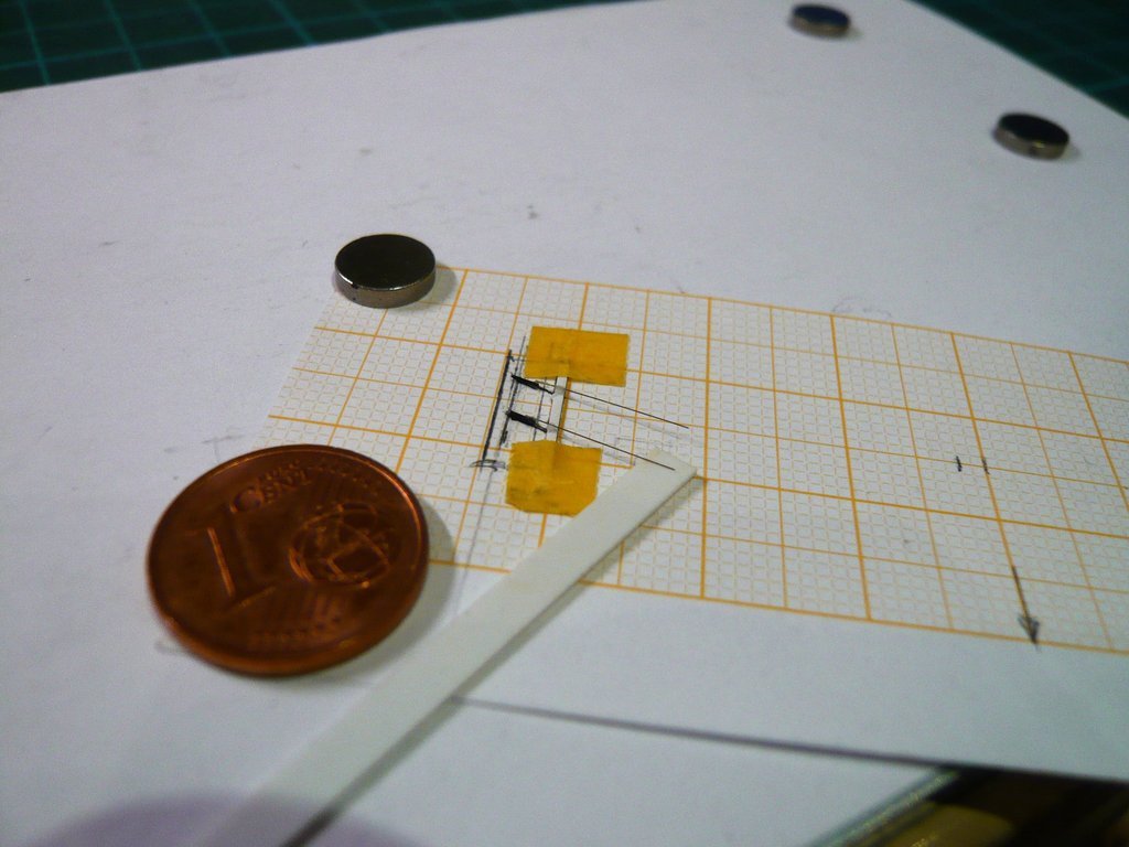 Then the overhangs of the holders were cut off, 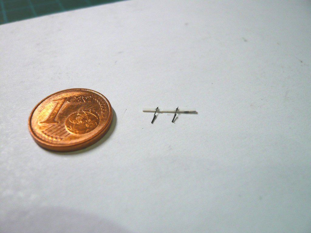 and the holder strip with the pair of wipers was glued onto the driver's cab. 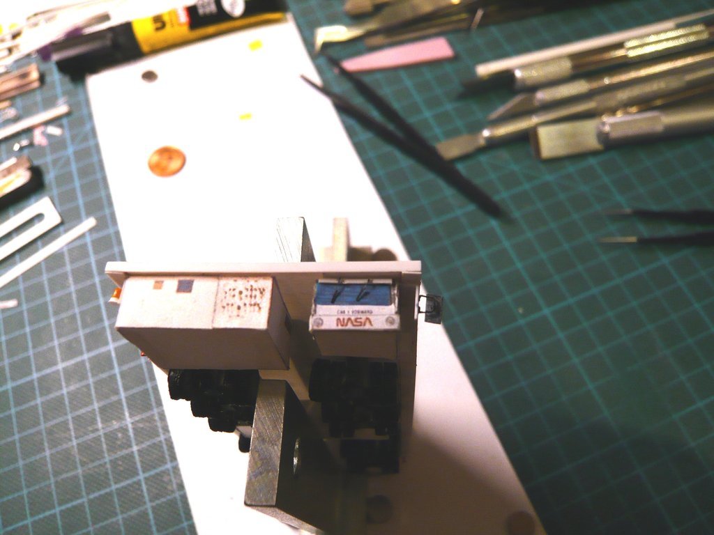 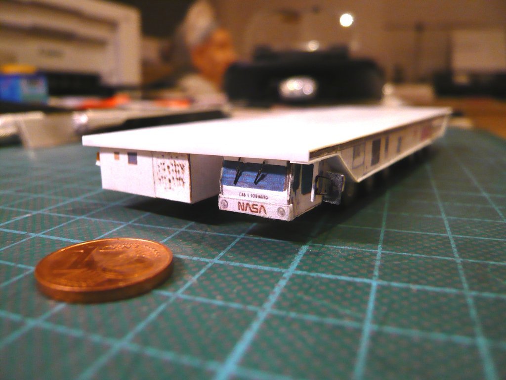 With that the transporter is now complete and ready to go, and so I can move on to the Payload Canister,  Source: retrospaceimages.com (STS-6) which is sure to become a very interesting sub-project too.  
__________________
Greetings from Germany Manfred Under construction: Launch Pad 39A with Challenger STS-6 (1:144) 
|
|
#2622
04-10-2022, 07:52 AM
|
||||
|
||||
|
Hello everybody,
well, imagine that the Transporter drove with the Payload Canister together with the payload inside to the Launch Pad, so that the payload via the RSS Payload Bay can bee loaded into the Payload Changeout Room (PCR). From there it will sometime be loaded back into the Space shuttle for the next mission. With this in mind, for a change, let's take a look at an original photo of my friend, James MacLaren, who shows for fun an interesting photo montage of the launch pad on his Launch Complex 39-B Website p. 46, on which he mounted the Columbia (STS-3) in those position in the RSS Payload Bay, in which the orbiter sits exactly where it is, after the RSS has pivoted into the so-called Demate Position on the MLP for loading the payload. 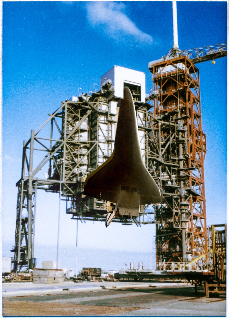 Source: 16streets.com (James MacLaren) In my opinion, this photo montage provides a clear and very interesting size comparison, even the position of the orbiter is not 100% correct.
__________________
Greetings from Germany Manfred Under construction: Launch Pad 39A with Challenger STS-6 (1:144) Last edited by spacerunner; 04-10-2022 at 08:23 AM.
|
|
#2623
04-15-2022, 04:49 PM
|
||||
|
||||
|
Hello everybody,
and so now back to the Payload Canister, which I had already started in February, and for which I had already constructed a Paper Kit in my Reply #2568 before I started with the Transporter, which is now finished and waiting for the canister. 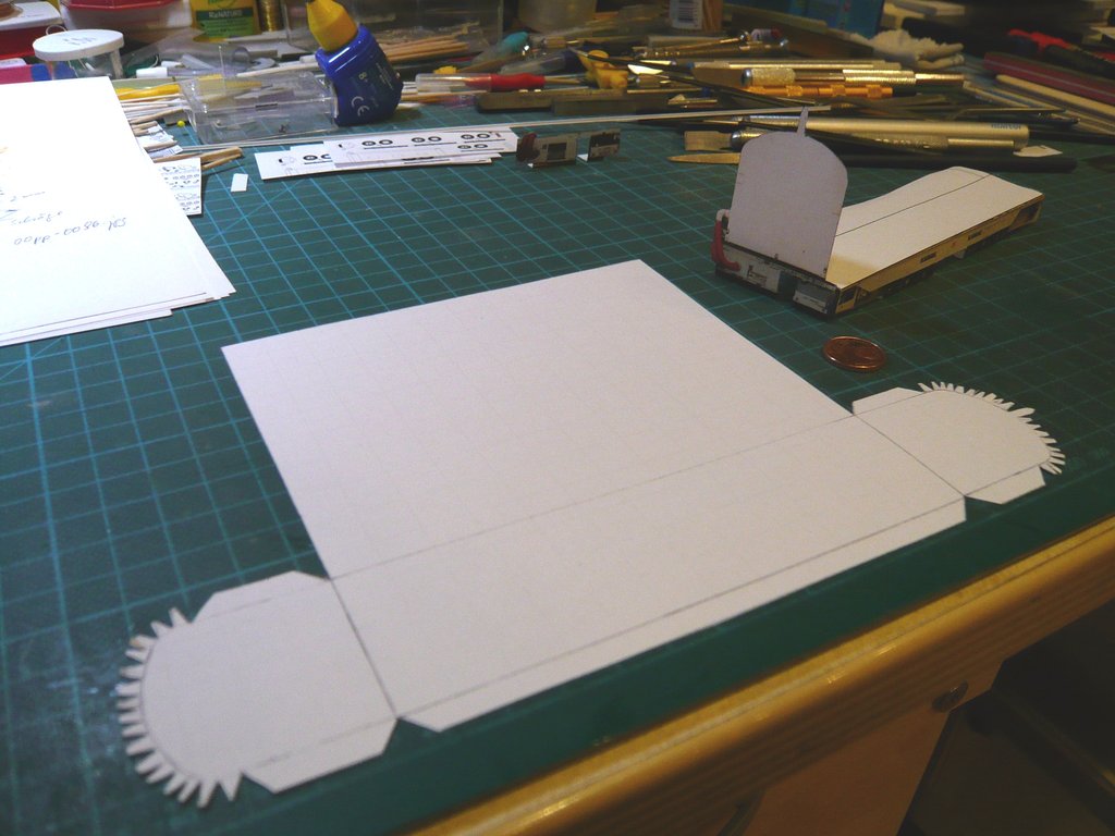 In the meantime I have further modified this canister shell and first attached the NASA Worm logos to all sides.  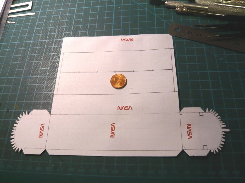 Then I tried with the help of various photos to get an overview of the canister details , of which there are quite a number, such as various Ladders and Railings, bizarre Rod linkages, Mounts, Struts and Hinges with what the Canister Payload Bay Doors let open and lock, as well as various Panels and Doors,  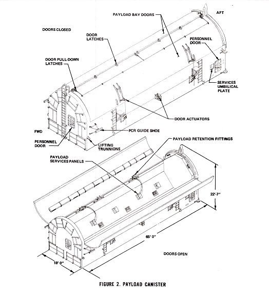 Source: NASA Conference Publication 2342 Part 2 (M. E. Donahue) which can be seen more clearly in these zoomed photos.  Source: NASA (STS-124)  Source: NASA (STS-135) Since the construction of the canisters remained almost unchanged during the Shuttle program, these details were also present on the canisters of the first missions and are therefore relevant for scratching. Since I have certain reservations regarding attaching those tiny details onto a canister made of paper I'm thinking about the possibility of scratching the canister out of a thin Styrene sheet (0,1 mm), which then could be printed with the finest details, as long as my Canon printer would be able to do it, which should at least be worth a try.  Has anyone of you tried it before?  But since one can print onto Decal Foil too, it should work somehow, I hope so.
__________________
Greetings from Germany Manfred Under construction: Launch Pad 39A with Challenger STS-6 (1:144)
|
|
#2624
04-17-2022, 08:56 AM
|
||||
|
||||
|
Hello everyone on Easter Sunday,
before I'll try then to print out the parts for the Payload Canister on a thin Evergreen Sheet Styrene (0,13 mm),  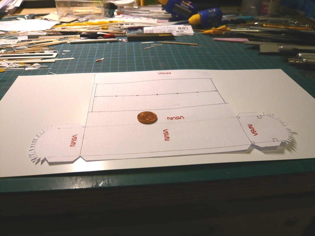 I want to try gluing my Paper Kit together first to get a feel for the size of the canister. But as soon as I cut out and folded the folds on the curves of the front and back wall, I quickly noticed that handling this unstable paper sleeve is anything but easy, let alone when gluing it ...  Somewhat thicker paper would certainly be better suited for this. Somewhat thicker paper would certainly be better suited for this.  That's why I changed my plan and removed the folds on the curves. Instead, I will use Balsa parts (2 mm) for stabilization, which will also serve as an adhesive edge for the Payload Bay Doors. 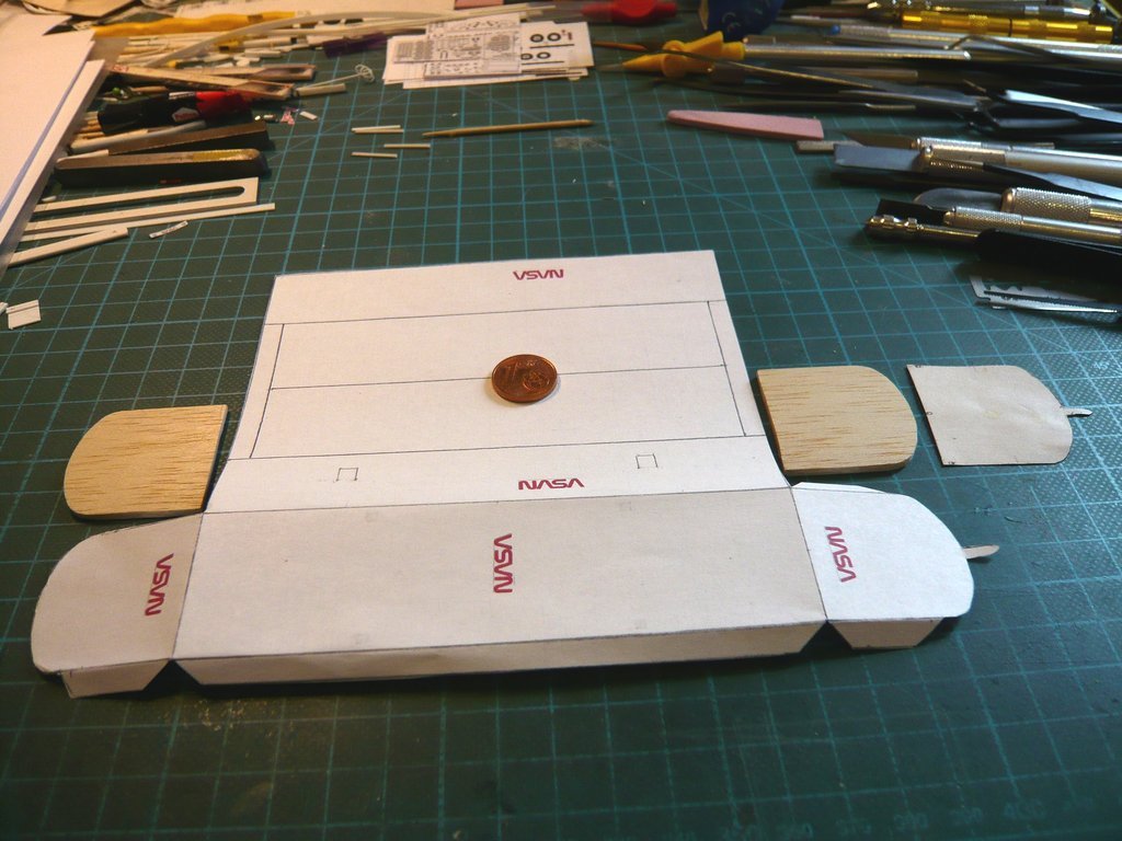 For the same reason I will then also stiffen the bottom and side walls with Balsa in the hope that this will make the canister more stable. 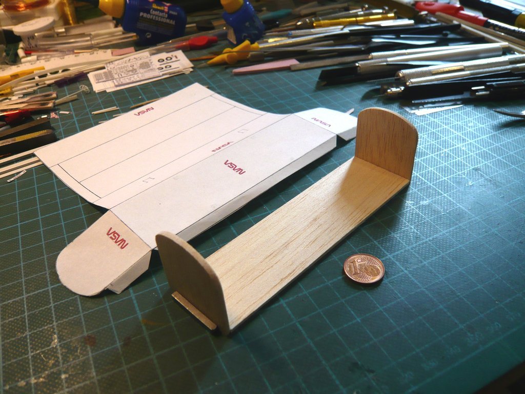 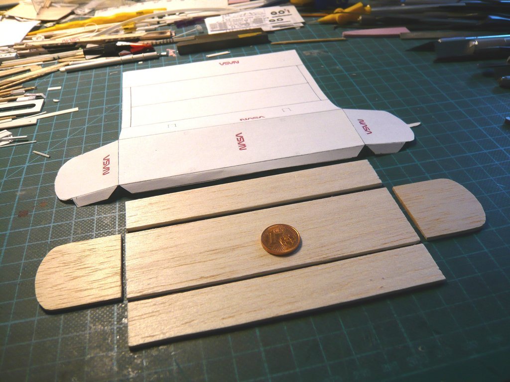 So much for today with my first preparations. Now I wish everyone further 
__________________
Greetings from Germany Manfred Under construction: Launch Pad 39A with Challenger STS-6 (1:144)
|
|
#2625
04-20-2022, 10:56 AM
|
||||
|
||||
|
Hello everybody,
but as is so often the case, the devil is in the detail, whereby I take it usually very exactly, sometimes also too exact,  but what the heck. but what the heck.  And so, looking at original photos, I've noticed certain differences in the top curves of the front and back of the Payload Canister. I was surprised by this photo here at the beginning of the shuttle program, where one can see these strange ("earlike") can see extensions similar in shape to the orbiter's OMS pods, meaning the "humps" (Orbital Maneuvering Systems) found on either side of the shuttle's tail are, which initially has irritated me quite a bit. 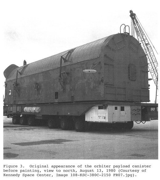 Source: Orbiter Payload Canisters (HEAR NO. FL-8-11-I) This photo comes from a very interesting source that I unfortunately came across only recently, late but not too late! In this documentation is described, among other things, that these originally designed "ear-like" extensions at the end of the canister, called "mouse ears" by the staff,  had been removed already at both canisters at the start of the shuttle program, which put my mind at rest. had been removed already at both canisters at the start of the shuttle program, which put my mind at rest. In order to find out more and to be on the safe side, I looked again for STS-6 photos, specifically to take a closer look at these curves on the front and back, especially since their shape deviates from the semicircular shape of the Payload Bay of the canister, which can only be seen on closer inspection in the following photos of the STS-6 canister.  his photo from the Vertical Processing Facility (VPF) shows the opened Payload Canister with NASA's TDRS satellite, transported into space by Challenger during the STS-6 mission. Source: forum.nasaspaceflight.com (Ares67, STS-6) On this image section I have circled the passages that are meant. On it you can see that the outer bulges of the front wall (Forward Bulkhead) protrude slightly over the curve of the Payload Bay, but in any case they did not have any protruding "mouse ears". 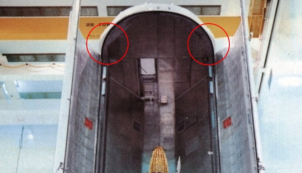 This photo shows the opposite back side (Aft Bulkhead) of the canister, where one can clearly see that these bulges are more pronounced. Source: forum.nasaspaceflight.com (Ares67, STS-6) A distinctive feature of this side, with which one can easily distinguish it from the front wall, is the tail (Spike), which again mimics the shuttle, which contains the upper door seal control panel. 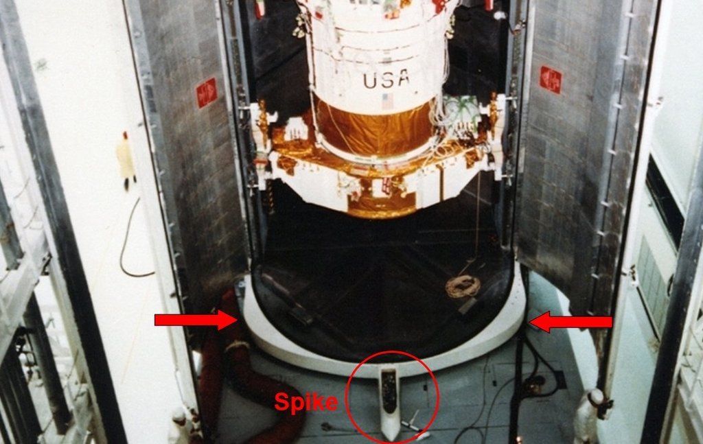 With this side the canister is standing in the upright transport position (Vertical Transport Mode) on the transporter as can be seen in this image. 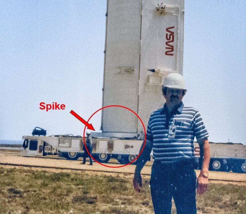 Since the Payload Bay Doors are not flush with the prepared balsa parts of the front and back wall, I cannot glue the cover of my Paper Kit onto it as previously planned, which is why I will inevitably have to modify these parts and the construction of the canister somewhat. So let's see what can be done.
__________________
Greetings from Germany Manfred Under construction: Launch Pad 39A with Challenger STS-6 (1:144)
|
|
#2626
04-20-2022, 02:14 PM
|
||||
|
||||
|
Don’t the upper portions of the fore and aft bulkheads of the canister match the shapes of the fore and aft Orbiter payload bay bulkheads? They’re shaped differently, so wouldn’t the canister bulkheads be similarly shaped?
|
|
#2627
04-21-2022, 05:35 AM
|
||||
|
||||
|
Hello David,
the upper portions of the fore and aft bulkheads of the Canister match the shapes of the fore and aft Orbiter Payload Bay bulkheads, as does the shape of the canister and orbiter Payload Bay Doors. Only the shape of the fore and aft bulkheads of the Canister is slightly different, which can be seen in these photos for the canisters of STS-41C 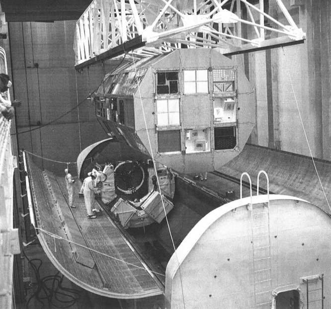 Source: Orbiter Payload Canisters (HEAR NO. FL-8-11-I) and in the Hi-Res. of STS-80 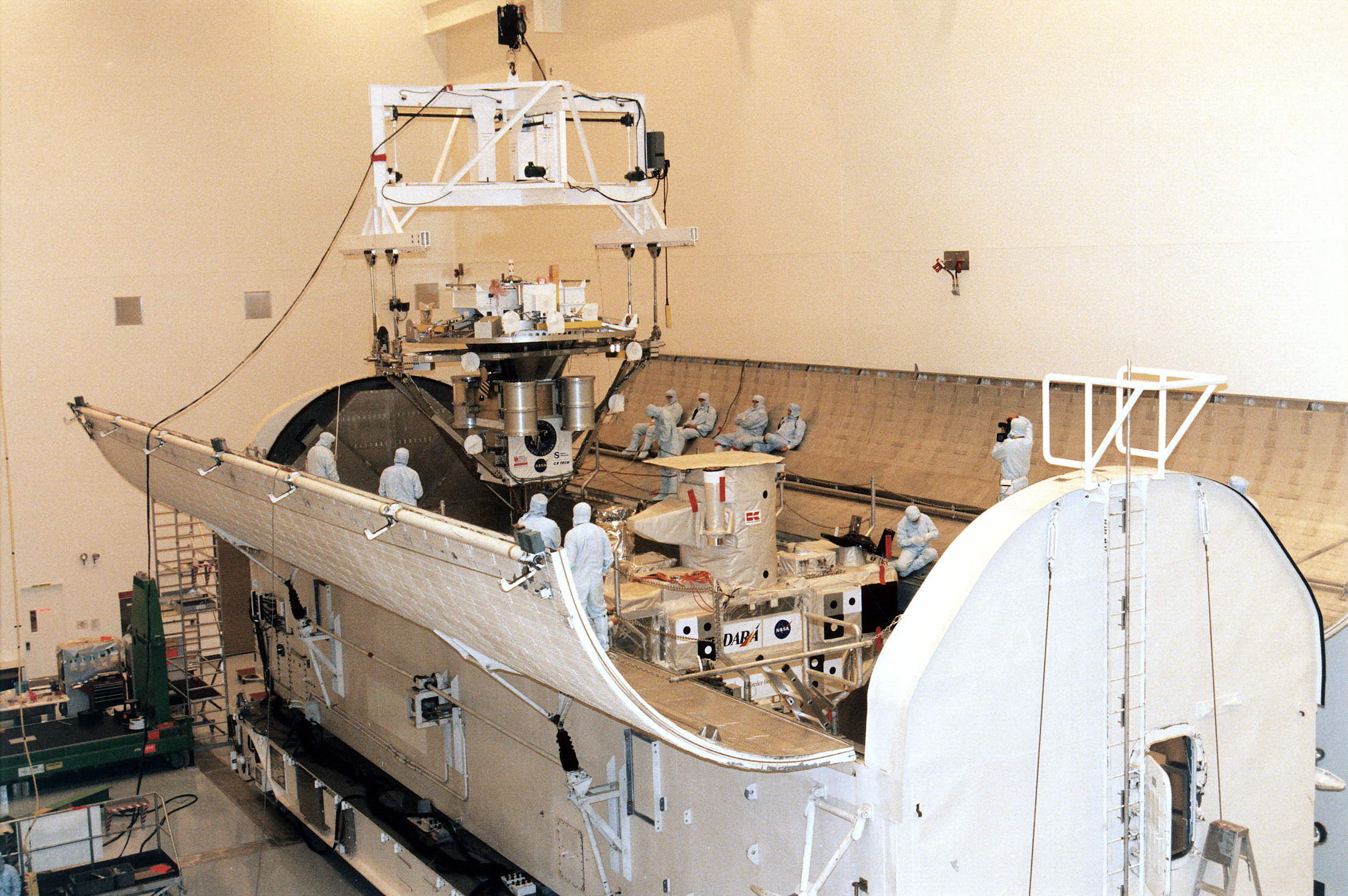 Source: wikimedia.org (STS-80) and STS-132.  Source: mediaarchive.ksc.nasa.gov But you have to look very carefully already.
__________________
Greetings from Germany Manfred Under construction: Launch Pad 39A with Challenger STS-6 (1:144)
|
|
#2628
04-22-2022, 04:14 PM
|
||||
|
||||
|
Hello everybody,
as can be seen in the last photos, the front and back of the Payload Canister differ in shape, albeit only slightly, at least they are not identical. The most reliable template for the back (Aft Bulkhead) of the canister with the spike is shown in this photo which comes from the STS-9, Source: forum.nasaspaceflight.com (Ares67, STS-9) as is this photo of the front (Forward Bulkhead), whose outline isn't quite as evenly rounded as one can see here. Source: forum.nasaspaceflight.com (Ares67, STS-9) The outlines of both sides I've drawn and cut out on Balsa (2 mm), as well as the Payload Bay Doors, which are rounded semicircularly. These parts are each glued onto the front and back and serve as an adhesive edge for the outer shell of the doors. 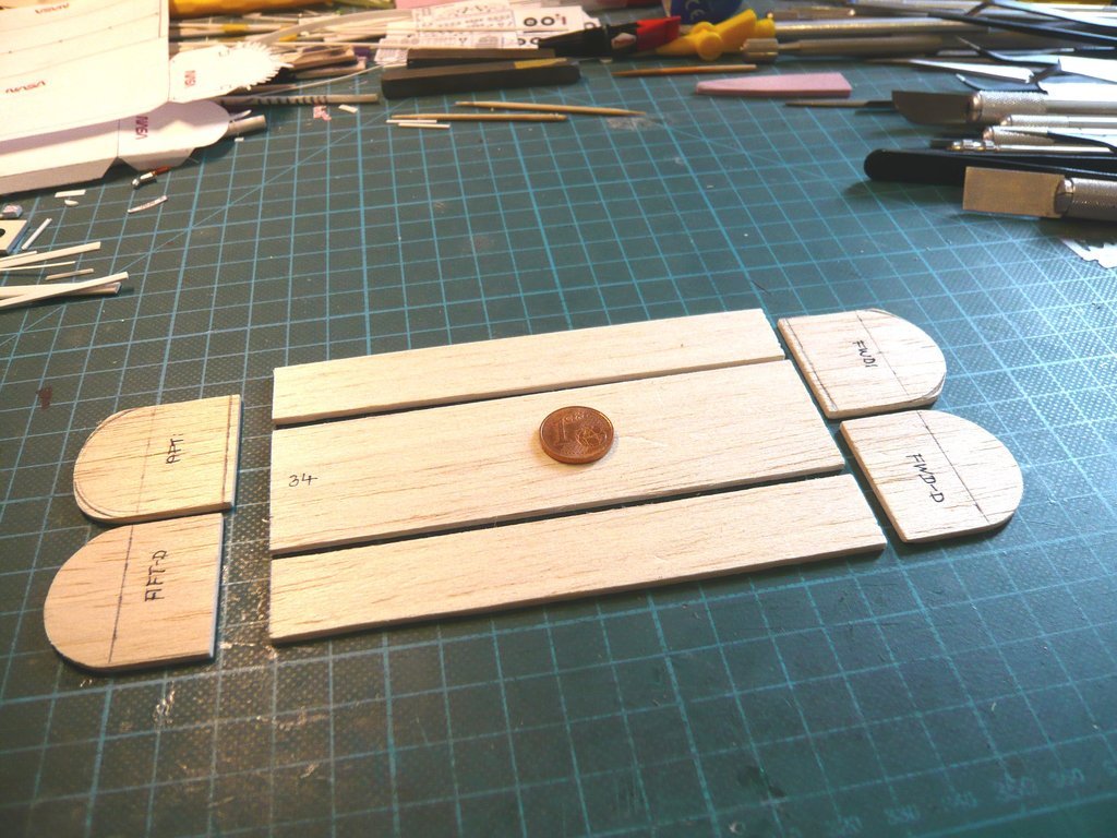 After I had cut out the recesses for the side walls of the canister from the door supports, 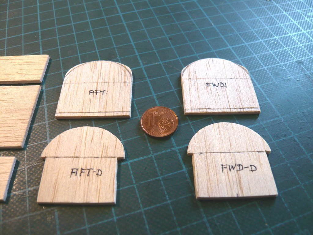 I've put the parts that belong together on top of each other, which makes the different curves of the front and back even clearer. 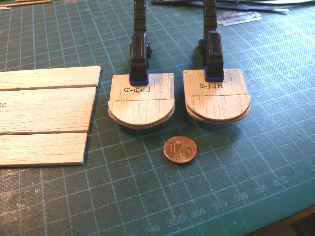 And then I've put the parts together to form the canister, which should be stable, and looks pretty neat. 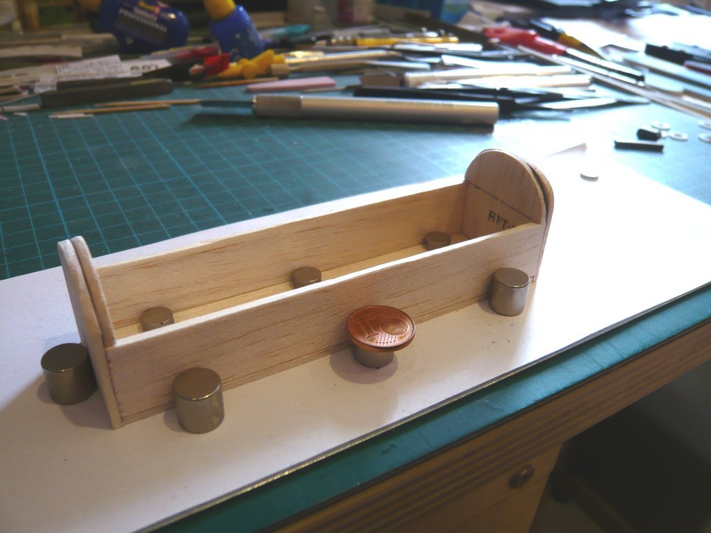 Next I will now try to print these parts on an Evergreen Sheet Styrene (0,13mm) in the hope that it will work, then we'll see.
__________________
Greetings from Germany Manfred Under construction: Launch Pad 39A with Challenger STS-6 (1:144)
|
|
#2629
04-26-2022, 04:25 PM
|
||||
|
||||
|
Hello everybody,
since I also came across some drawings with detailed views of the sides of the canister in part of the documentation Orbiter Payload Canisters (HEAR NO. FL-8-11-I), I decided without further ado to abandon my previous plan of gluing the coherent sleeve (Paper kit) and instead to create detailed Sides separately and glue them onto the Balsa framework of the canister. Now that I know where the details go, I can choose which ones to scratch and save a lot of drawing work. Before I'll try printing the parts on an Evergreen Sheet Styrene (0,13mm) I will first print them out on paper to be able to check the fit of the parts on the framework. The first thing I did was to determine the semi-circular outline of the Payload Bay Doors to be able to glue the curved covering of the canister later onto the side walls and the inner Supporting walls at the Forward & Aft Bulkheads. To do this, I fixed again a thin brass wire closely around the curve of a supporting wall with magnets in order to be able to determine the length for the flat pattern of the contour, which is the simplest solution. 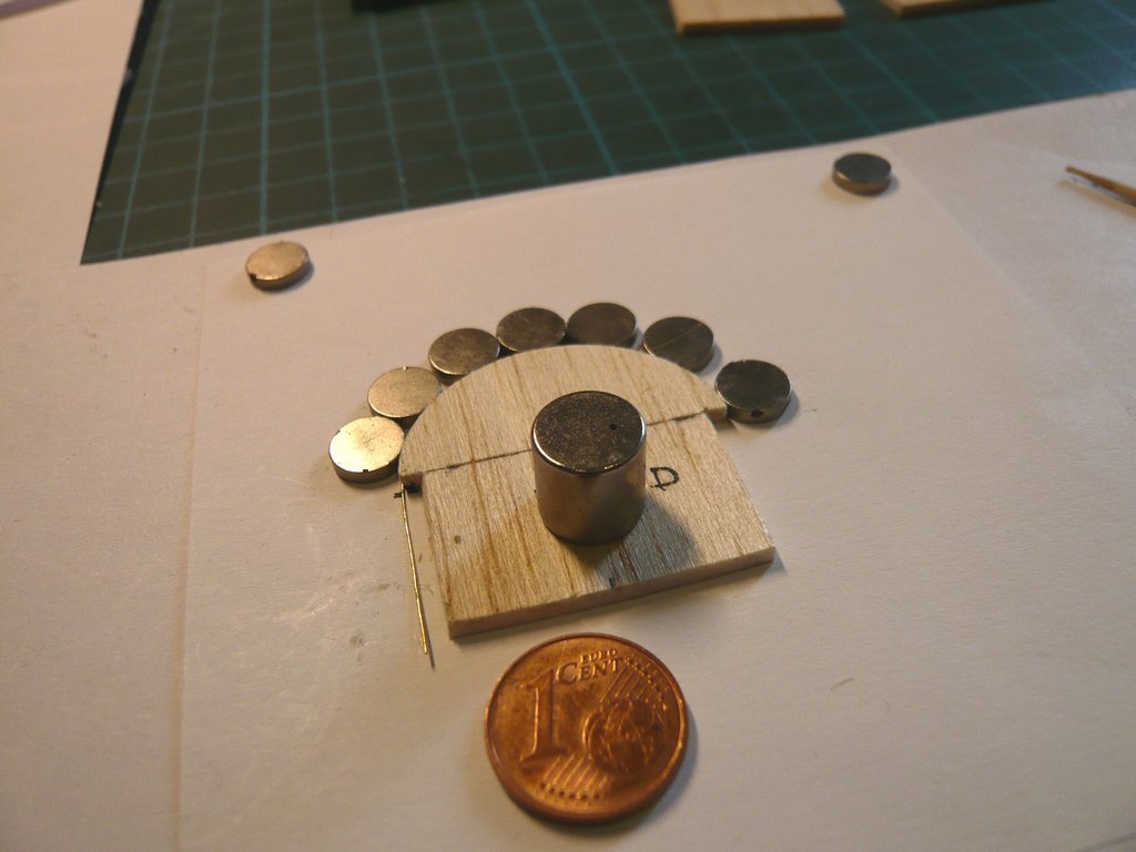 And this is what the flat pattern looks like. 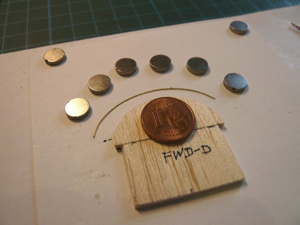 It is approx. 50 mm long, so the part for the doors should have dimensions of 120 mm x 50 mm, making the semicircular PLC doors. 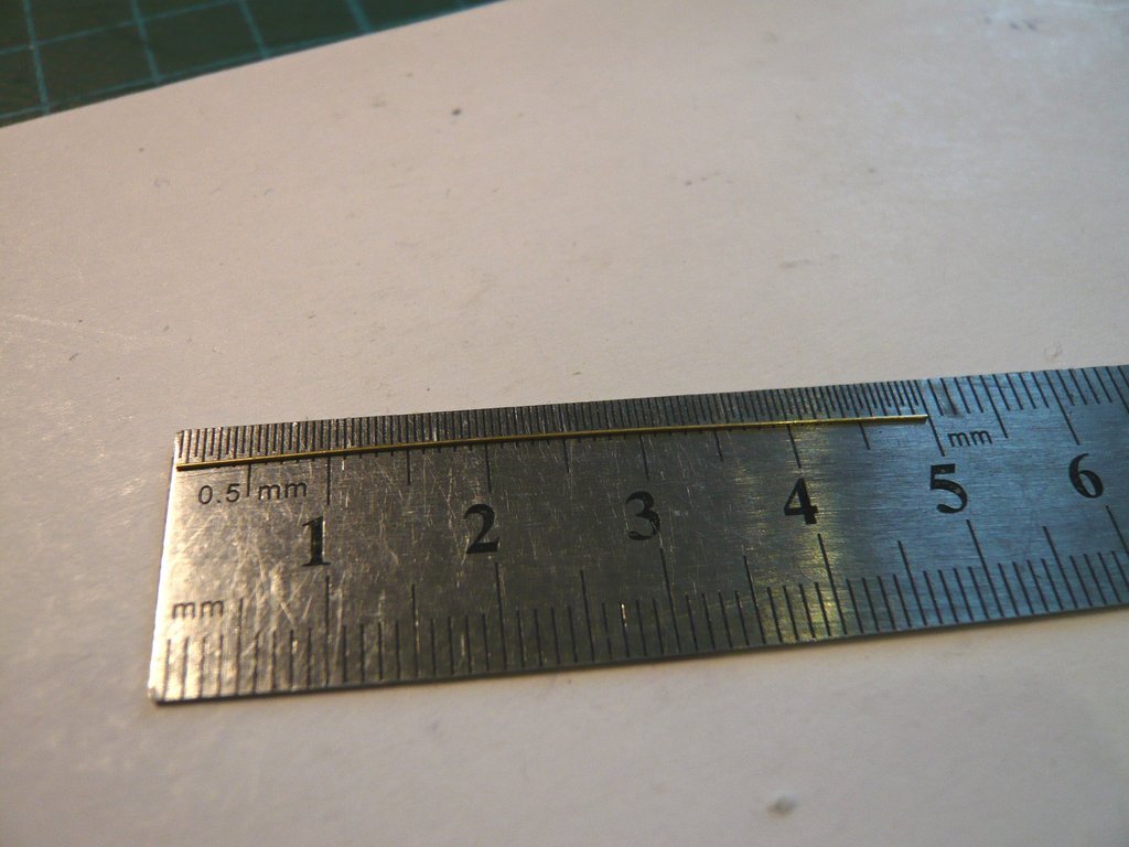 Based on the drawings, I was able to reconstruct the doors of the canister from the top and side views, which was not that easy, since e.g. the position of the semicircular brackets of the Door Actuators of both doors had to be projected into the plane. Source: NASA Conference Publication 2342 Part 2 (M. E. Donahue) When preparing the parts, I first retouched away all those details of the drawings that are outside the canister shell, such as ladders, railings, cables, etc., so as not to see them twice afterwards, and have only marked their base points. And this is how the finished flat pattern of the doors now looks like, 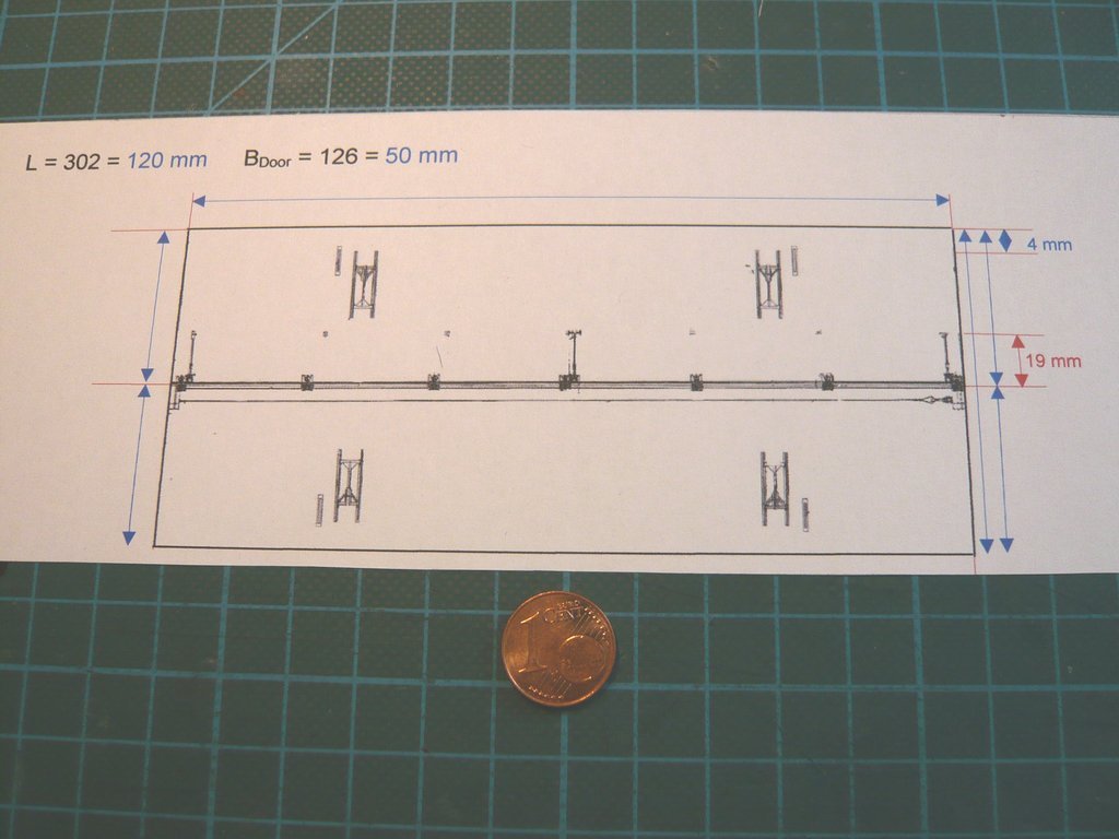 that I printed out on paper and cut out,  then have rolled in, then have rolled in, 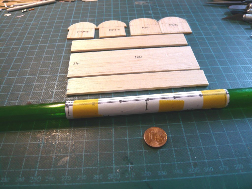 and rolled it out again after a while. 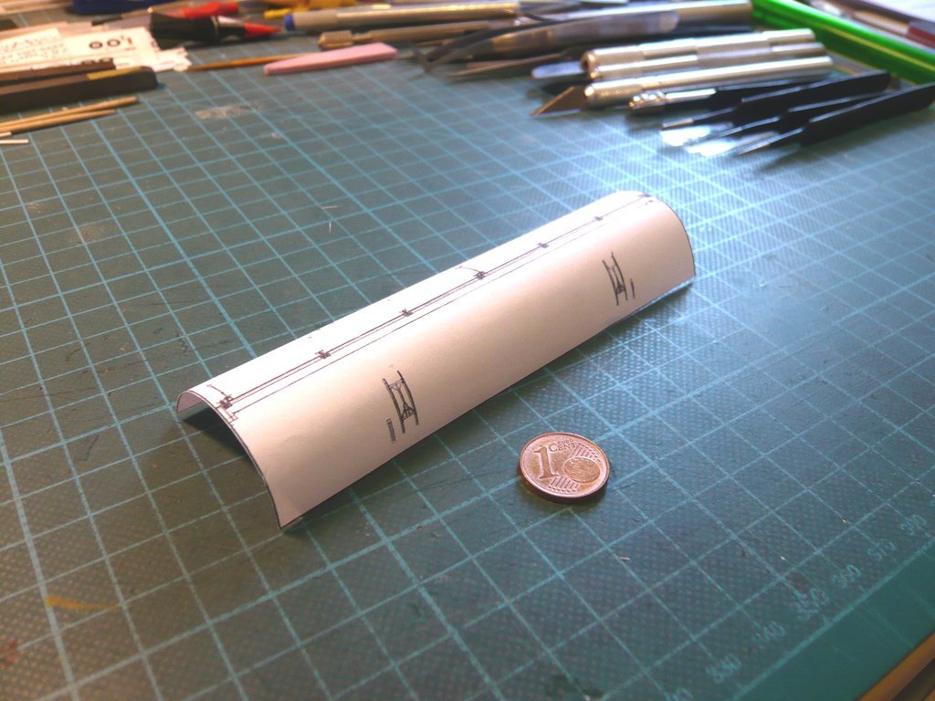 The test fitting of the doors on the canister looked nearly perfect and made me quite confident about the further procedure. 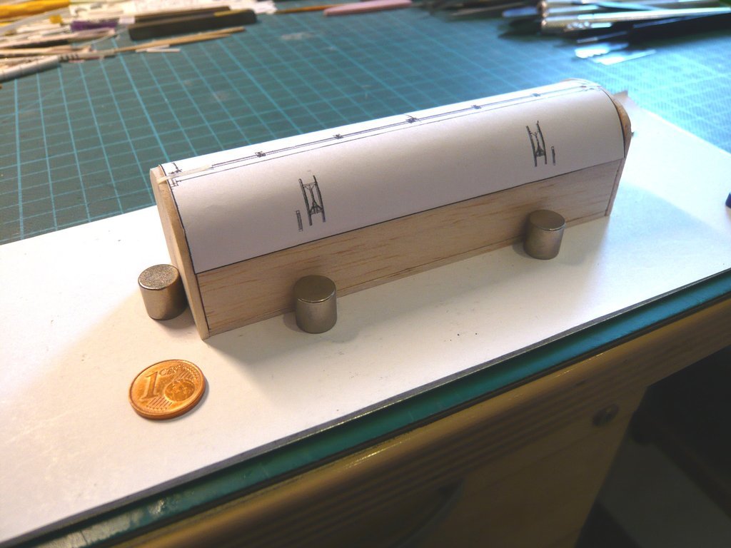 This includes further drawings, such as the Forward & Aft Bulkheads, but again without the ladders and railings located there,  as well as the Port Side & Starboard Side with the remaining parts of the Door Actuator systems, whose Actuator Screw Jackets were removed again, as well as the ladders too. And of course the Bottom of the canister must not be missing (below). 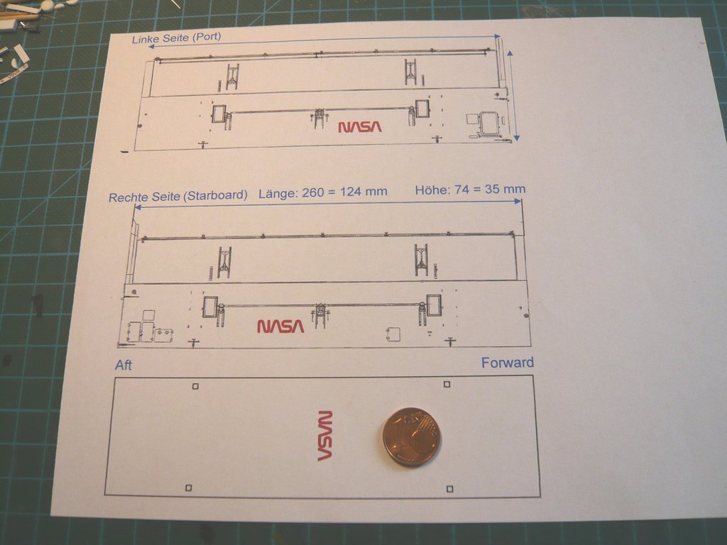 So far for today, tomorrow is still another day too.
__________________
Greetings from Germany Manfred Under construction: Launch Pad 39A with Challenger STS-6 (1:144)
|
|
#2630
04-28-2022, 05:05 PM
|
||||
|
||||
|
Hello everybody,
today I started with the structural work of the Payload Canister and first glued the two side walls with the bottom. In doing so it was important to ensure that the walls were vertical, flush with the floor and couldn't slip, which is why I clamped them in using my proven Magnetic clamping Technique. 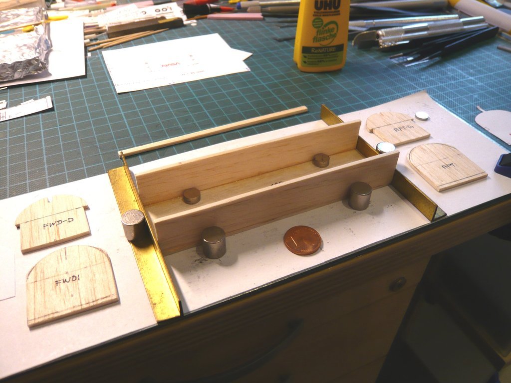 Then I glued the Forward and Aft Bulkheads on both sides. To stabilize both sides in the longitudinal direction and to later support the thin Payload Bay Doors (0,13 mm), I've also intended a spacer bar (2 mm x 4 mm x 120 mm) made of Balsa, which was temporarily held by the supporting walls during the gluing and acted as a spacer, for which I had cut out a corresponding recess from the two supporting walls.  After checking that the previously glued parts were correctly seated, I then glued both supporting walls from the inside onto the front and back and fixed them with clips, and glued in the spacer bar. 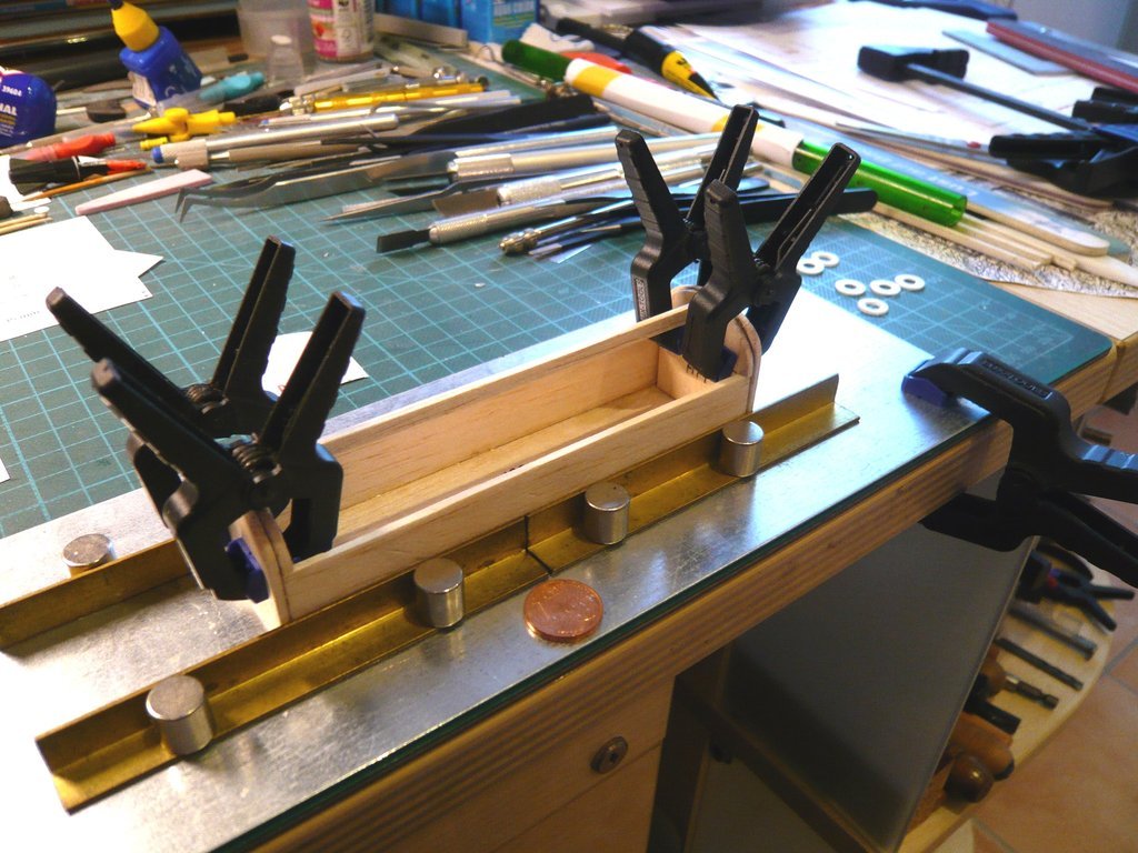 This completed the structural work of the canister,  and I was able to try on the doors, which matched again, as did the cover of the Forward Bulkhead. 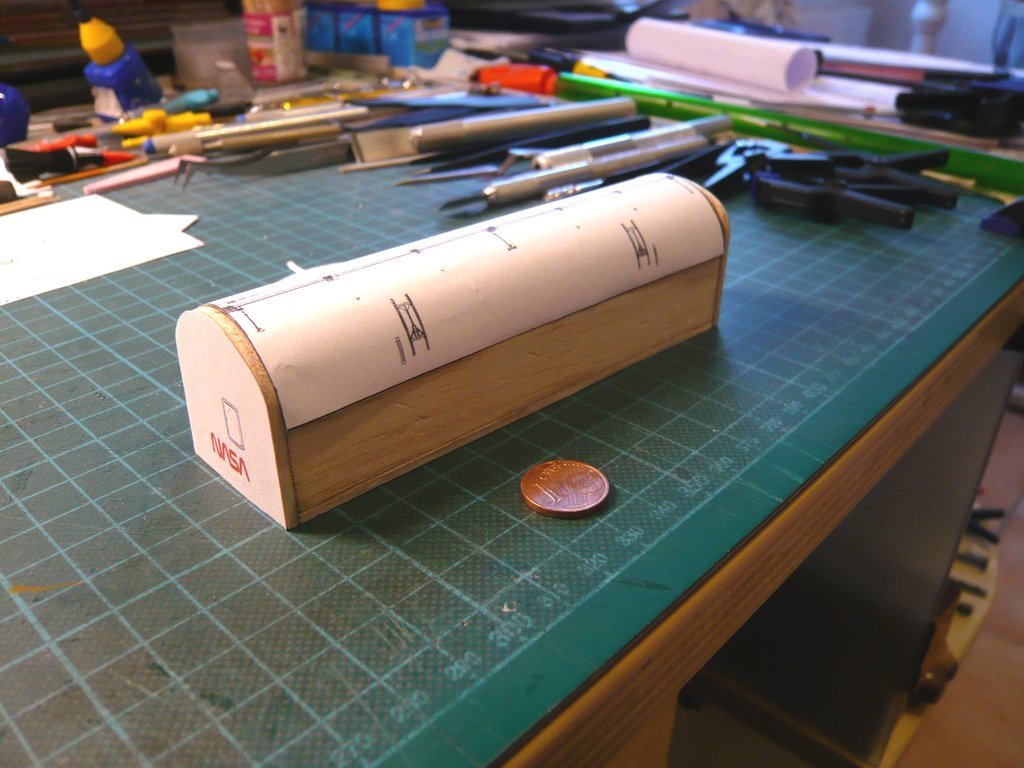 At this point it should be mentioned again briefly that the Canisters were labeled with same designations as the Orbiter: the Starboard Side (right), and the Port Side (left). In order to get an overall impression, I have now also covered the walls all around, here with a view of the Port Side and the Forward Bulkhead, 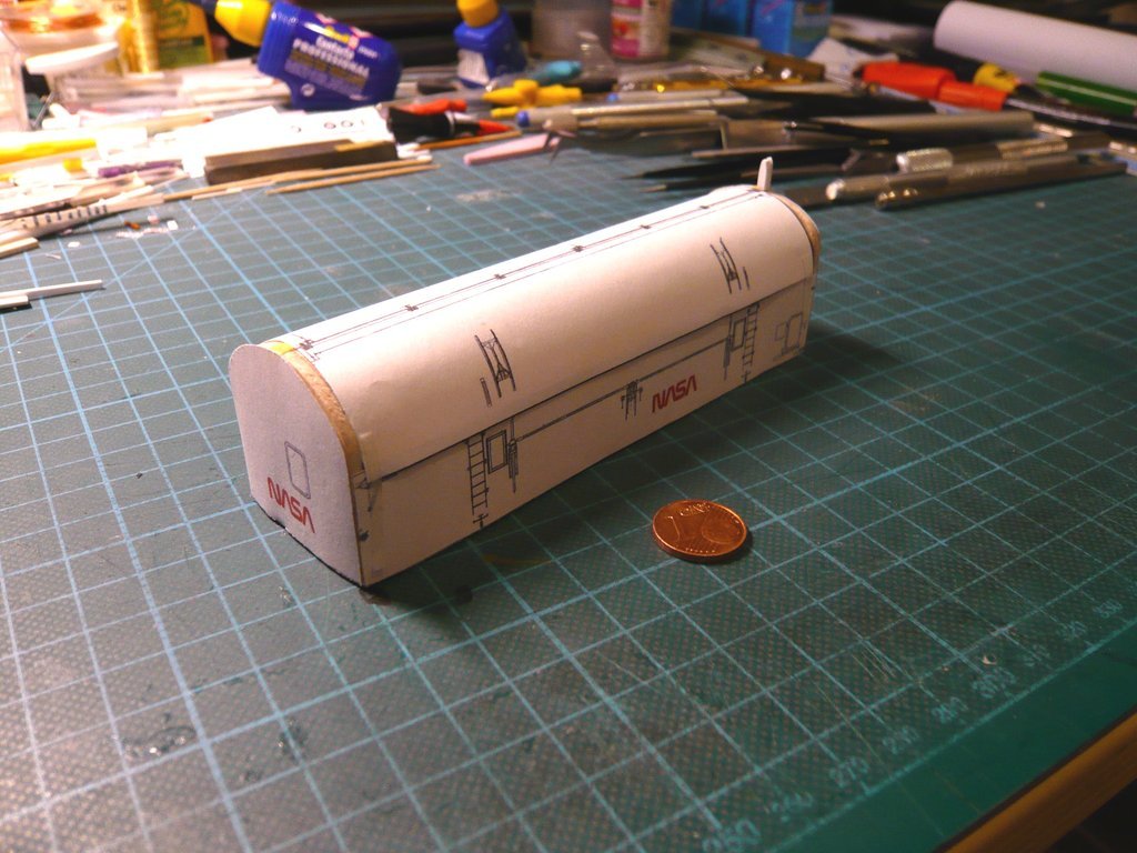 and here a view of the Starboard Side and the Aft Bulkhead with the Spike. 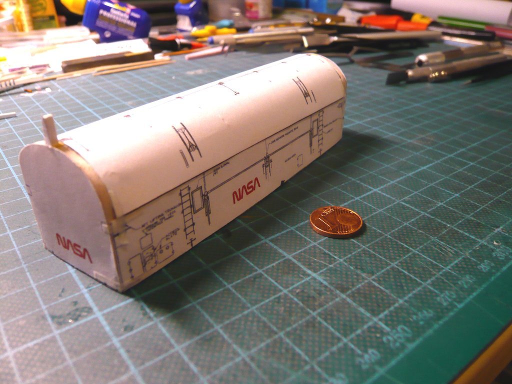 Well, and then I was curious and of course I wanted to see what the Canister looks like on the Transporter, and here it is, even if only as a provisional arrangement, here with a view of the Port Side,  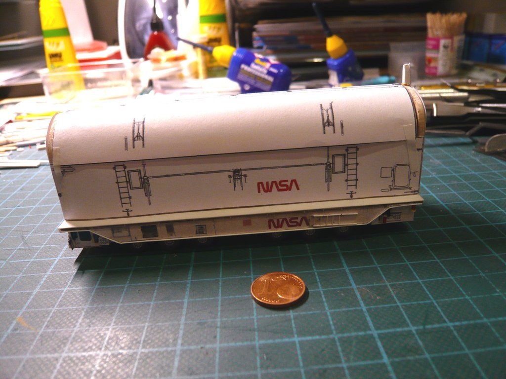 and on the Starboard Side. 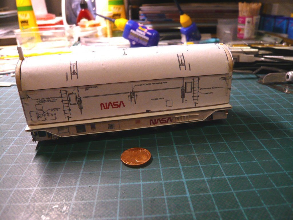 And this is the view of the transporter approaching the Launch pad with upright standing canister. 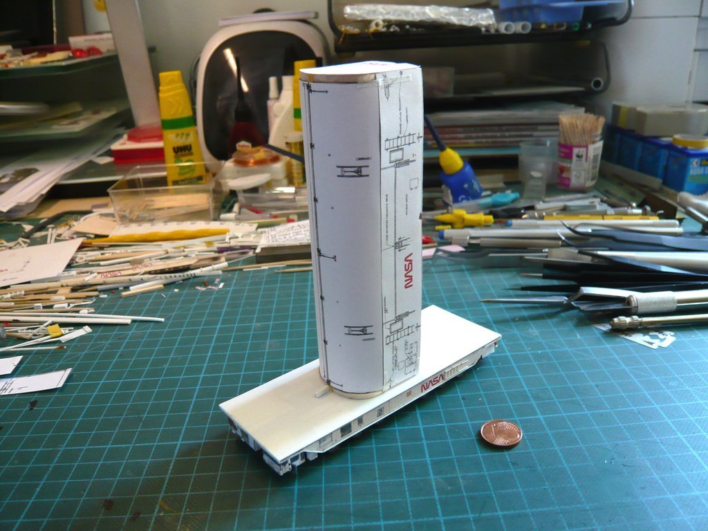 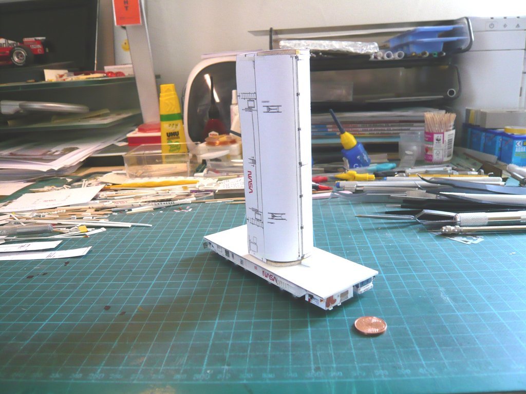 As an interim conclusion, it can be said that the images are promising despite the still unfinished state of the canister and encourage me to continue,  although there is still a lot to do before final completion the Sheet Styrene version, but it is after all a decent result. although there is still a lot to do before final completion the Sheet Styrene version, but it is after all a decent result.
__________________
Greetings from Germany Manfred Under construction: Launch Pad 39A with Challenger STS-6 (1:144)
|
 |
|
|


 Linear Mode

