


|
|
|
#2681
 08-17-2022, 01:52 AM
|
||||
|
||||
|
After removing the two blocks, the remaining sides of the plate were also be glued,
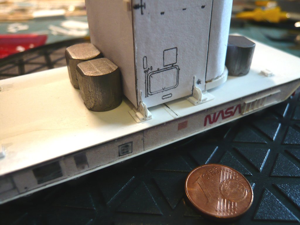 whereby the canister was definitively fixed by the transport plates.  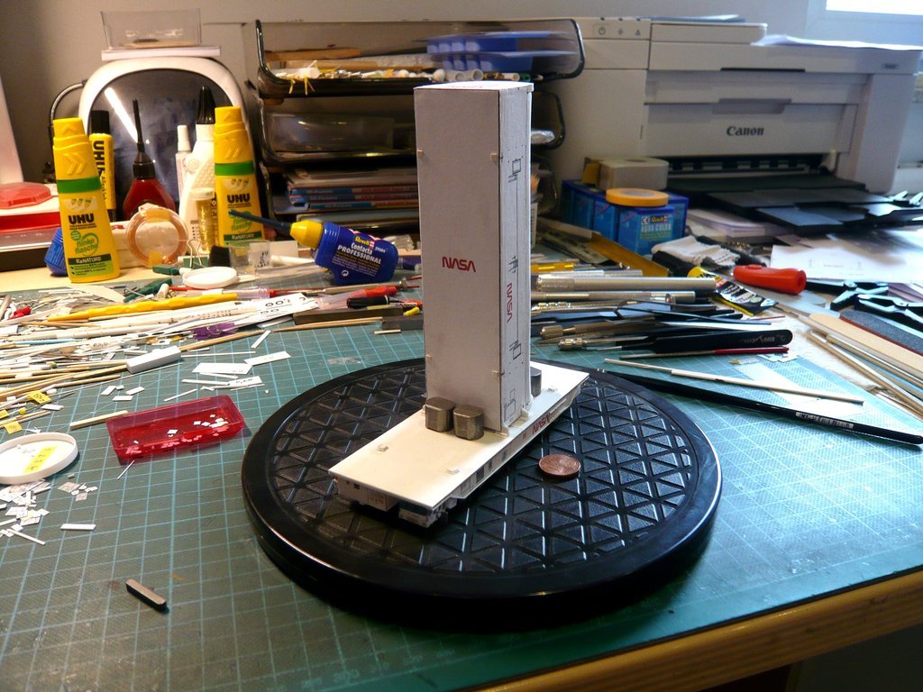 Here is a view onto the front side. 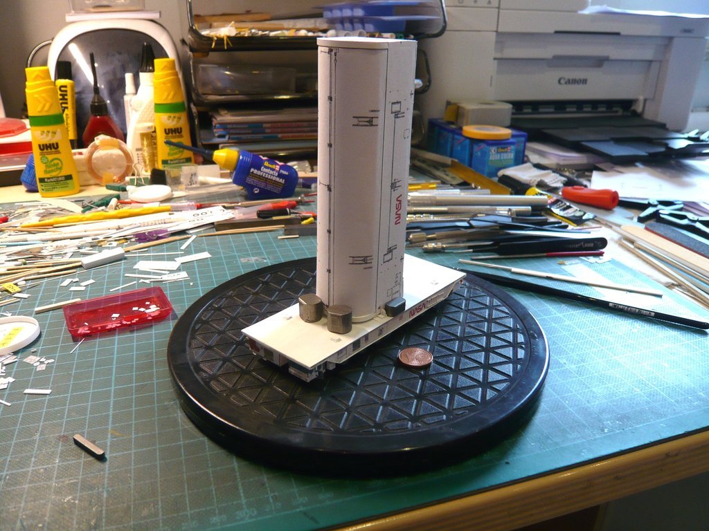 Then all the blocks could be removed and the Sliding shoes were placed on the plates to get an overall impression, 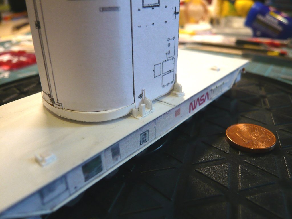 what is impressive from all sides,  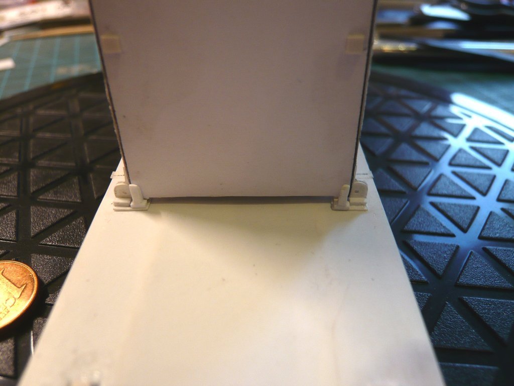 and has successfully passed my, as always, critical final check, wherewith my angelic patience has paid off at the end too.  Thank God! Thank God!  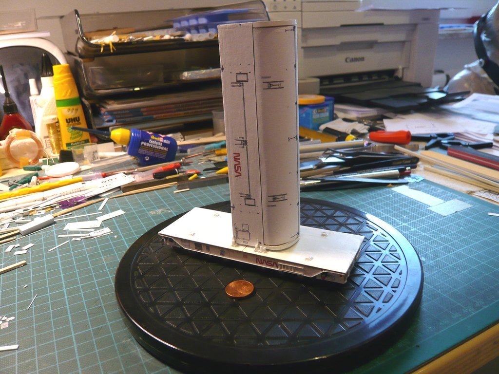 Now I can calmly set out to scratch some more details on the Payload Canister, like there were the Door Latches of the Payload Bay Doors and their Door Actuator Pneumatic Drives, as well as ladders, platforms, doors, etc., wherewith I will definitely have to do with for a while ...  
__________________
Greetings from Germany Manfred Under construction: Launch Pad 39A with Challenger STS-6 (1:144) 
|
|
#2682
08-19-2022, 05:23 PM
|
||||
|
||||
|
Hello everybody,
now that I've dealt with the Vertical transportation mode long enough, the Horizontal transportation mode should also be brought into the picture once again.  To do this, all Hold-down Clevises as well as the Sliding shoes were usually dismantled and put next to the canister, 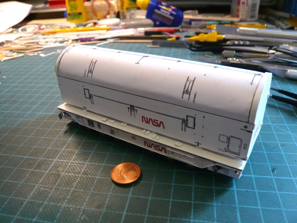 as one could see in this image,  Source: NASA (STS-132) which I simulated just for fun.  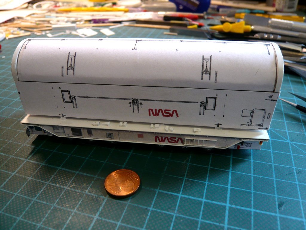 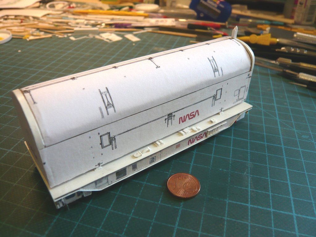 After this little Milestone, I got all the parts to safety.  The bizarre Tie-down Lug Plates are only glued to the canister at the end anyway and must not get lost. The bizarre Tie-down Lug Plates are only glued to the canister at the end anyway and must not get lost.  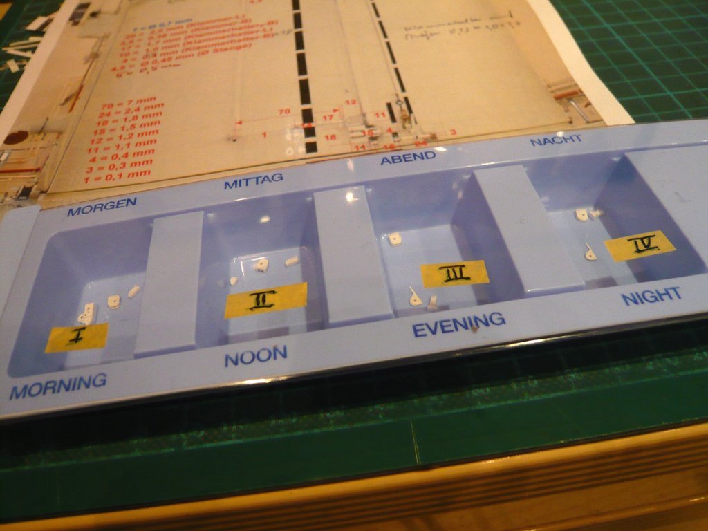 And the cleared transporter was parked in the cupboard until further notice and is waiting there for the canister to be completed. 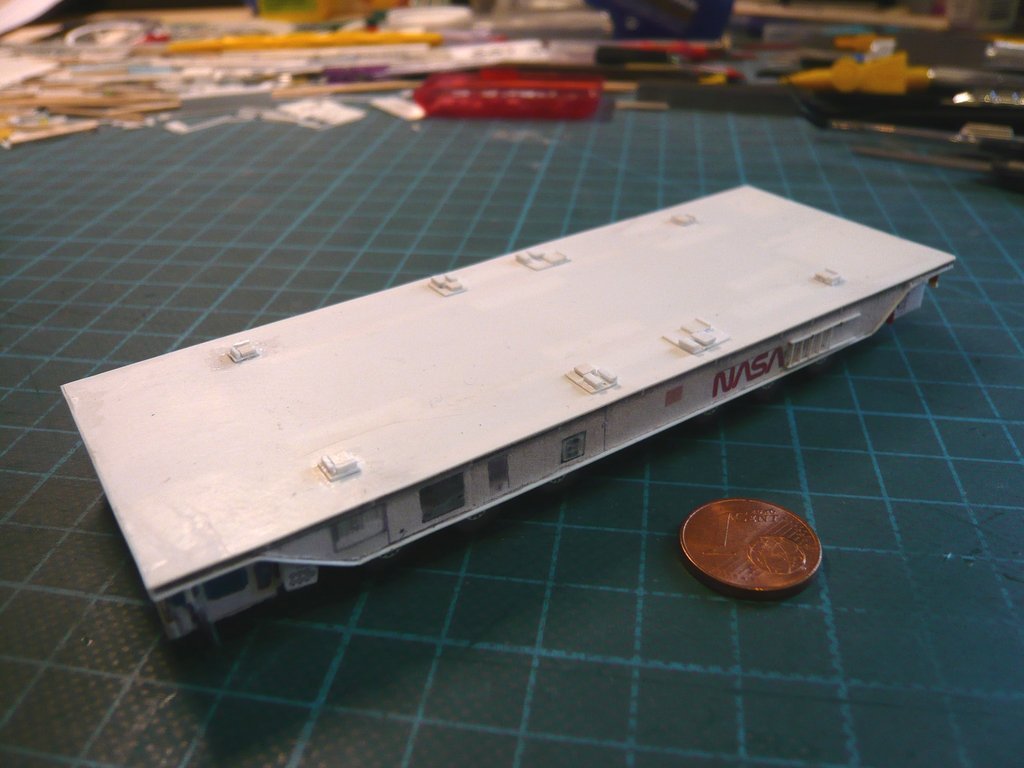 As already announced, I can now take my time to turn to some more details on the Payload Canister what can be seen in this image. Let's start with the Door Latches of the Payload Bay Doors, which can be seen in this drawing, 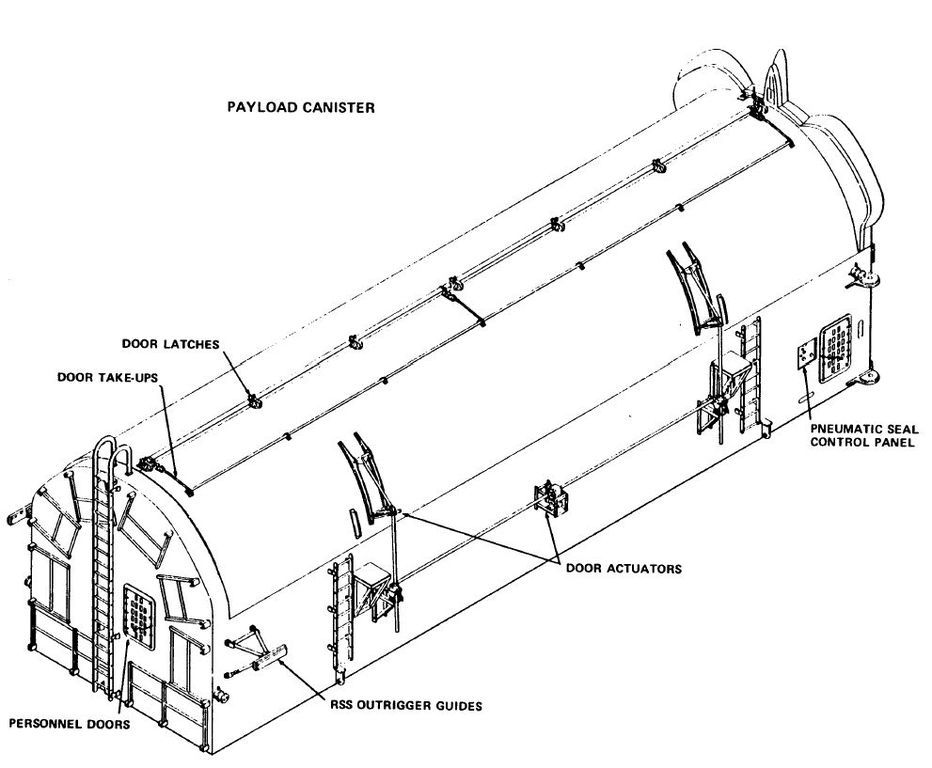 Source: NASA Conference Publication 2342 Part 2 (M. E. Donahue) and whose structure can be studied in detail on this photo at high magnification (2000 x 3008).   Source: NASA (STS-114) The Door Latch Mechanism could be actuated from either end of the door by a Torque tube that runs the length of the door, on which seven Latch Clamps are attached.  Source: NASA (STS-135) To put it simply, scratching is about a tube with seven clamps that lock in latch mechanisms whose dimensions I first determined, whereby the diameter of the tube was used as reference dimension, which I determined from NASA drawings based on the width of the canister, which is Ø 0,7 mm (1:160). Source: NASA (STS-114) Since these parts are also in the millimeter range and below,  I'm prepared for a lot, which is why I first had to think of a suitable solution with which I'll continue next time. I'm prepared for a lot, which is why I first had to think of a suitable solution with which I'll continue next time.
__________________
Greetings from Germany Manfred Under construction: Launch Pad 39A with Challenger STS-6 (1:144) Last edited by spacerunner; 08-19-2022 at 06:18 PM.
|
|
#2683
08-29-2022, 02:17 AM
|
||||
|
||||
|
Hello everybody,
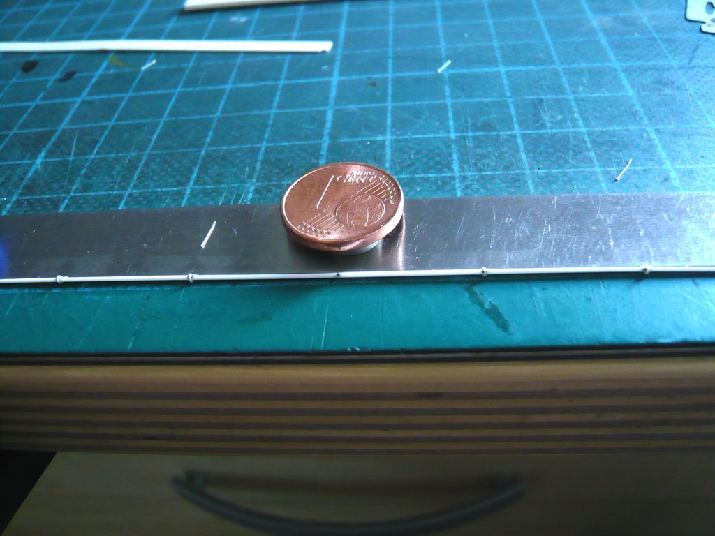
on photos of the canister with the doors closed, one can usually only see the long Torque tube, but only a few details of the seven Door latches, and don't know on which of the two doors where/what is attached. Source: NASA (STS-132) Greater clarity about this one can only obtain from images of the canister with the doors open, whereby it is important when assigning special details from which side you look at the canister, but what you need to know for Scratching.  As one can see in the image below, the long Torque tube and the Swivel latches attached to it are on the door in the foreground, without knowing, however, which of the two Payload Bay Doors it is.  Source: NASA (STS-135) This fact gave me a headache at first, what I've only gradually understood after analyzing several detailed photos about. As one can see in this image, according to the NASA definition, one is looking at the Forward bulkhead of the canister, on which one can see the door gap. The left canister door is the so called Port Side Door, and the right door is the Starboard Side Door, on which the Torque Tube is attached, that is connected with the seven Door Latches.  Source: NASA (STS-135) After realizing this, I thought about the best way to scratch these Door Latches.  For the Swivel latches, I first remembered the small Channel profile (0,7 mm x 1,2 mm) in the following image, from which I've cut off a first clamp with a razor blade, which unfortunately turned out to be too small for the Round bar (Ø 0,7 mm).  However, since I had determined in the meantime that the Swivel latch should have a length of 2 mm, I opted for a Evergreen H profile (1,8mm x 2,0mm) from which I filed off the webs on one side,  resulting in a suitable latch of sufficient height to cover the rod as can be seen in the photos with the doors closed. 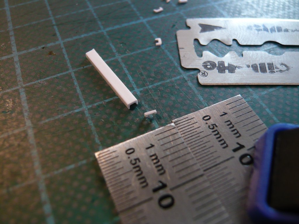 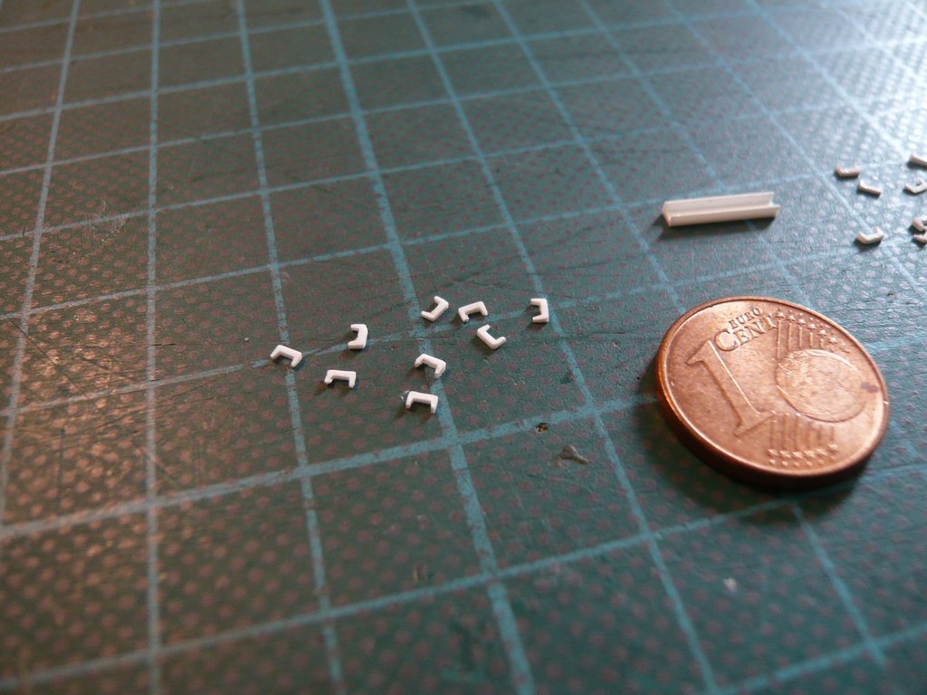 And this is what the first test fitting of the rod with the seven latches on the canister looked like, which looked pretty good. 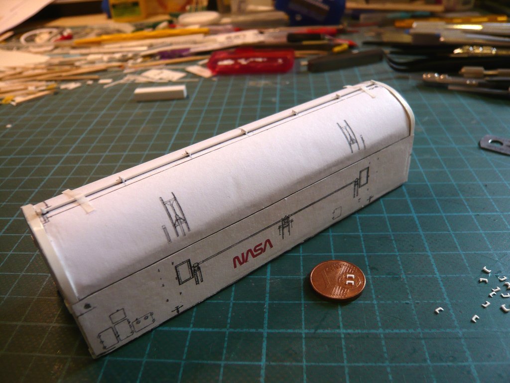 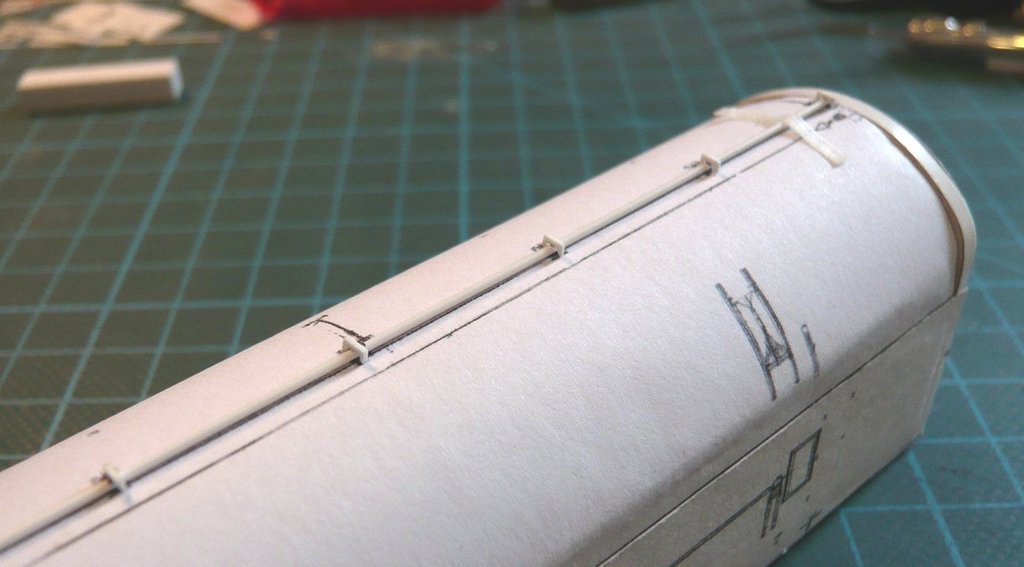 As one can see in this image, there are two small boxes next to the swivel latches that protrude onto the Port Side Door.  Source: NASA (STS-134) Final clarity about the structure of the Door latches one can get from images like these ones.  Source: NASA (STS-131)
__________________
Greetings from Germany Manfred Under construction: Launch Pad 39A with Challenger STS-6 (1:144)
|
|
#2684
08-29-2022, 02:25 AM
|
||||
|
||||
|
When the doors are closed, the Swivel latches snap into the holders on the Port Side Door, locking the doors.
 Source: NASA (STS-131) As one can see in the image shown at the beginning, these covers on both sides of the swivel latches were sometimes not available, which irritated me at first. However, in Zoom you can see the slanted holder of the swivel latch on the Port Side Door into which the swivel latch engages. Source: NASA (STS-132) This becomes even clearer in the following image with the doors open,  Source: NASA (STS-131) which is why I compared both parts of the Door latch system again. 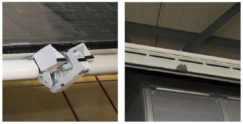 Source: NASA (STS-131) And that's enough of the interesting and, with these enlargements, quite plastic details. My task now was to simplify this system to such an extent that there is still something left of it on a scale of 1:160. The swivel latches were already finished, for their side coverings I've planned small blocks made of Evergreen strips (0,5 mm x 0,5 mm x 1,0 mm), of which I wanted to glue two sticks next to each other on a thin base strip (0,1 mm x 1 mm), which are only then cut off to a length of 1 mm. This image shows the entire again fixed assembly. Due to the minimal dimensions of the parts, all gluing of the latch to the rod should be done with MEK. Only at the end the swivel latch is carefully glued on.  So much for the theory. I have to catch up one more thing. As one could see on the previous photos, the white Torque tube is not continuous, but only its inner Torsion bar, which is exposed on the swivel latches, which I at least wanted to indicate by these black markings.  Well then, let's see if everything works the way I imagine it to.
__________________
Greetings from Germany Manfred Under construction: Launch Pad 39A with Challenger STS-6 (1:144)
|
|
#2685
08-29-2022, 04:11 PM
|
||||
|
||||
|
Hello everybody,
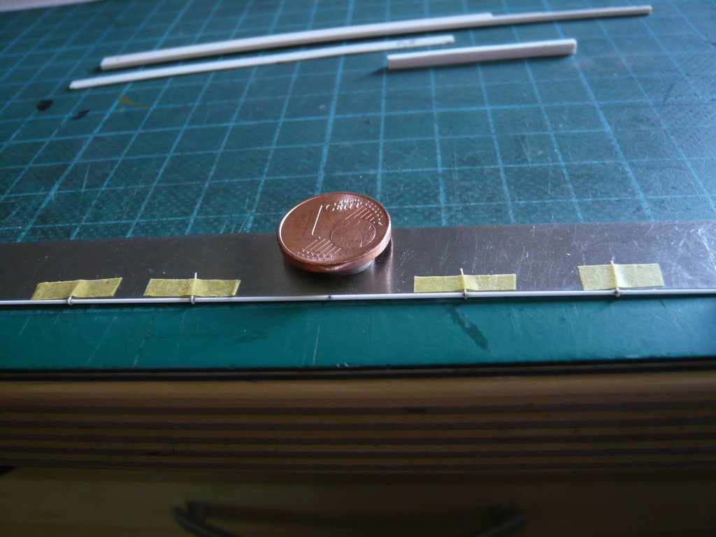
the gluing of the small blocks for cladding the sides of the Door Latches (0,5 mm x 0,5 mm x 1,0 mm) was done on a steel ruler precautionally. First, two short strips (0,5 mm x 0,5 mm) were glued onto the base strip (0,13 mm) with MEK.  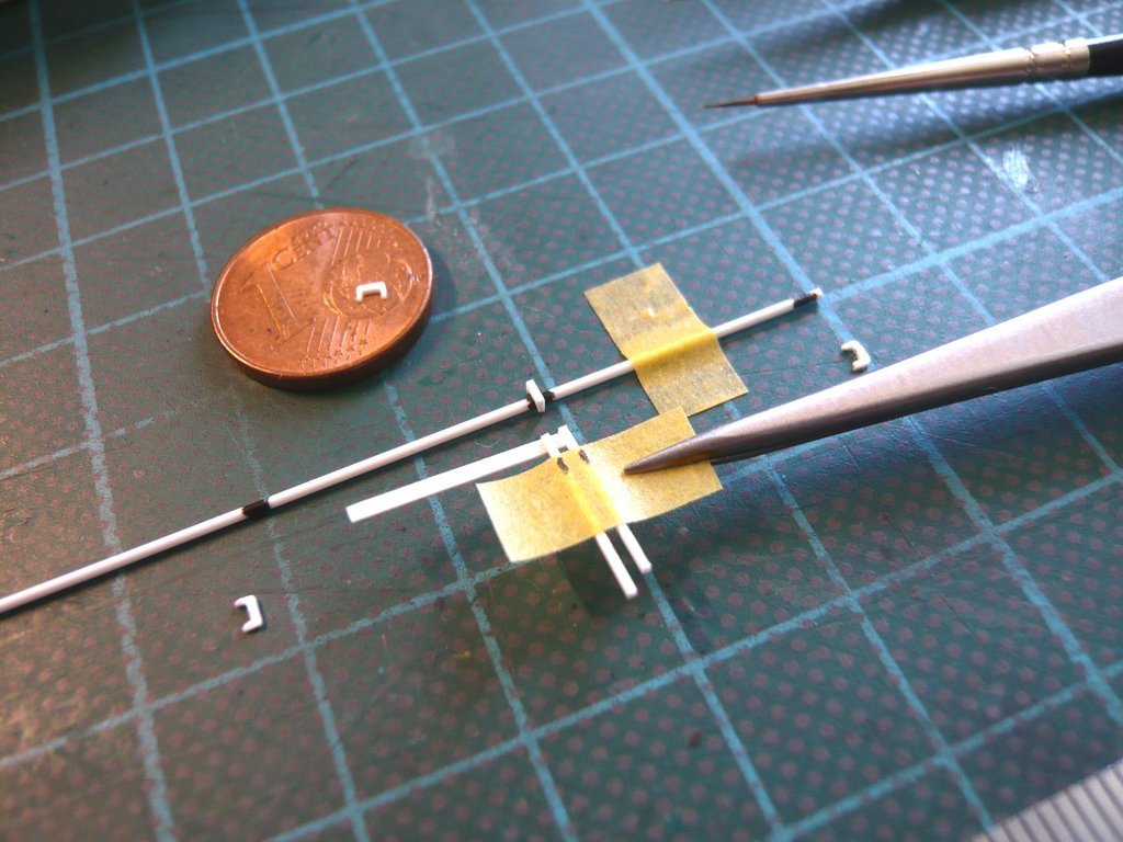 Then the two strips and afterwards also the base strip were cut off, 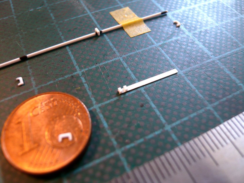 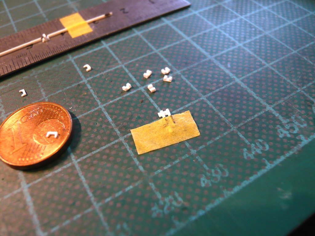 and the seven Latch plates were made in the same way. 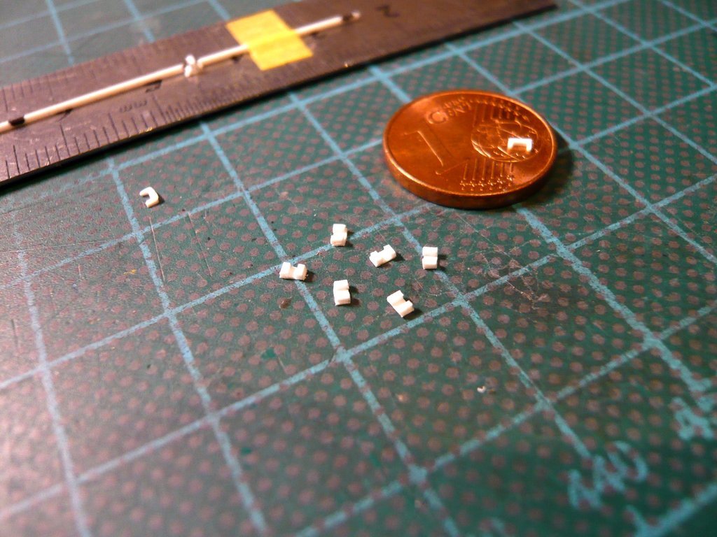 Next followed the gluing of the base plates with the rod, as well as gluing on the Swivel latches.  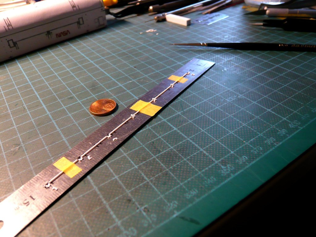 After the Latch strand was completely glued, 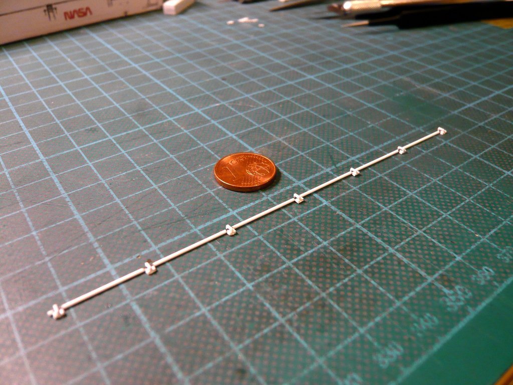 a test fitting on the canister was carried out which was fine so far as. 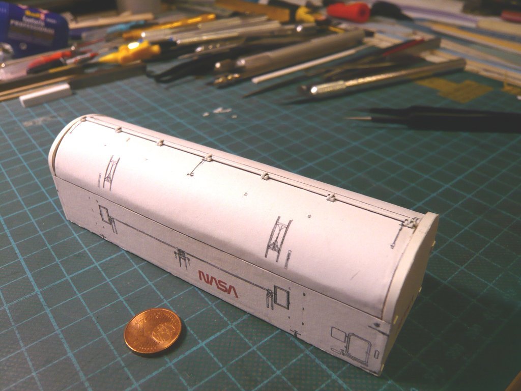 When gluing the Latch strand onto the canister, I was able to use my experience in gluing the SSWS pipe supports to the MLP, when I ascertained at the time that one can also glue plastic with paper by using MEK, which I tried again to be on the safe side, as can be seen here at the glued Styrene snippet.  The general advantage of gluing with MEK is based to its creeping ability, that one can position the part to be glued in place beforehand and that one needs only to brush its outer contour with MEK, what is completely sufficient and was the ideal solution for gluing the Latch strand onto the canister. After I had fixed the strand on the canister with tape strips and aligned it precisely, I first brushed all seven Latch plates with MEK one after the other, and then also the rod sections in between, whereby the MEK evaporates instantly without leaving any residue. 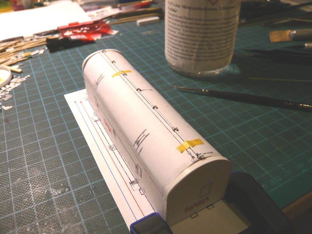 Next I want to scratch the thin tube (Ø 0,5 mm) with the three Door Pull-down Latches,  Source: NASA (STS-132) and glue it onto the Port Side Door, 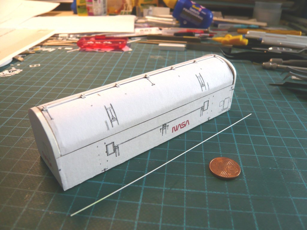 which should be quite tricky because the parts are so tiny and thin.
__________________
Greetings from Germany Manfred Under construction: Launch Pad 39A with Challenger STS-6 (1:144)
|
|
#2686
09-08-2022, 04:35 PM
|
||||
|
||||
|
Hello everybody,
and so now to this thin tube (Ø 0,5 mm) on the Port Side Door with the three tricky Door Pull-down Latches. As one can see, with the diameters the associated parts are getting smaller and thinner too, wherewith I inevitably reach the limits of what is feasible when scratching in my scale (1:160), wherefore I have to lower my sights regarding the attention to detail a little bit. The pipe itself is not a problem with Ø 0,5 mm, but at first glance the four Mounting Clamps with Ø 0,15 mm seem hardly be representable at least of plastic and difficult to assemble, as well as the rod systems of the three Pull-down Latches.  Source: NASA (STS-132) But don't be frightened! Well begun is half done. The following image shows the dimensions of the individual parts determined for scratching, Source: NASA (STS-114) at whose sight I was quite disillusioned, because I immediately realized that I might have to leave out some of the tiny details. First I made the markings for the four clamps on the Evergreen rod (Ø 0,5 mm). 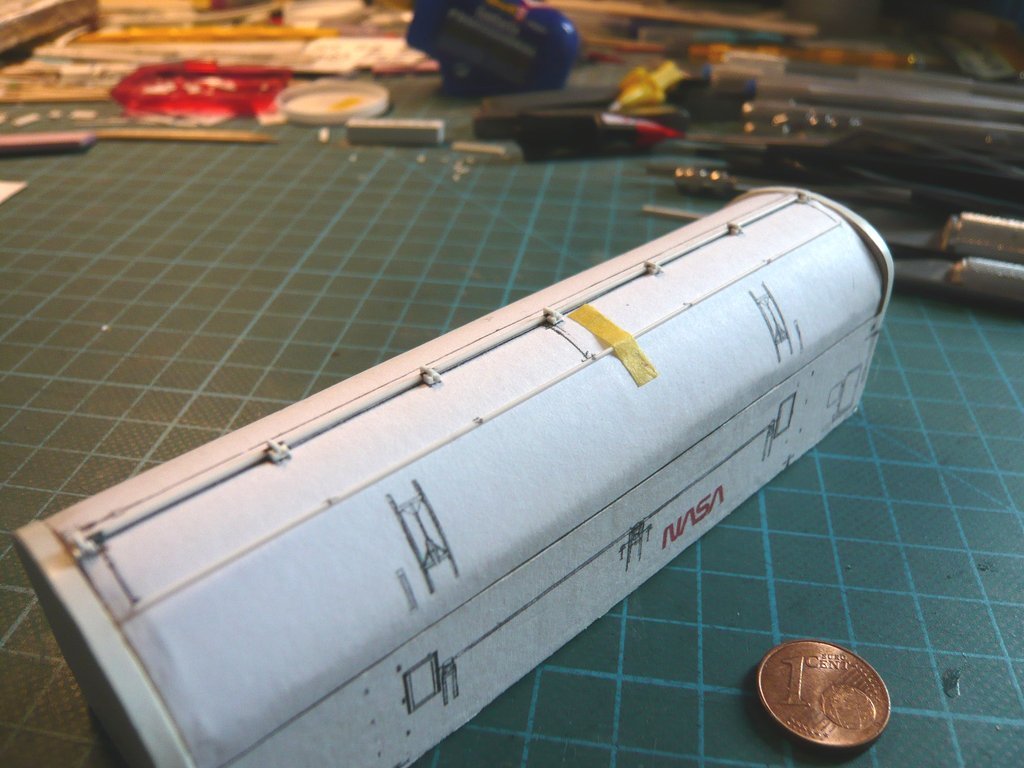 At the same time I've thought about what material I could scratch the clamps (Ø 0,15 mm) out of. However, since such a diameter made of plastic does not exist in hobbyist supplies, I had to come up with something, and have immediately thought of hand broom hairs, which luckily have a similar diameter.However, a first attempt by winding such a hair around a pin quickly proved to be unsuitable, since I would then have to glue tiny curls, which would degenerate into a hopeless disaster and I therefore rejected it. 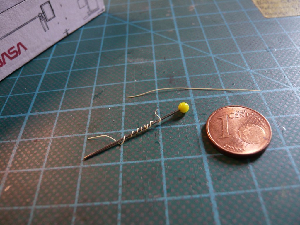 So it would make sense to bend the broom hair around the rod before gluing it, 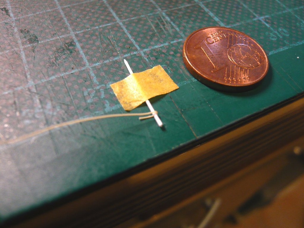 or even better, to stick it to the rod with Pattex Superglue before bending and bend both ends after fixing them beforehand. 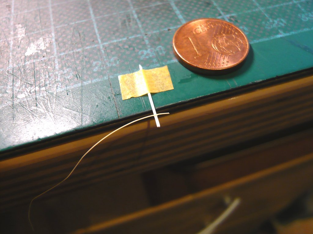 In this state it should be possible to carefully glue the rounded clamp onto the rod with MEK, after which the overhangs could then be trimmed off flush, which worked, as one can see here. 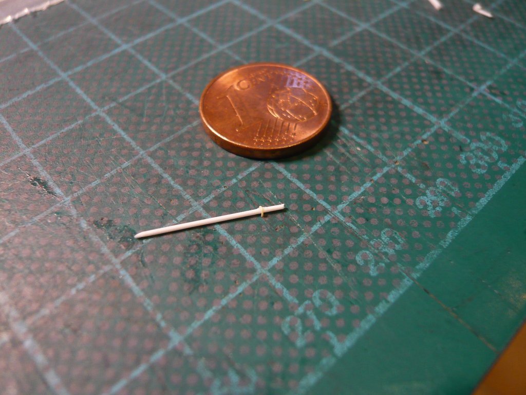 And this is how I proceeded: - Gluing the clamp sections with UHU-CA, 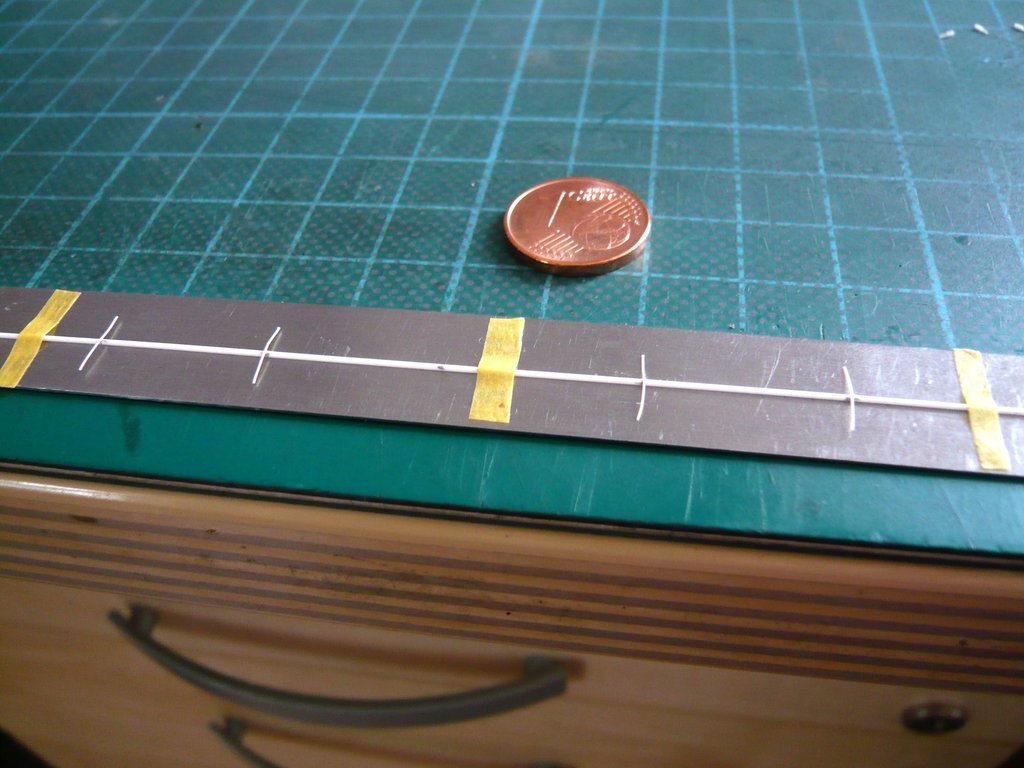 - Turning around of the rod and pinching the overhang under the ruler, as well as bending up the other side of the overhangs and gluing the curves with MEK, 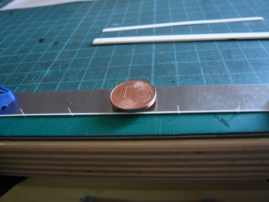 - Bending over of the overhangs and gluing with MEK, 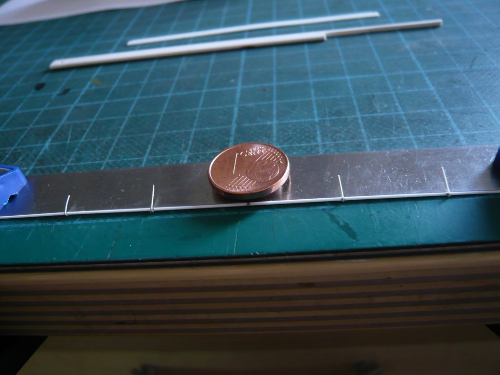
__________________
Greetings from Germany Manfred Under construction: Launch Pad 39A with Challenger STS-6 (1:144) Last edited by spacerunner; 09-08-2022 at 05:22 PM.
|
|
#2687
09-08-2022, 04:36 PM
|
||||
|
||||
|
- Fixing of the overhangs with tape and flush cutting with a razor blade,
  - Removing of the ruler and trimming off the remaining overhangs, wherewith the rod with the four Mounting Clamps was completed. 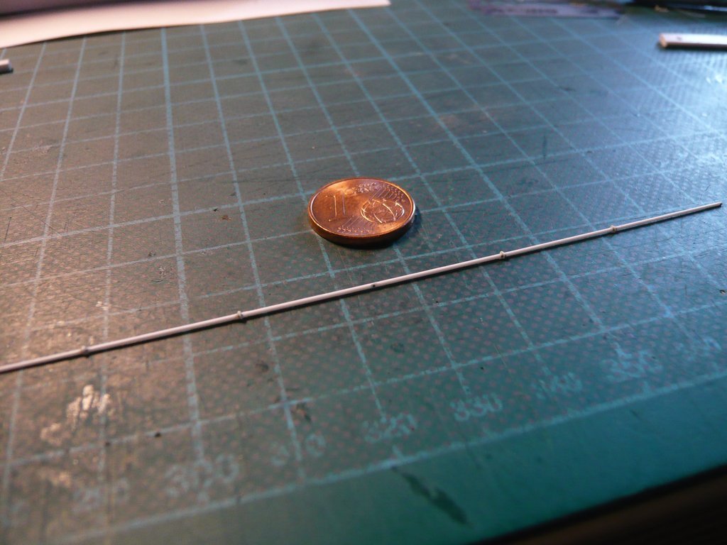 - Fixing of the finished rod with tape onto the Port Side Door and carefully gluing with MEK, 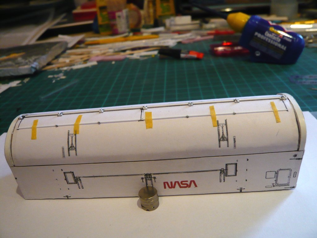 wherewith the first step was done. 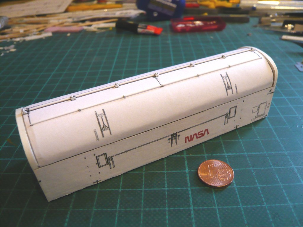 Even if the tiny clamps are barely visible, I know that they are there, and exactly as I imagined.  Now only the Rod systems are missing, which one can see on this image, Source: NASA (STS-132) whereby some of them are so tiny that they have to be simplified a bit.
__________________
Greetings from Germany Manfred Under construction: Launch Pad 39A with Challenger STS-6 (1:144) Last edited by spacerunner; 09-08-2022 at 05:01 PM.
|
|
#2688
09-11-2022, 01:56 AM
|
||||
|
||||
|
Hello everybody,
and thus to the leverage system of the Door Pull-down Latches. Source: NASA (STS-132) The tiny Link joint (0,4 mm x 1 mm) is connected at the rear end with a short Joint rod (Ø 0,3 mm x 0,5 mm), which is sitting in a bracket, and at the front via a Lever arm (0,15 mm x 4 mm) with the long tube of the Port Side Door. Since such short parts can hardly be handled and glued, one has to start with longer parts,  and can only carefully cut them to the final lengths after the glue has dried.  And that is what it looks like, if it is successful.  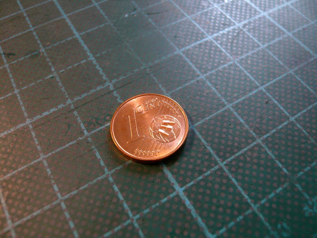 The rear mount of the Joint rod is also articulated mounted, but so tiny that I could only indicate it with greatly simplified parts. 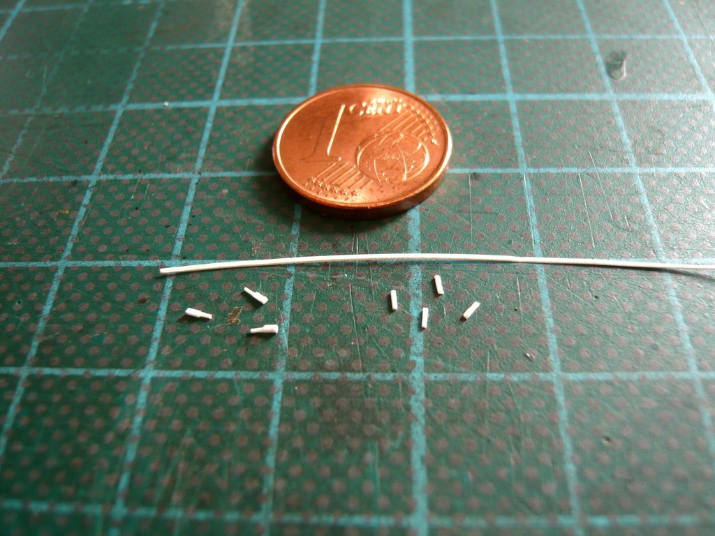 The gluing of these tiny things was done with different glues and was the expected stressful matter,  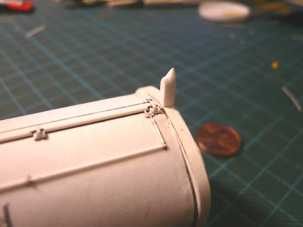 where to my horror one of the three Link joints jumped out of the tweezers and couldn't be found anymore, which is why I had to scratch it once more.   But with that, these three rod systems are done and in place, although they can hardly be seen. 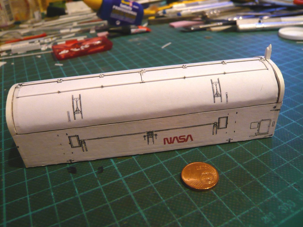 On the opposite Starboard Side Door there is still this small Leverage,  Source: NASA (STS-135) which is connected to the end of the Torque Tube,  Source: NASA (STS-124) what I would like to try at least.
__________________
Greetings from Germany Manfred Under construction: Launch Pad 39A with Challenger STS-6 (1:144)
|
|
#2689
09-17-2022, 05:05 PM
|
||||
|
||||
|
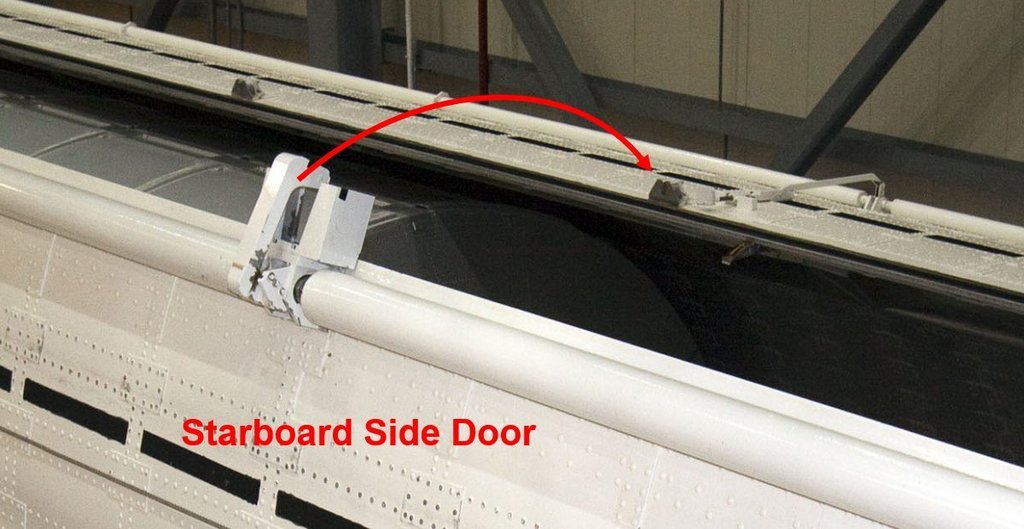
Hello everybody,
while I was looking at this image, I noticed this long steel cable to the right of the Torque tube, which is attached by a hinge to a strut and runs across the entire Starboard Side Door,  Source: NASA (STS-135) where it is locked in a bracket. Source: NASA (STS-135) At first I couldn't explain the meaning and purpose of this steel cable, but I want to try to find out somehow. Maybe someone of you knows wherefore it is good for ... And then it was down to business, because these linkage is really tiny.  For the left part of the linkage, which is connected to the end of the Torque tube, I cut narrow strips of Styrene (0,13 mm), 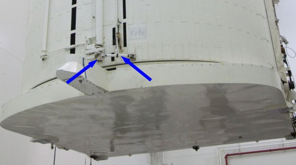 which I glued onto both sides of a rod (Ø 0,25 mm x 2,5 mm) to this small fork as the right part, which then were reduced to approx. 1,5 mm which was quite stressful to handle. This tiny part was so light that it stayed stuck to the tweezers for the photo.  The joint of the strut attached to the rod I indicated with a tiny eyelet made of Lead wire (Ø 0,3 mm), which I 'rolled flat' by twisting back and forth under a steel ruler to Ø 0,2 mm, wherefore some preliminary tests were required. 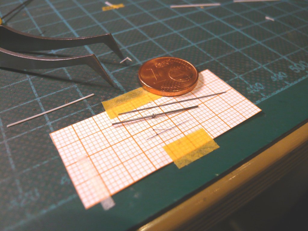 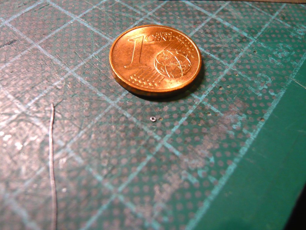 The final eyelet then looked like this, 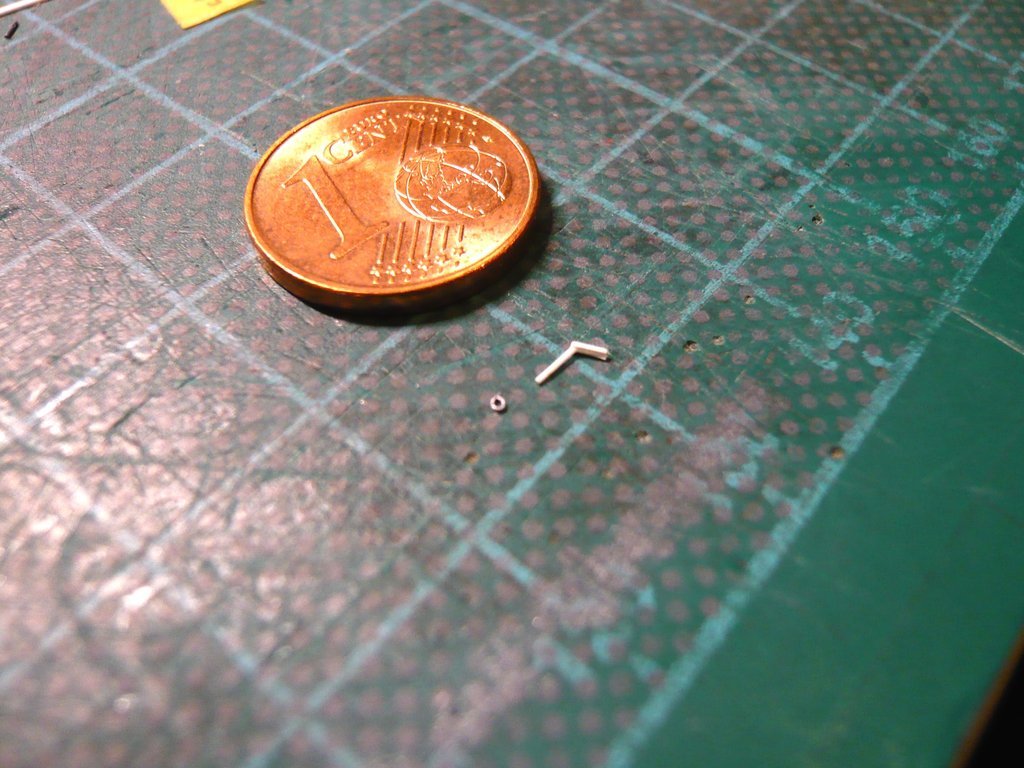 which I threaded and glued onto the rod in a rather hairy action.  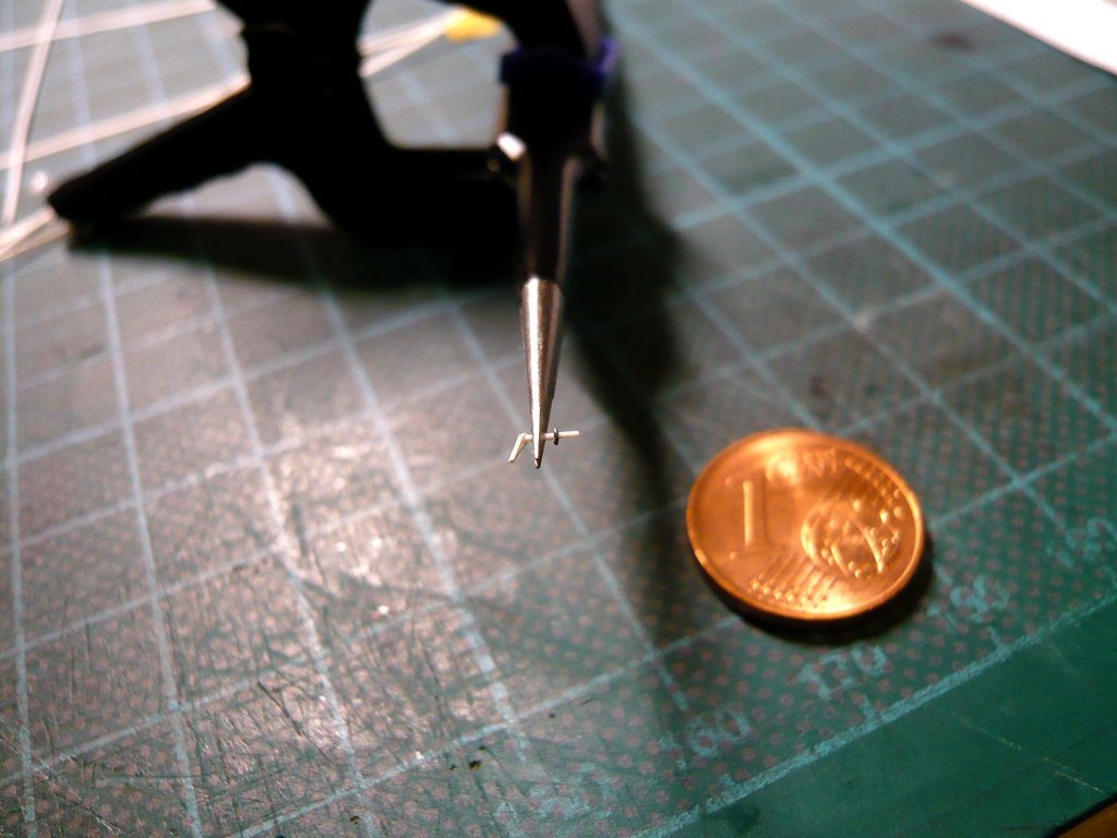 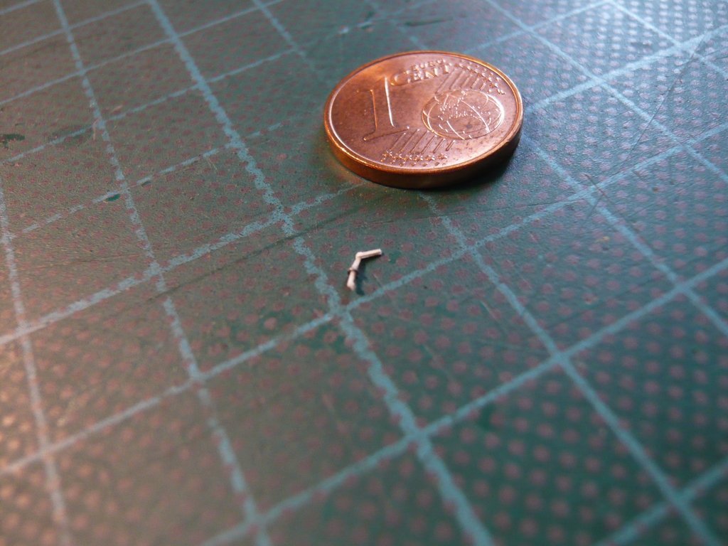 Then I carefully glued the linkage onto the door with CA/MEK, 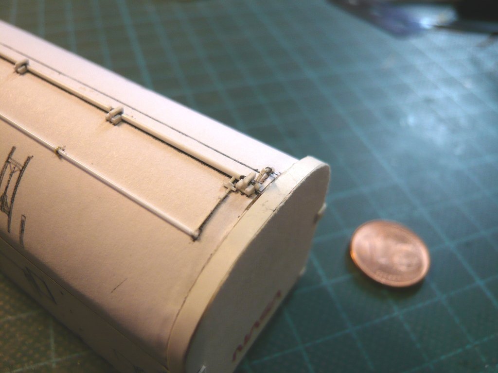 and let everything dry. 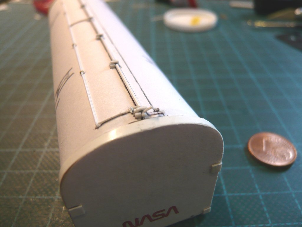 Next comes the lateral strut, which reaches from the rod joint (eyelet) to the attachment point of the steel cable.
__________________
Greetings from Germany Manfred Under construction: Launch Pad 39A with Challenger STS-6 (1:144)
|
|
#2690
09-18-2022, 04:37 PM
|
||||
|
||||
|
Hello friends,
meanwhile I found out what this steel rope was all about, which sometimes sagged down a bit, like in this image.  Source: NASA (STS-101) And if I'm interested in a technical detail like that, then, as is well known, I get to the bottom of it. And through my Swedish friend David from NSF (DaveS) I met a member of the then Can Crew whose explanation is as amazing as it is simple. "That cable what we tied off to for fall protection when we walked down the door in the horizontal configuration to verify the latchs were closed properly prior to ratcheting into the closed position." After all, the Transporter with the Canister had a height of approx. 28 ft, and from there one shouldn't necessarily be able to fall off it.
__________________
Greetings from Germany Manfred Under construction: Launch Pad 39A with Challenger STS-6 (1:144)
|
 |
|
|


 Linear Mode

