


|
|
|
#2691
 10-11-2022, 06:09 PM
|
||||
|
||||
|
Hello everybody,
I'm still dancing around on the Payload Bay Doors without a Safety rope,  what needs to change immediately. But these mini-struts took me some lot of effort, which is why I finally wanted to get this over with. what needs to change immediately. But these mini-struts took me some lot of effort, which is why I finally wanted to get this over with. From this perspective als well as at high resolution, one can still see the details best.  Source: NASA (STS-114) On the one hand there is the lateral strut already discussed next to the rope holder, which I tried my hand at first and even managed the small [color =blue]wire[/color] to be inserted between the rope holder and the turnbuckle, made of a tiny lead wire (Ø 0,2 mm x 0,5 mm), but please don't ask me how ...  The result is already invisible to the naked eye, but I know, as always, that it's there ... The result is already invisible to the naked eye, but I know, as always, that it's there ...  Now only the rope sling is missing, to which the rope will later be attached. 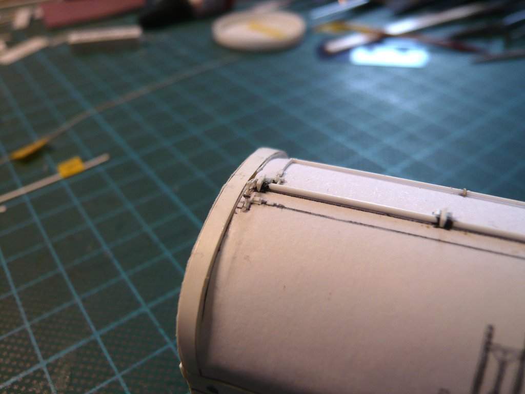 And here this strut made of Styrene (0,13 mm) is now mounted, which one can just barely make out. 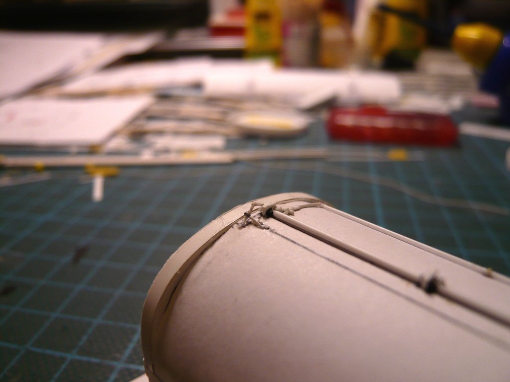 The thin wires ordered for this have also arrived in the meantime. The upper roll is the steel wire (Ø 0,1mm) shipped from China, and below are two NiCr wires (Ø 0,1mm/0,2mm) - Made in Germany. 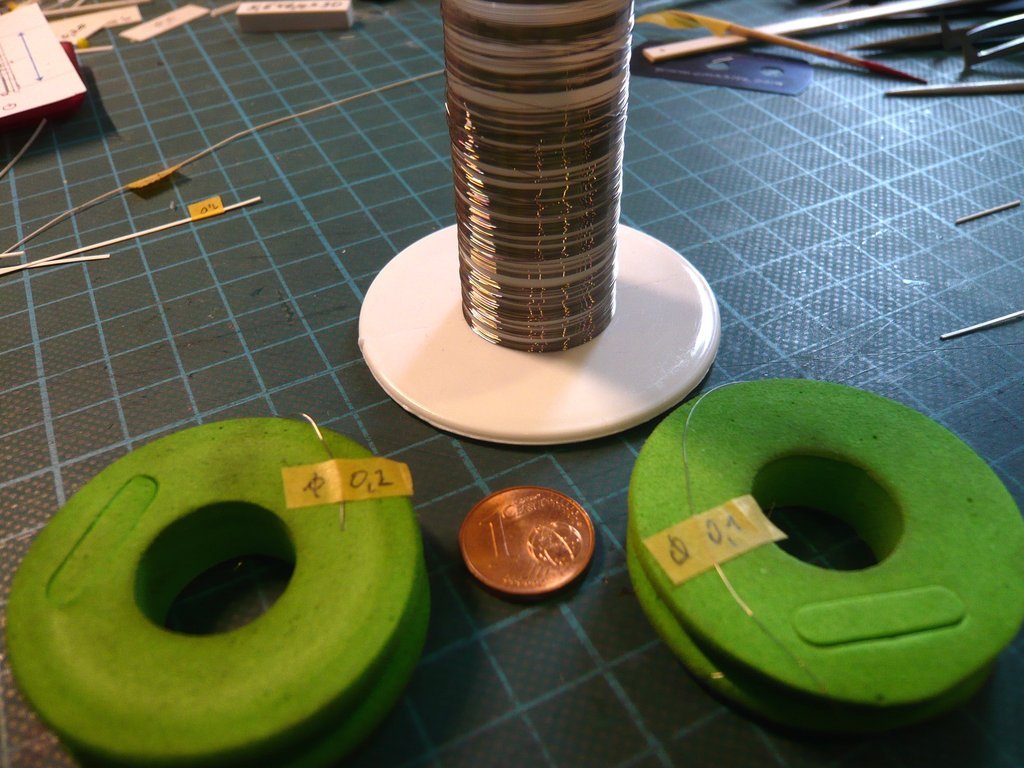 I proceeded in the same way for the rope holder and the turnbuckle on the other side. This time I glued a short NiCr wire (Ø 0,2 mm) between the two Styrene strips of the holder. The overhangs of the parts that are needed for handling are important. 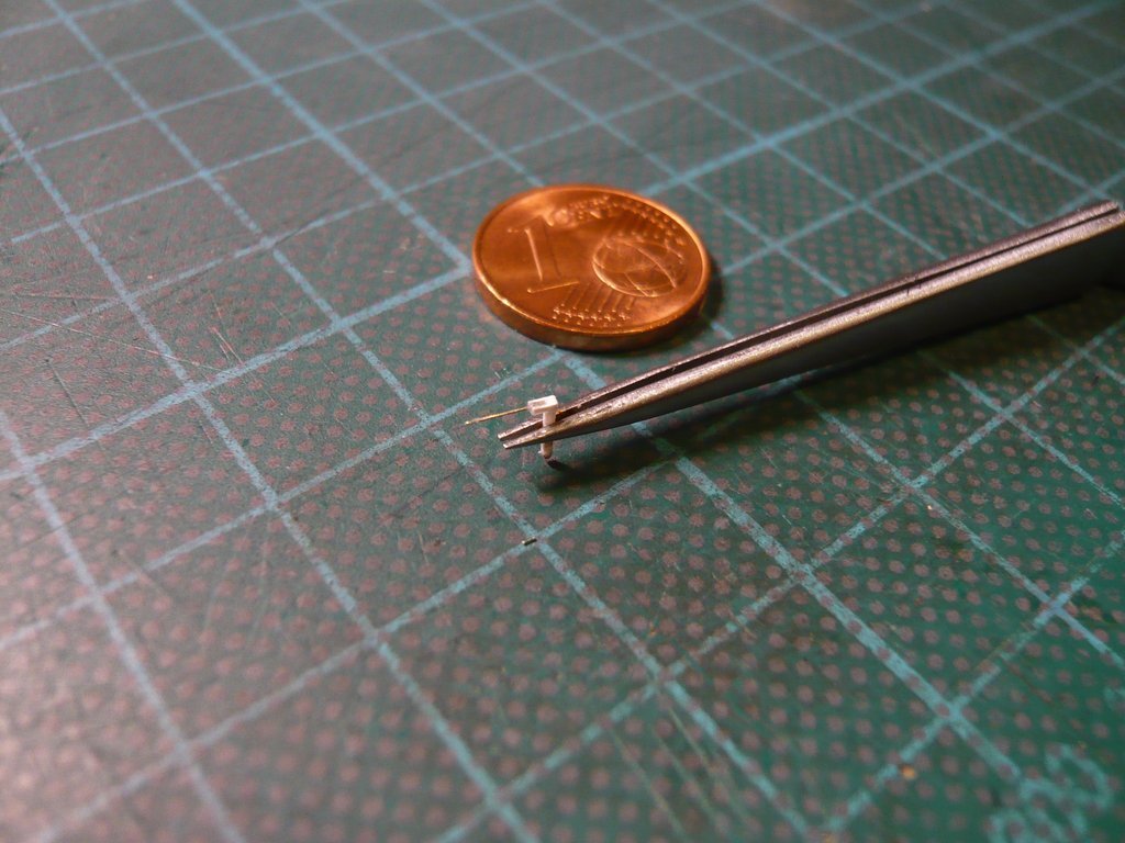  For the turnbuckle I prepared a Styrene rod (0,4 mm x 0,4 mm), using an Evergreen strip (0,5 mm x 0,5 mm). 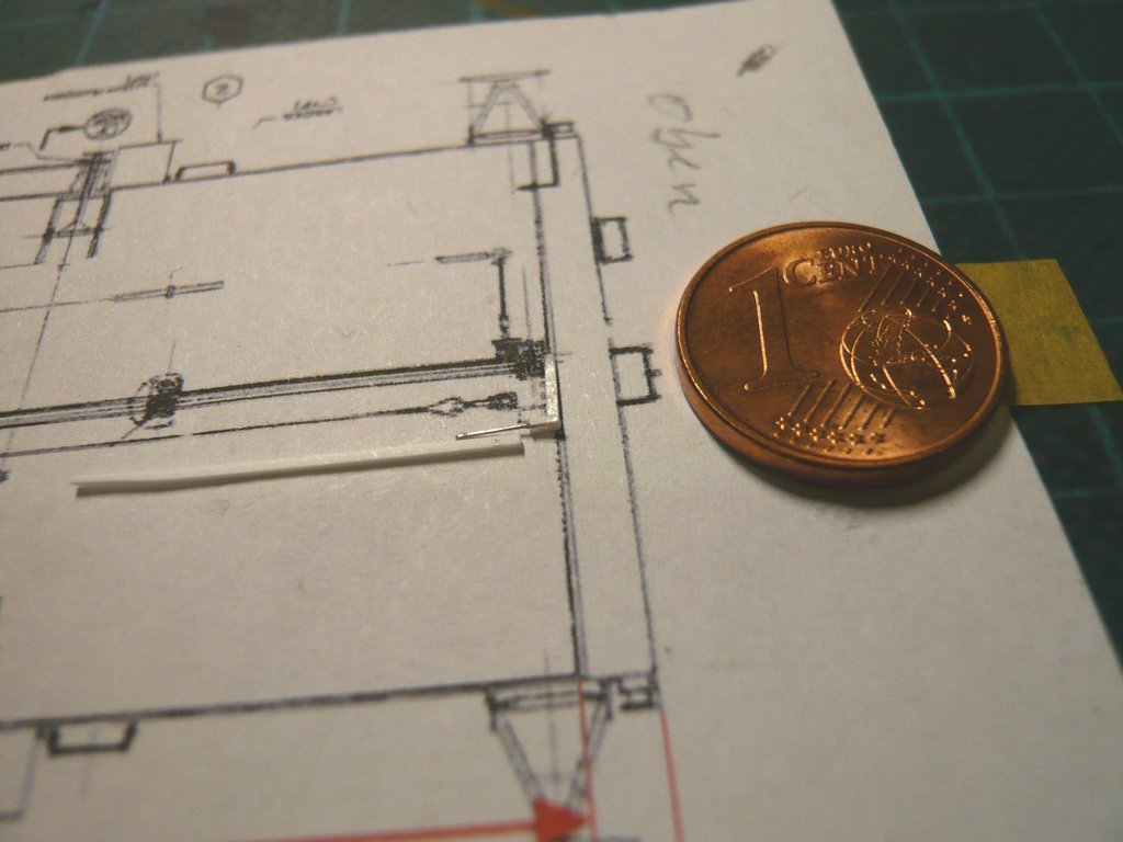 The shortening of the connecting wire between the bracket and turnbuckle to approx. 0,8 mm was a delicate procedure, for which backup tapes were helpful so that nothing could fly away. 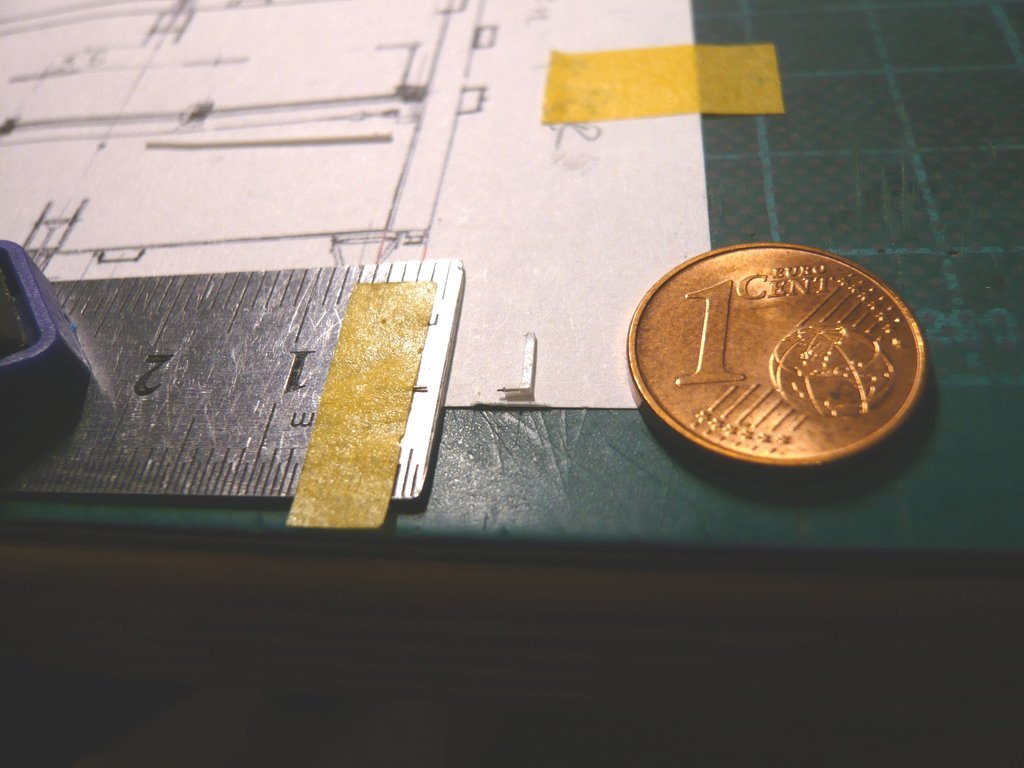 Bending the loop of rope from NiCr (Ø 0,2 mm) into a small eyelet was a stressful fiddling too,  but finally worked after a few tries, but finally worked after a few tries,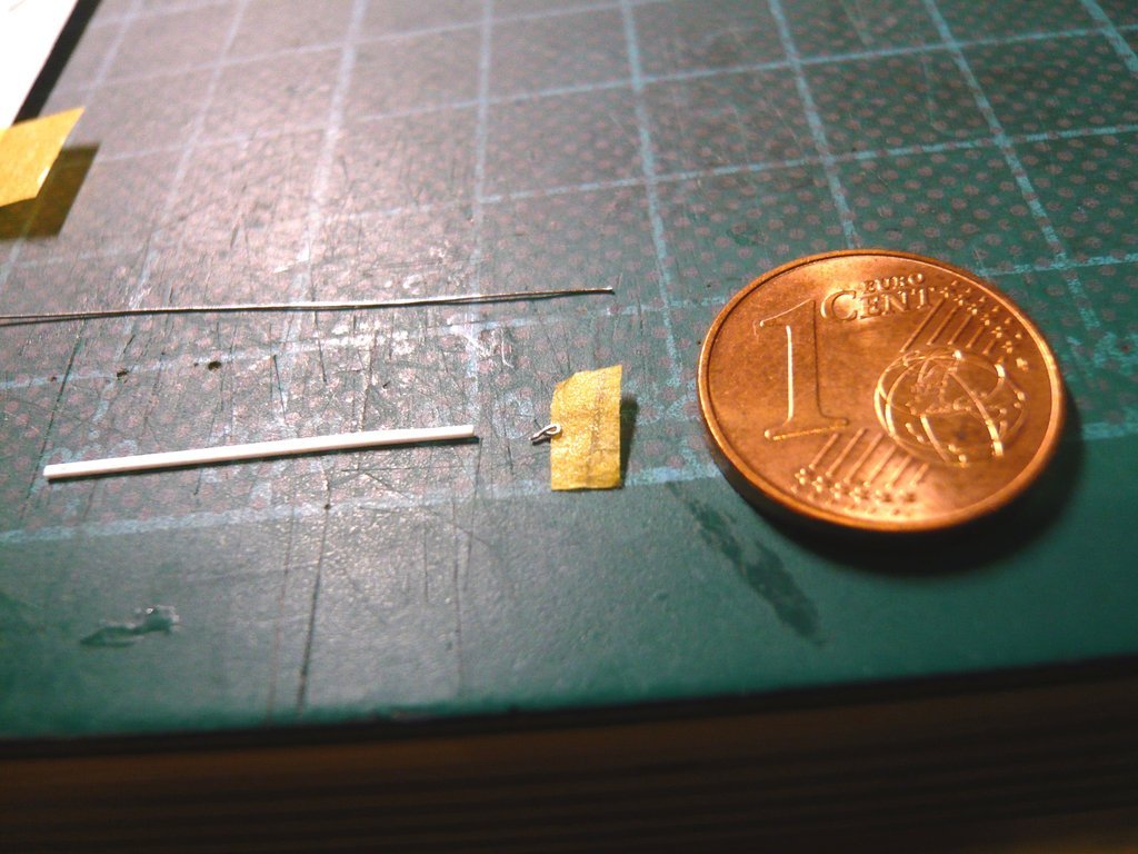 as well as the gluing on the turnbuckle. 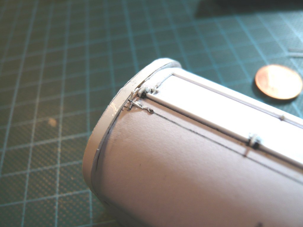 And then the same procedure again on the other side. 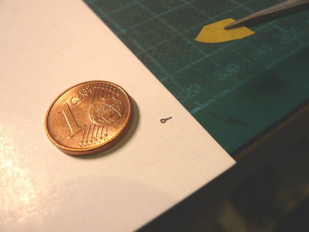 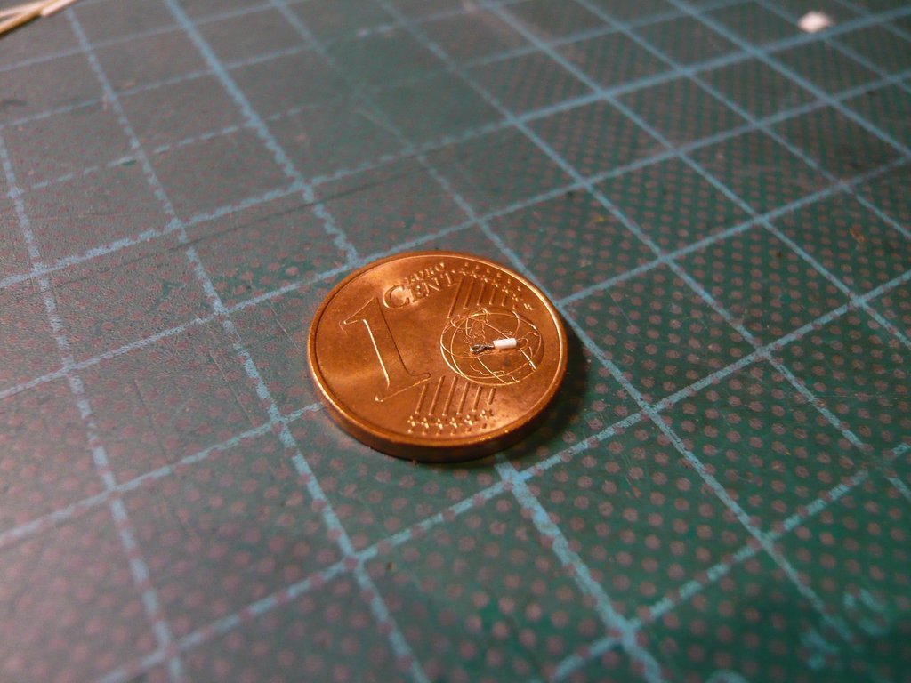 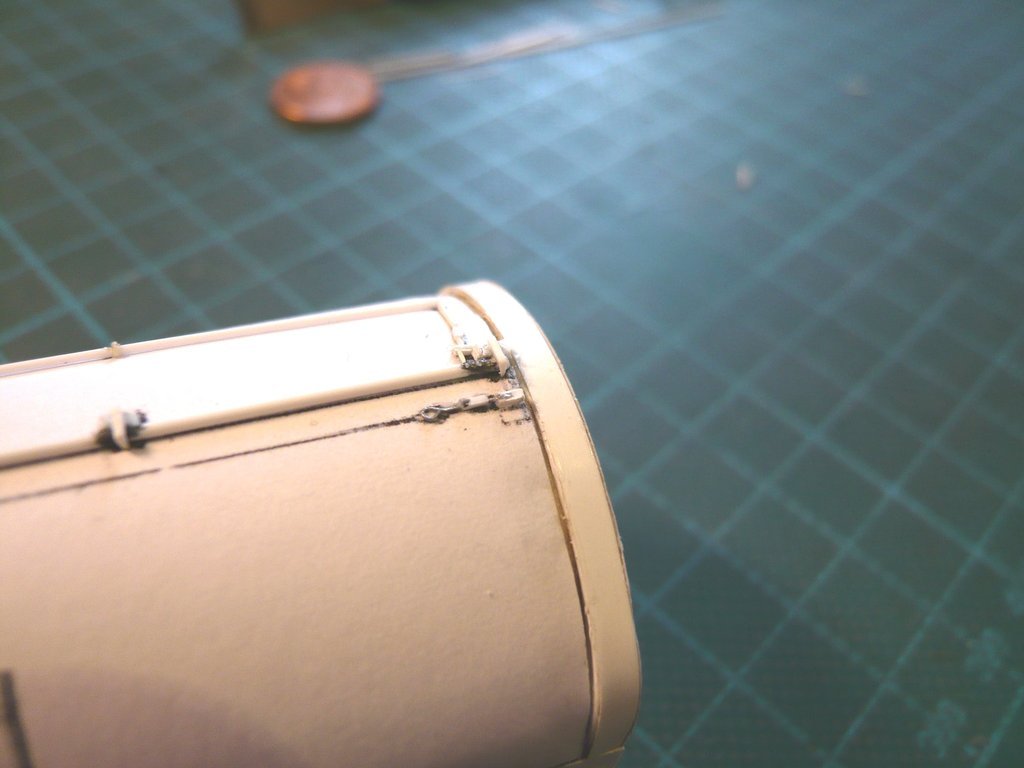 The rope is only glued in later so that it is not damaged when assembling the small parts that are still missing.  
__________________
Greetings from Germany Manfred Under construction: Launch Pad 39A with Challenger STS-6 (1:144) 
|
|
#2692
10-11-2022, 06:13 PM
|
||||
|
||||
|
Hello everybody,
here the Safety rope made of NiCr wire (Ø 0,2 mm) has been put on at least as a test.  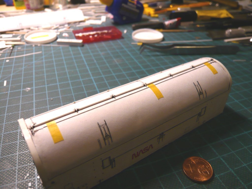 With gluing the cable onto the door, I will wait until the upper linkages of the Door Actuators are glued onto both doors,  Source: NASA (STS-132)  Source: NASA (STS-125) which I have now planned, but for which I first had to determine various dimensions again. Source: NASA (STS-125) In the closed state of the doors these linkages are folded and are only folded out to support the opened doors, as can be seen in this image.  Source: NASA (STS-101) As one can see from the small dimensions, it's again about tiny parts, whereby the two outer sickle-shaped holders seem particularly tricky, whose shape I first drew in order to create a corresponding template for scratching.  As one can see in this image, these holders are extremely narrow at < 1 mm and also very thin (0,13 mm), which are probably difficult to handle. On the upper Evergreen Styrene Strip (0,13 mm) the contour is pre-drawn and the lower bow has already been cut out, which was still reasonably easy to do. 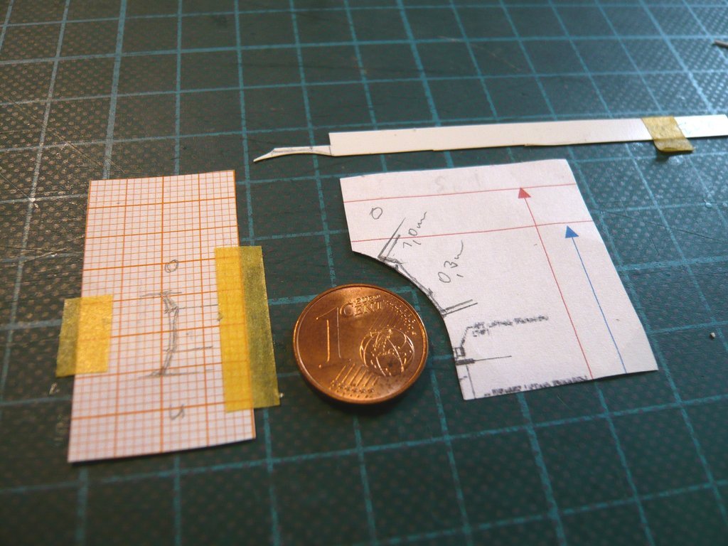 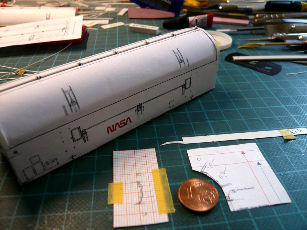 Cutting out the upper contour, on the other hand, will become a stressful affair,  because one can hardly hold tight this narrow sickle in the tweezers. because one can hardly hold tight this narrow sickle in the tweezers. 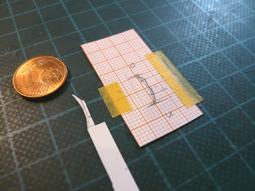 For gluing the linkages between the lateral holders I thought about a Balsa jig,  the top of which I filed to match this lower contour. the top of which I filed to match this lower contour.  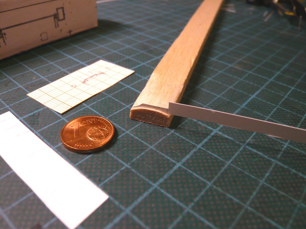 It doesn't matter how, but first I need a total of 8 such holders for both doors. That's why I transferred the lower contour 8 x to a Styrene strip, 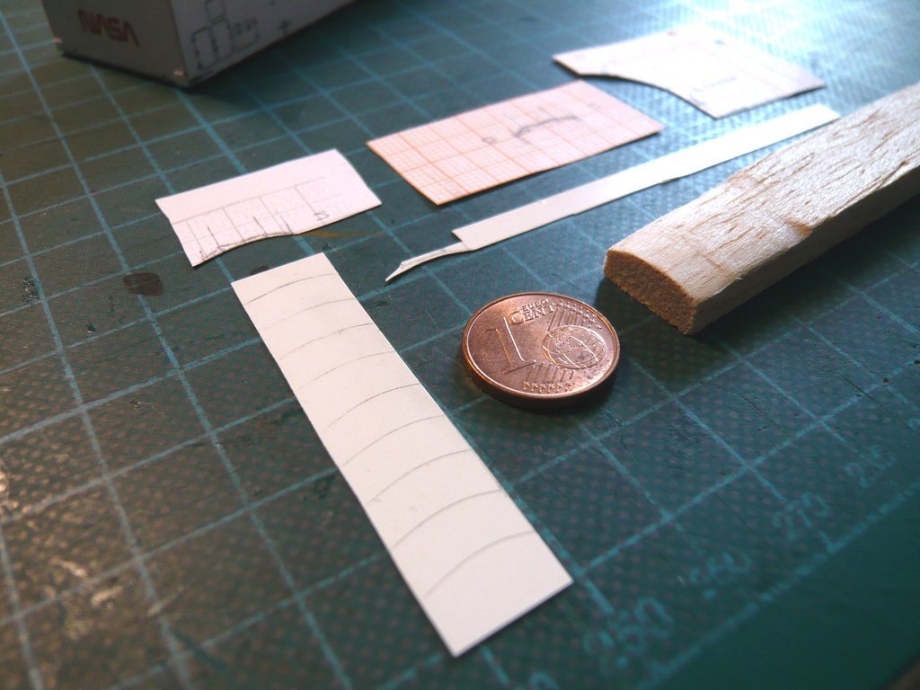 and carefully cut out with nail scissors. And I now have to transfer the upper contour to these parts and cut them out, file them out, or whatever ...  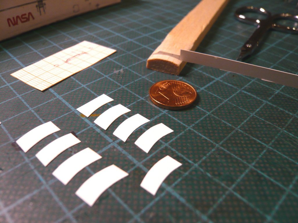
__________________
Greetings from Germany Manfred Under construction: Launch Pad 39A with Challenger STS-6 (1:144)
|
|
#2693
10-11-2022, 06:16 PM
|
||||
|
||||
|
Maybe it will be advisable, to glue the sickles to a bulged Styrene strip,
 then glue in the linkage parts and then glue the holders made in this way onto the doors.  It may all still sound pretty bold and adventurous, but somehow I'll be succeeding already ...
__________________
Greetings from Germany Manfred Under construction: Launch Pad 39A with Challenger STS-6 (1:144)
|
|
#2694
10-11-2022, 06:39 PM
|
||||
|
||||
|
Hello Manfred,
You have devoted your efforts to this project for more than 9 years. Your dedication and perseverance are remarkable. Sehr gut gemacht. p.s. Perhaps, if possible, you can present an image showing all the assemblies that have been completed so far.
|
|
#2695
10-13-2022, 05:32 PM
|
||||
|
||||
|
Thanks Michael for your nice compliment and your interest.
 The time for a visual inventory has not yet come, but the things are well stowed away in the closet.
__________________
Greetings from Germany Manfred Under construction: Launch Pad 39A with Challenger STS-6 (1:144)
|
|
#2696
10-13-2022, 05:40 PM
|
||||
|
||||
|
Hello friends,
after carefully cutting out the holder, I held it in tweezers and carefully smoothened it for a while at the top side with my finest TAMIYA diamond file for photo-etched parts, measured its height again and again and compared the contours with the STS-132 -Photo,  Source: amazon.de until I was halfway satisfied with this prototype, which differs pleasantly from my first guinea pig (above). 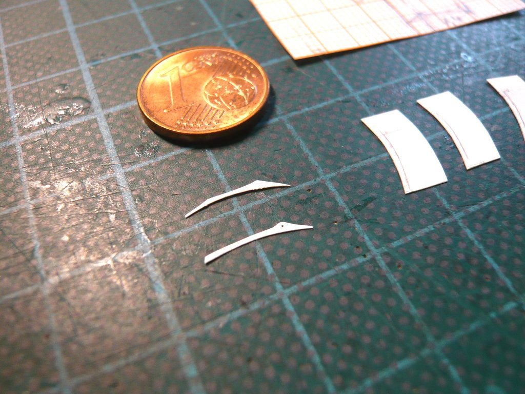 In order to make my work easier when making the remaining 7 holders, I've bored a small hole (Ø 0,3 mm) at the location of the upper leverage axis, which I can now transfer to the rest of the holders and then pre-drill, which will hopefully make marking the upper contour easier. So far for the theory, let's see if it works like that.
__________________
Greetings from Germany Manfred Under construction: Launch Pad 39A with Challenger STS-6 (1:144)
|
|
#2697
10-15-2022, 04:50 AM
|
||||
|
||||
|
Hello everybody,
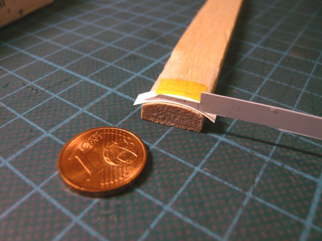
since the one-off production in this way is a bit too tricky and time consuming and the shape of the parts is also not very reproducible,  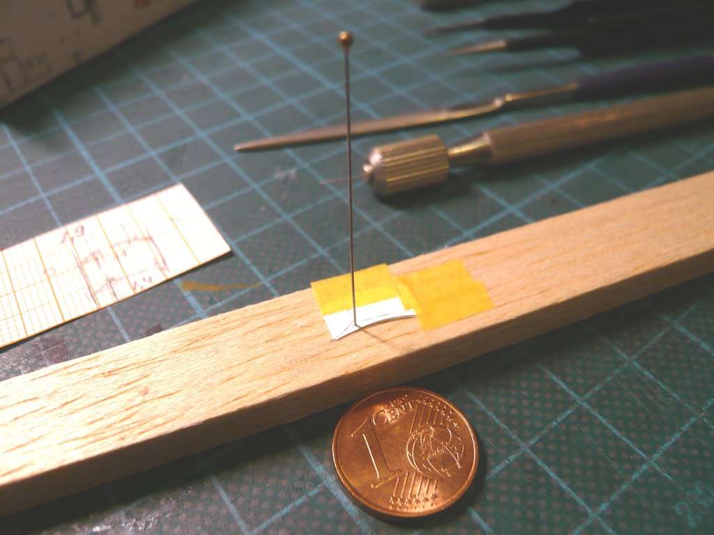 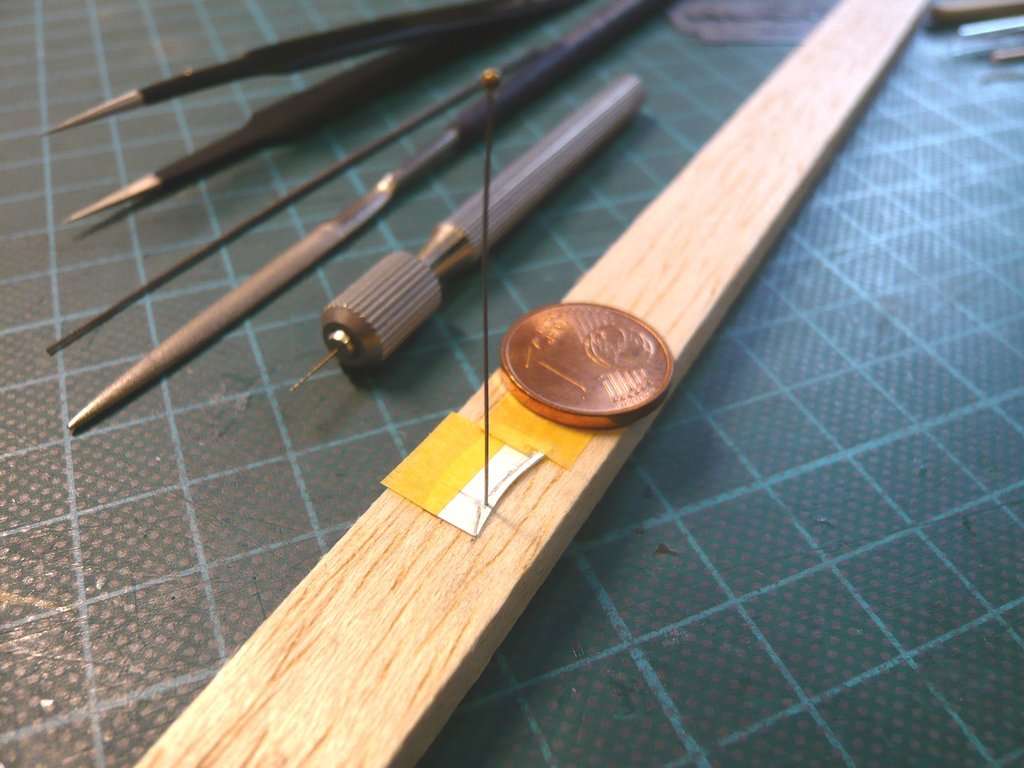 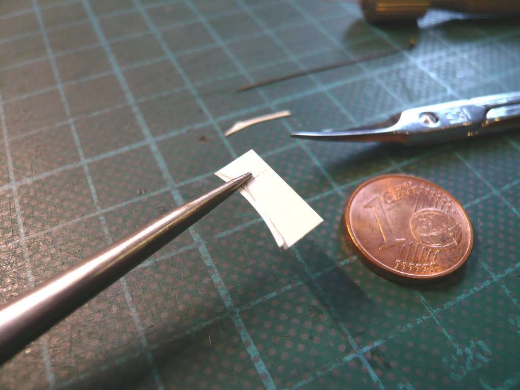 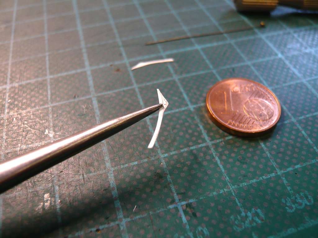 I switched to a kind of small series production. To do this, I drilled through a strip at the linkage axis (Ø 0,3 mm) and then this strip with 7 other strips, with the lower contour cut out, as well superimposed as possible and clamped in scissor tweezers.Then I carefully drilled through the entire bundle and pushed a steel wire (Ø 0,3 mm) through the hole, whereby the bundle is at least fixed to the rod axis. Then I smoothed the bundle a bit on the underside and on both ends to compensate for small differences and to set a uniform length of 11 mm. 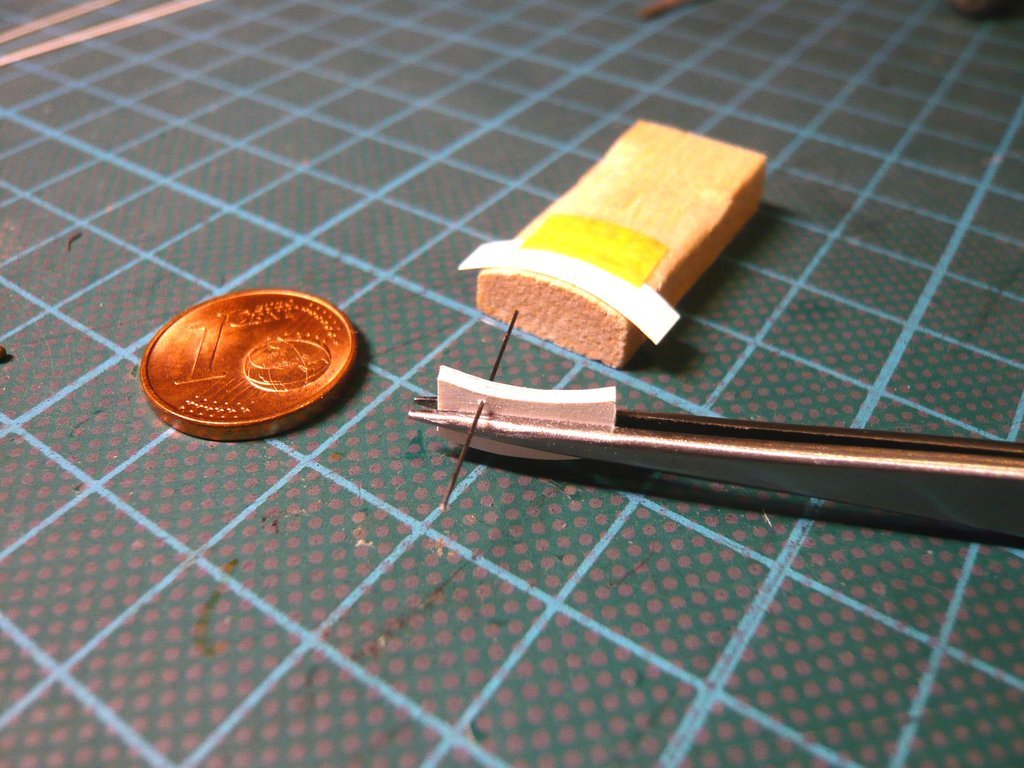 And as one can see on this image, the bundle fits well to the curve of the Balsa jig and hopefully also later on the canister doors. 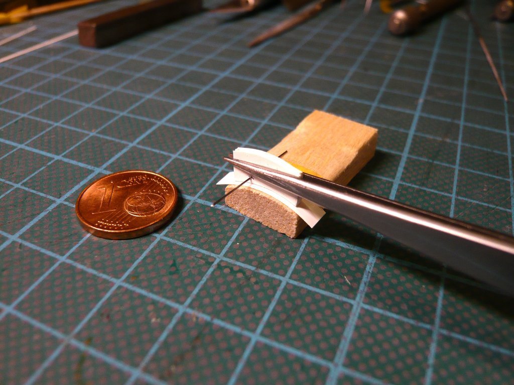 Now I can take the bundle apart again and trace the upper contours individually, whereby the position of the stripes is fixed by the wire. Then the upper contours are cut out one by one as close as possible, and put the bundle back together. Then I'll try to smoothen this narrow bundle to an even shape at the top and hope I can do that.
__________________
Greetings from Germany Manfred Under construction: Launch Pad 39A with Challenger STS-6 (1:144)
|
|
#2698
10-18-2022, 05:05 AM
|
||||
|
||||
|
Hello everybody,
and I proceeded in exactly the same way and drew the upper contours of the individual sickles one after the other using my original form on the remaining 7 Styrene Sheets (0,13 mm), 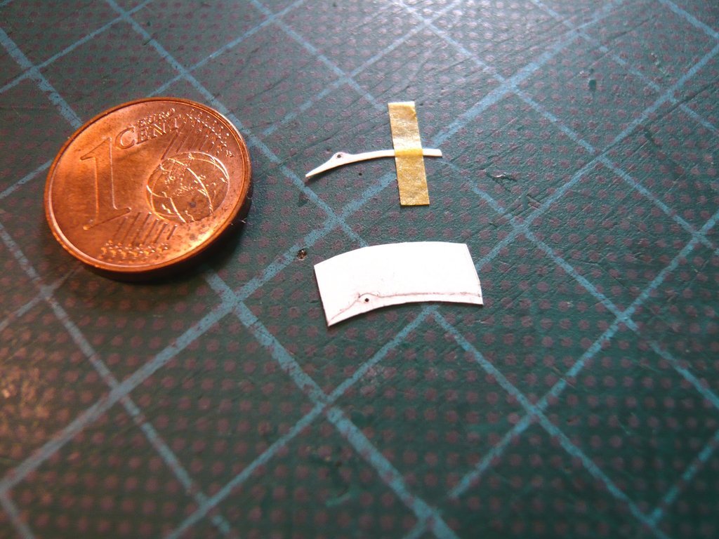 whereby the original form always has been fixed by the steel wire (Ø 0,3 mm) and by a tape strip on a Balsa plate. 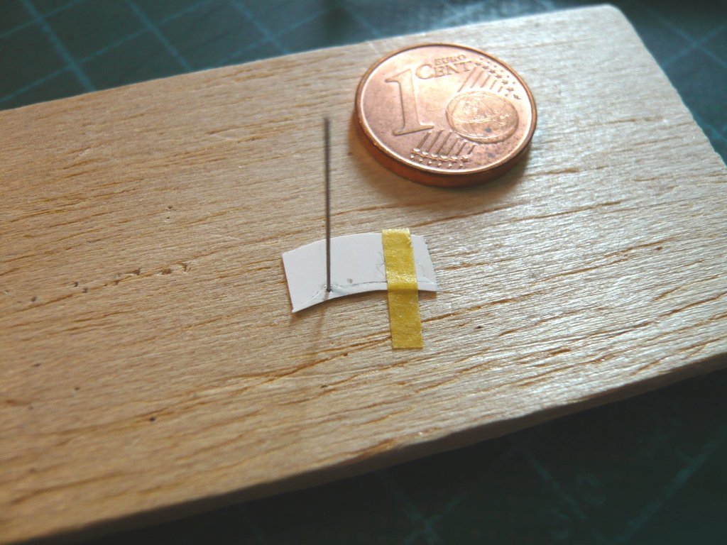 Then I've carefully cut out the top sides of the sickles with the nail scissors as close to the contour as possible, which was a very tedious and stressful affair, since the part had to be re-clamped several times in the scissor tweezers, which meant that the strip that was accessible became narrower and narrower.  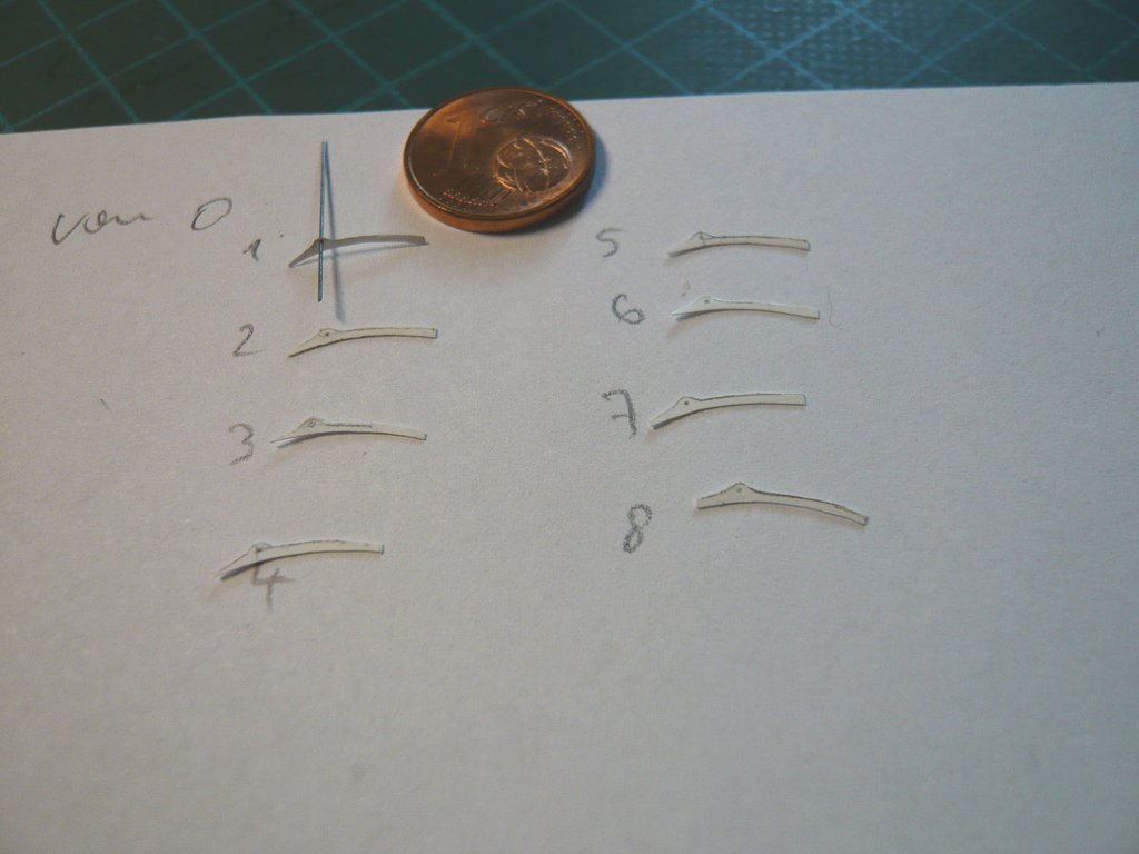 Then I threaded all the sickles on the wire in reverse order, whereby my original form (1) came to lay at the front position. 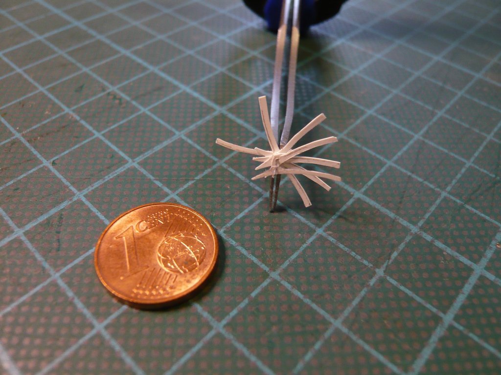 All my subsequent attempts to evenly trim this aligned, narrow bundle on the top were ultimately unsuccessful, despite all efforts to clamp and fix it somehow, which is why I unfortunately had to give up this approach. 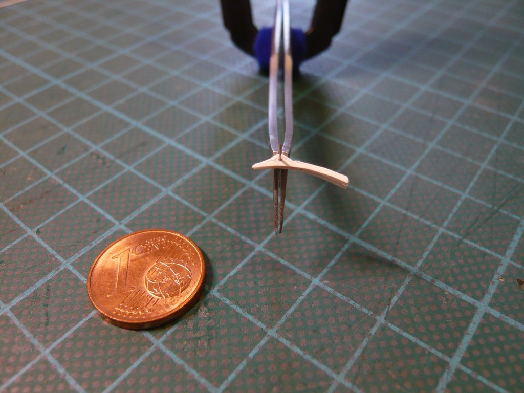 Instead, I started by smoothing each of the 7 sickles individually at the top side to the shape of the original form in front of me,  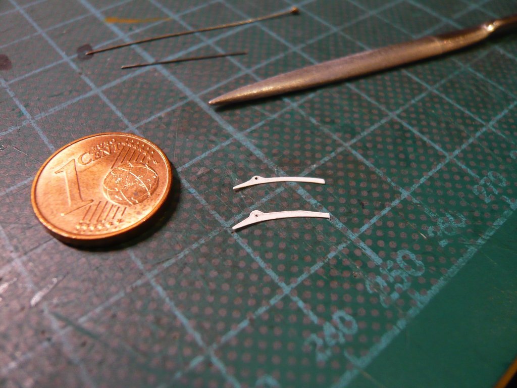 for what I held them in different positions in the tweezers and worked the upper contour with different files for so long, 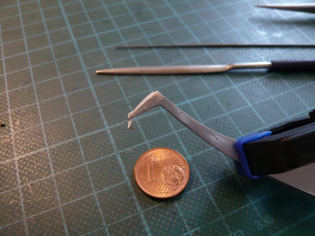 until I was reasonably satisfied with their shape and almost a twin had been formed. 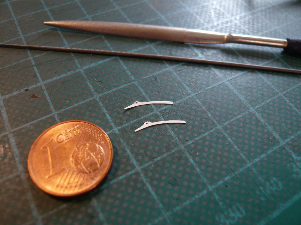 I then put the first pair of twins on a Styrene rod (Ø 0,3 mm) as a rod axis, 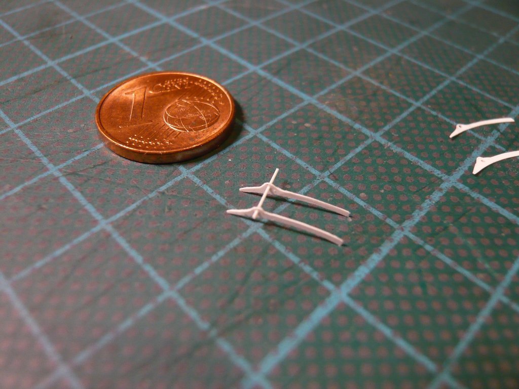 and immediately tried a test fitting on the canister, which looked quite promising, 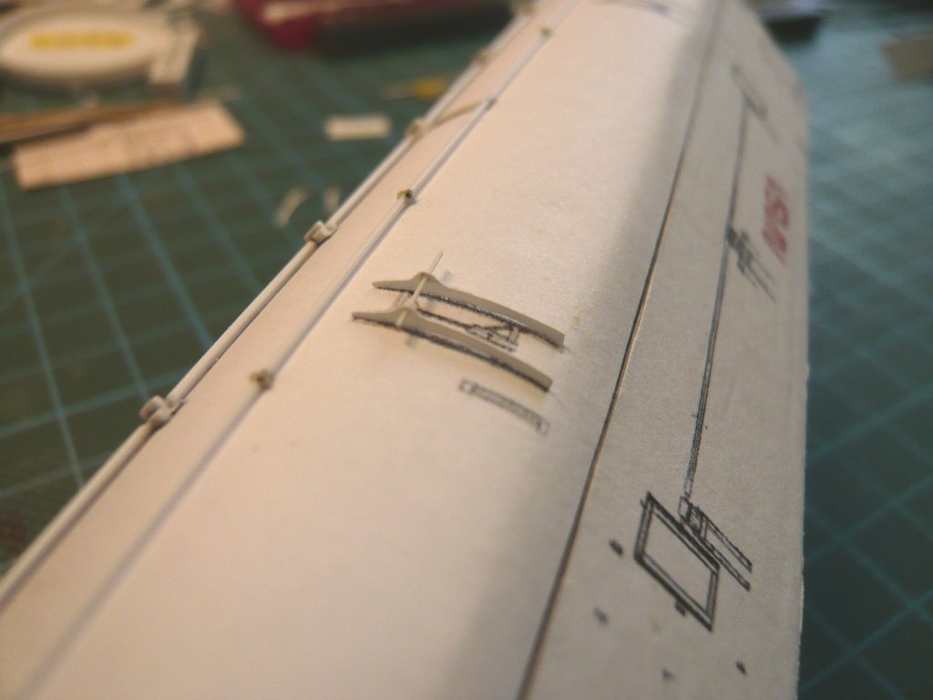 which gives me courage to work on the remaining sickles in the same way, so that I end up with 4 pairs of twins for the Door Actuators on the doors.  So far for today.
__________________
Greetings from Germany Manfred Under construction: Launch Pad 39A with Challenger STS-6 (1:144)
|
|
#2699
10-23-2022, 05:20 PM
|
||||
|
||||
|
Hello everybody,
before I turn towards the remaining sickles, I took a closer look at the linkages of the upper Door Actuators and thought about how and from what I could best scratch these filigree individual parts, whereby it is always important for me to understand the interaction of the components of an assembly and their function to some extent. And for this it is always worth looking at detailed photos with high resolution from different perspectives, like this one here of the upper linkage in the folded state, which I want to reproduce,  Source: NASA (STS-132) as well as here in the unfolded state, in which one can see some details on the two rotary axes more clearly. After a close look at the linkage, its lower part seems to be a coherent strut construction, which I have marked in blue,  Source: NASA (STS-135) which this photo in the zoom also seems to confirm. The longer support strut lies on top of it, which is rotatably mounted at the upper end between the side parts. Source: NASA (STS-132) Before opening the doors, both linkages of the door drives are folded out and screwed together, thus forming their upper supports, which are taken up by the drives on the canister walls on which the opened doors rest. For replicating the individual parts this photo of the STS-125 is ideal suitable, on which I determined the dimensions of the most important parts and immediately searched for suitable material in my inventory. Source: NASA (STS-125) I started with the lower rotary axis, for which I used an Evergreen strip (0,5 mm x 0,5 mm), on which the four struts are attached, which are probably welded together to a kind of a fork. Then I glued the upper rotary axis on one side with MEK, adjusted the distance between the two sickles with a suitable spacer (3 mm), 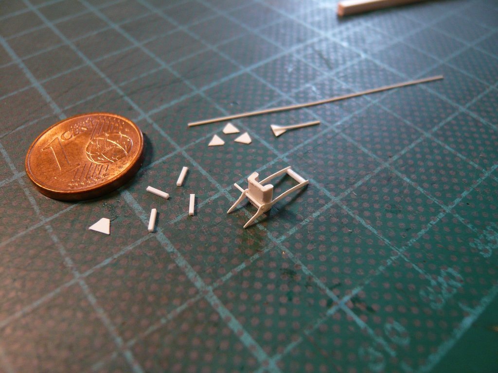 and then glued the axle on the other side as well, 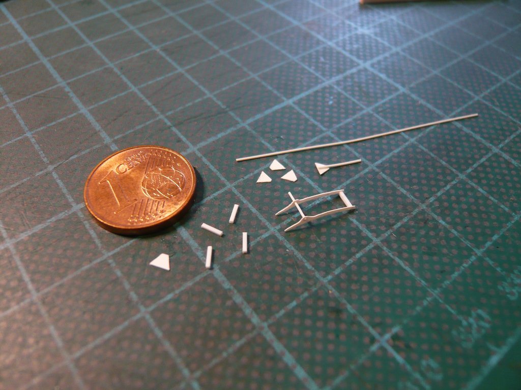 and separated its overhang. For the longer rod attached to the upper axis of rotation, I first glued a rod (Ø 0,25 mm) onto a small styrene triangle (0,13 mm), which is not entirely correct since the bar actually sits between the triangles. 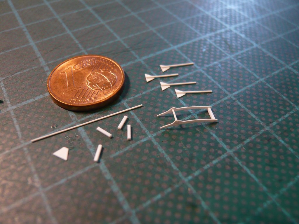 For the struts of the small fork, I first used Evergreen Strips (0,25 mm x 0,5 mm). 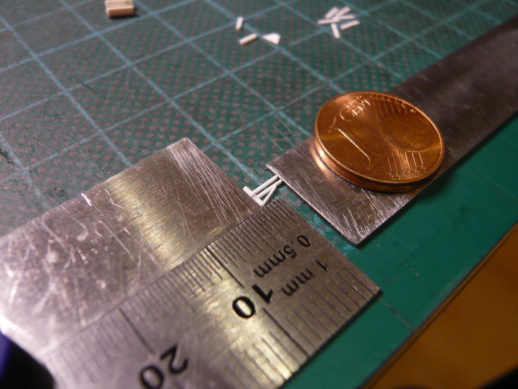 But when I had laid on the longer rod and compared this thing with the filigree structure of the side parts (0,13 mm), 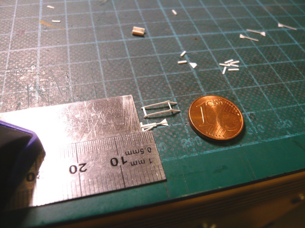 I saw that the proportions couldn't be right, which didn't convince me overall and therefore couldn't stay like this.  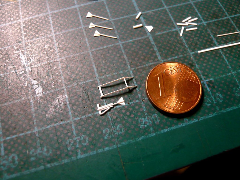 So I measured all the dimensions again more precisely, after which I used a rod (Ø 0,3 mm) and ground off the Evergreen strips (0,25 mm x 0,5 mm) for the struts between two cosmetic polishing files to a thickness of approx. 0,15 mm, what should then match better with the sickles. Then I also had the daring idea  to glue the rod between the triangles, that only had a usable side length for clamping of about 1,5 mm, which is why I was rather skeptical about being able to glue them accurately to the rod. to glue the rod between the triangles, that only had a usable side length for clamping of about 1,5 mm, which is why I was rather skeptical about being able to glue them accurately to the rod. 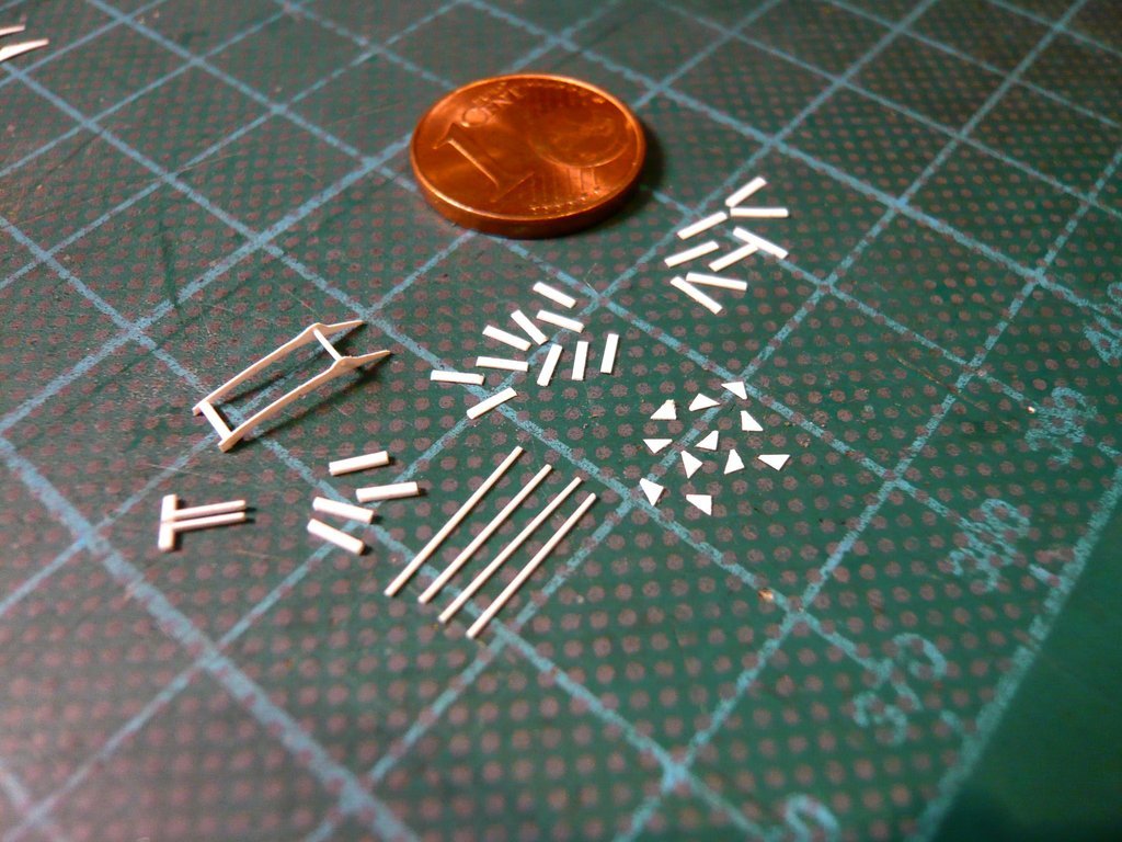
__________________
Greetings from Germany Manfred Under construction: Launch Pad 39A with Challenger STS-6 (1:144)
|
|
#2700
10-23-2022, 05:22 PM
|
||||
|
||||
|
But that was too much of a good thing, which is why I remembered to another solution,
which I have used already successfully in such cases several times, namely with the MLP-SSWS-Pipes, and most recently also with the Crawler Gear Boxes. 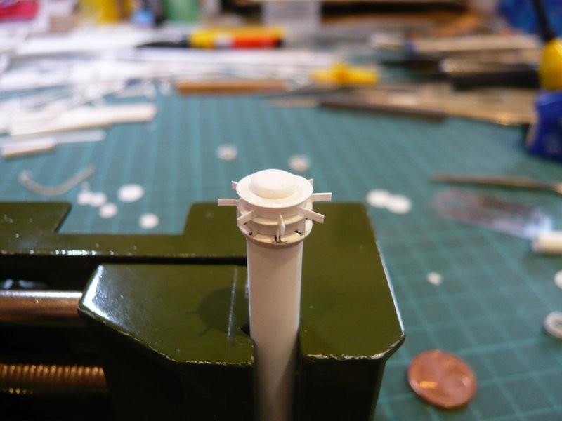 OMG, that was already 6 years ago ...  So I've cut narrow Styrene strips (0,13 mm) with the height of these triangles (1,2 mm) and glued them from both sides onto the rod (Ø 0,3 mm), which could still be done with appropriate fixation, 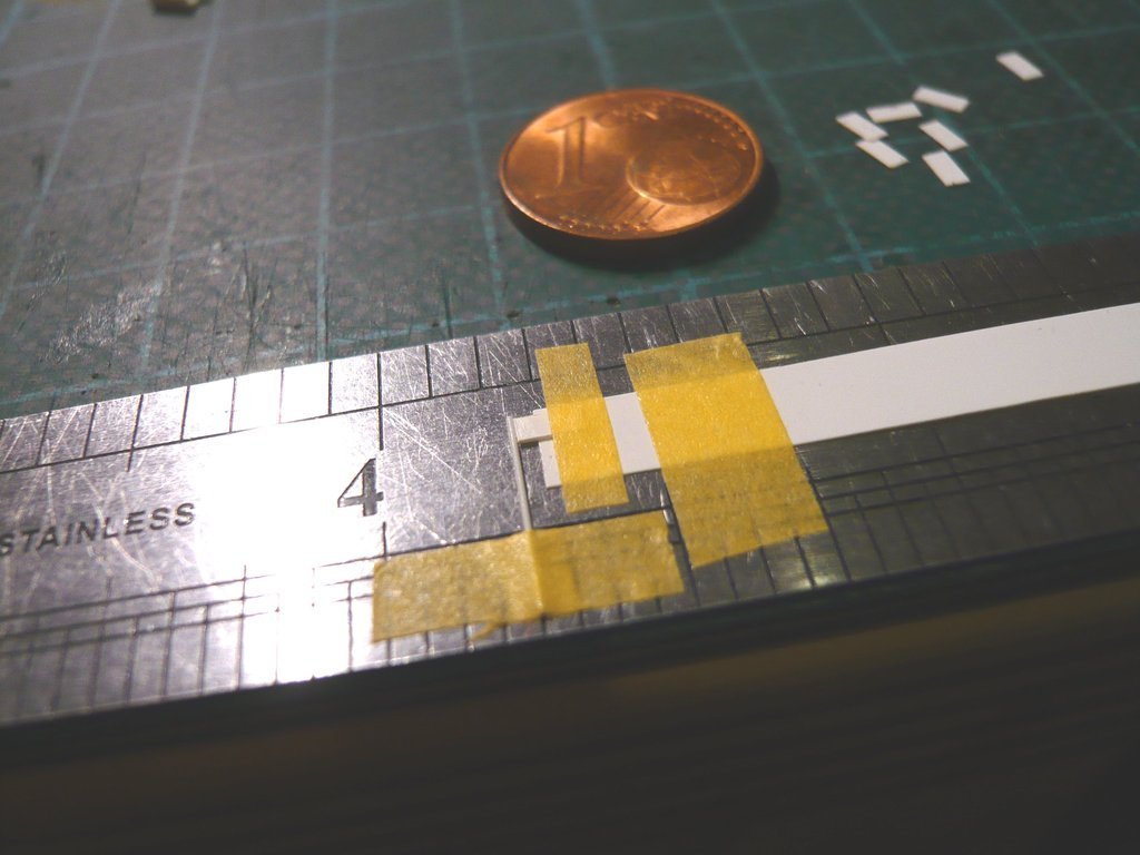 and with the necessary patience and caution. 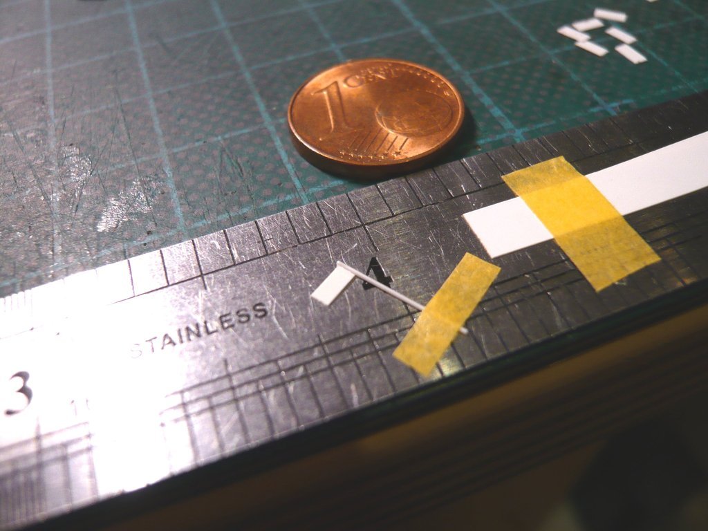 Here's a comparison of both variants, whereby one hopefully can see the difference. 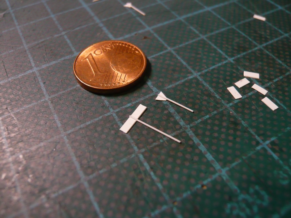 And then the strips only needed to be carefully cut off at an angle, 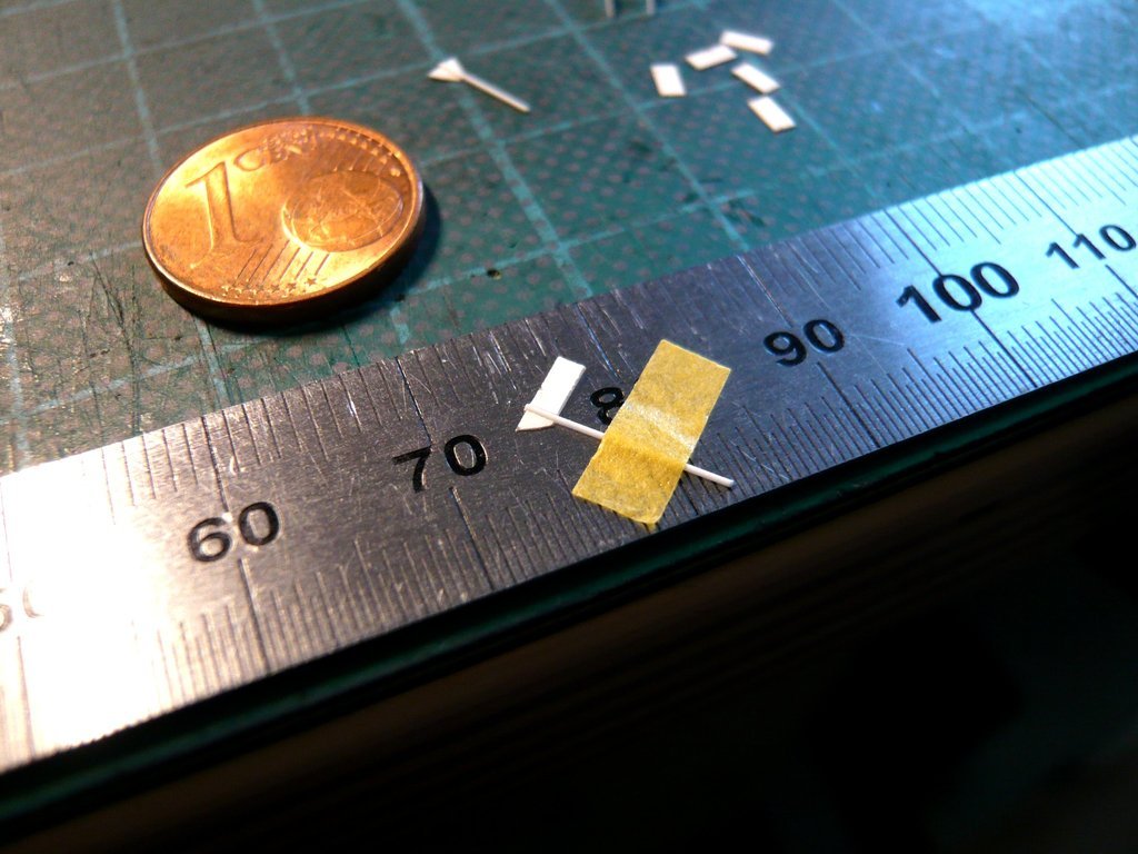 and with this result I was more like satisfied already. 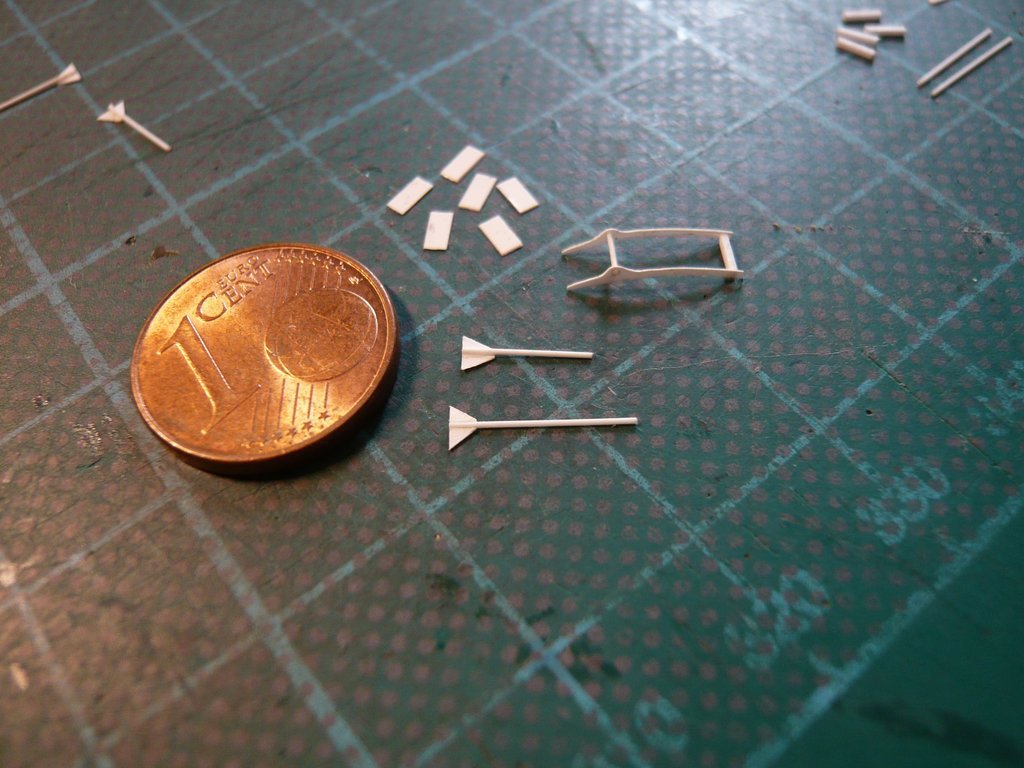 As a test, I've laid this rod on top of the rotary axis, which of course it will later be glued in front of the axis. 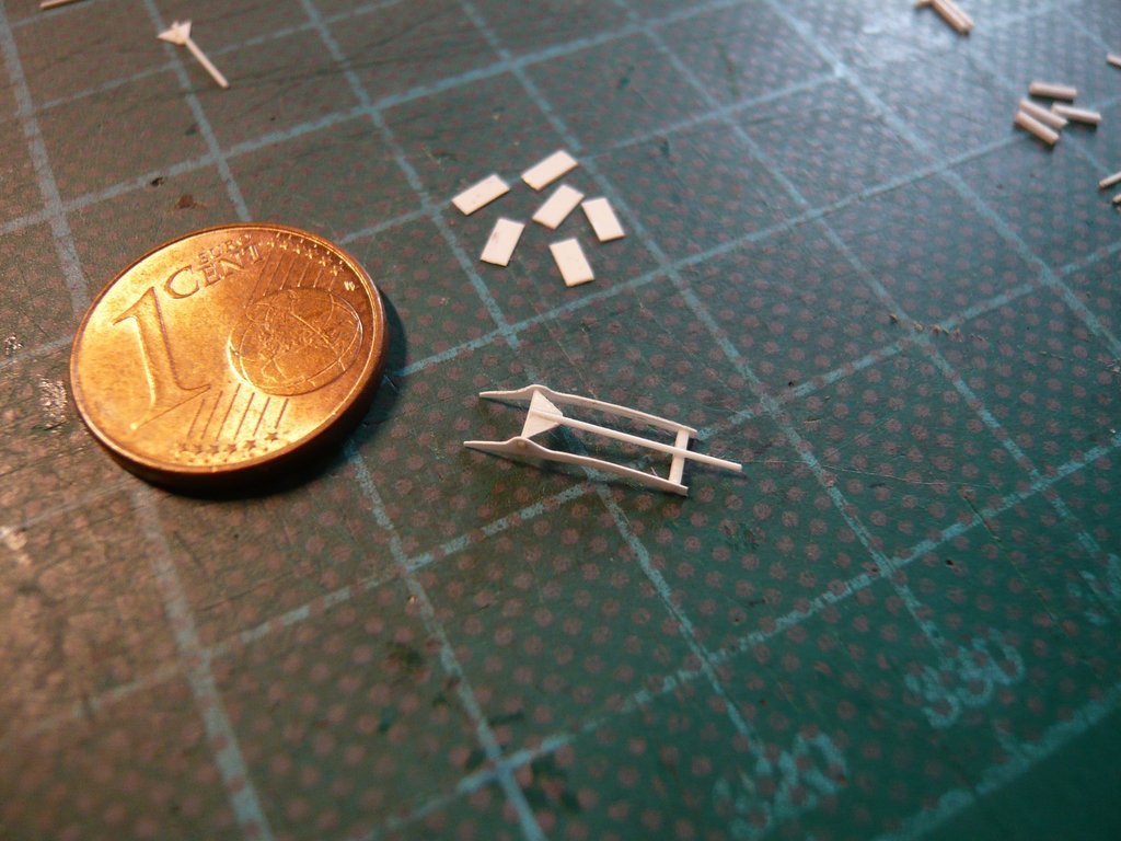 So the picture is slowly rounding itself off, and with it I want to leave it at that for today and wish you a pleasant evening.
__________________
Greetings from Germany Manfred Under construction: Launch Pad 39A with Challenger STS-6 (1:144) Last edited by spacerunner; 11-13-2022 at 04:38 PM.
|
 |
|
|


 Linear Mode

