


|
|
|
#2731
 12-30-2022, 06:40 AM
|
||||
|
||||
|
Hello everybody,
I hope you tolerated all the culinary delights well and were happy about the presents.  Now that the holidays are over, I want to get back to the crafting table and carry on a little further to finally finish these tricky Door drives.  In the meantime, I've also gotten a little more clarity about the possible function of this special drive and transmission technology, what is always part of it for me.  Doing it I found out that my Coupler (2) is a Bevel Gearbox, through which the shafts in the horizontal pipes (6) are driven, which are connected to the Screw Jacks, which are connected with the upper linkages of the Door Actuators on the canister doors, by means of which the doors can be opened and closed.   Source: NASA (STS-135) Such a Bevel Gearbox has the following basic structure, whereby the implementation of a rotary movement of a drive shaft within an angle of 90° to an output shaft is effected by means of bevel gears. 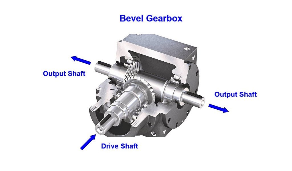 Source: drivelines.co.uk And this Output shaft is located in the horizontal pipes (6) on either side of the door operator and is connected at both ends with Screw Jacks. The lifting movement of the rotating spindle with trapezoidal thread is carried out via a worm gear, which is located in a gear housing, as can be seen in the image on the right. In the lower area, the vertical lifting spindles are surrounded by a protective tube and in the upper area they are covered by black Folding bellows to protect against dirt, which are folded when doors are opened and unfolded when doors are closed. 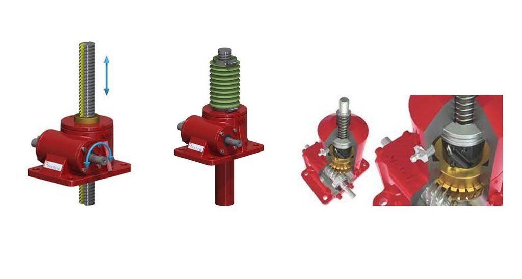 Source: mechjacks.com Next I want to scratch the gray Pneumatic Unit with the dome-shaped Cover (4) in front of the Housing (9), whatever these parts may be called, which unfortunately I haven't been able to find out yet.   Source: NASA (STS-135) Anyway, both parts in 1:160 are pretty small, but more on that in the next post.  
__________________
Greetings from Germany Manfred Under construction: Launch Pad 39A with Challenger STS-6 (1:144) 
|
|
#2732
12-31-2022, 04:16 PM
|
||||
|
||||
|
Hello everybody in the old year,
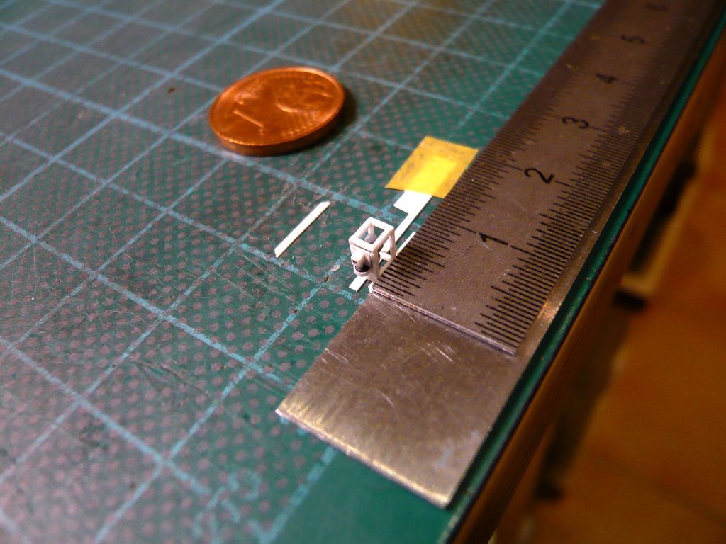
and so let's go right ahead with the midgets of the Pneumatic Unit. For the Housings (9) I've sanded two Styrene blocks (0,7 mm x 1,3 mm x 1,6 mm), and for the dome-shaped Cover (4) I did use a rod (Ø 1 mm x 1 mm) painted gray. 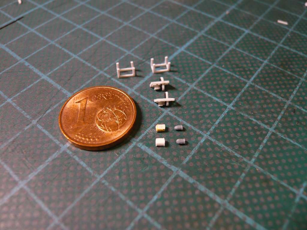 The small plugs were glued on in the usual way by using the proven fixation between the steel rulers. 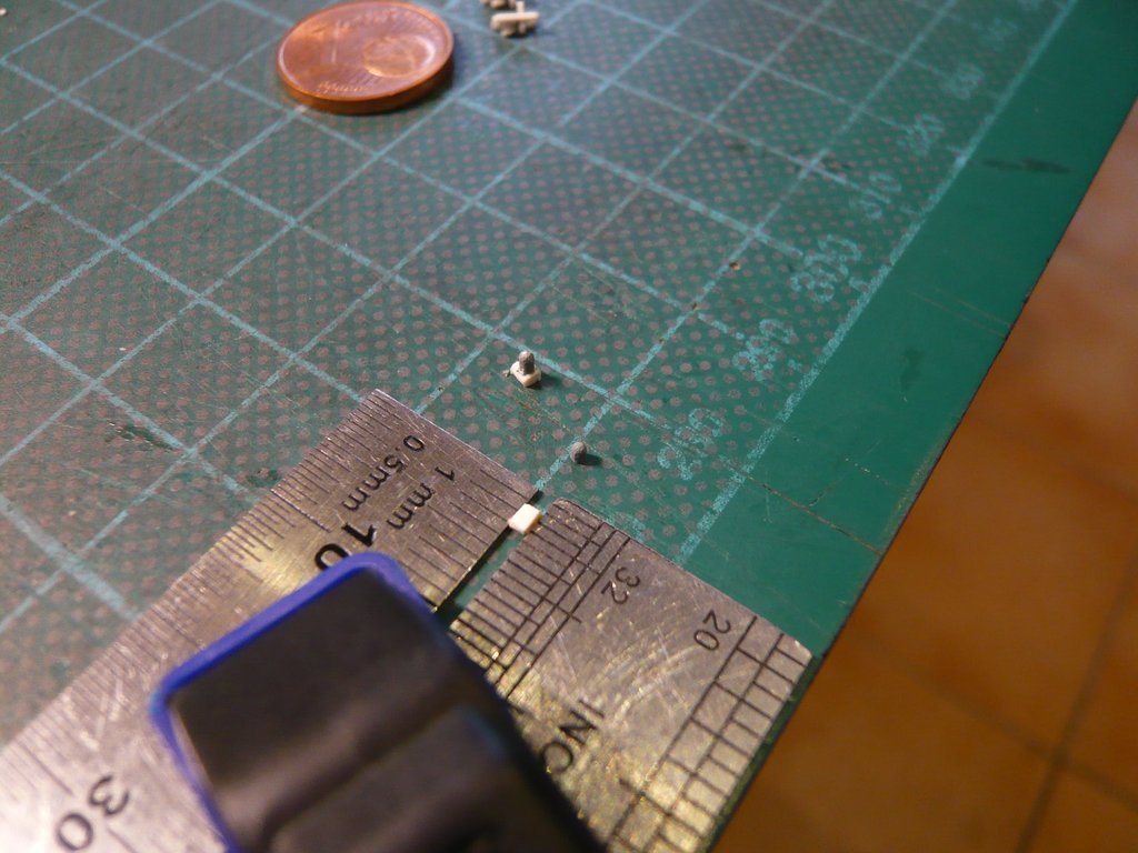 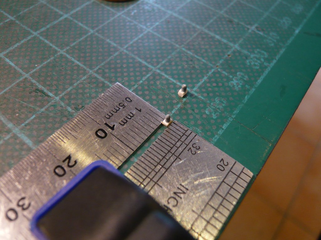 The tiny Screw (8) on the Bevel Gearbox (2) I've hinted with a Fineliner (0,05 mm). 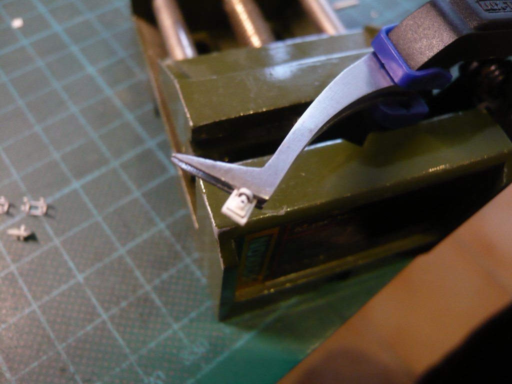 Now the Housings (9) of the Pneumatic Unit still had to be painted grey, 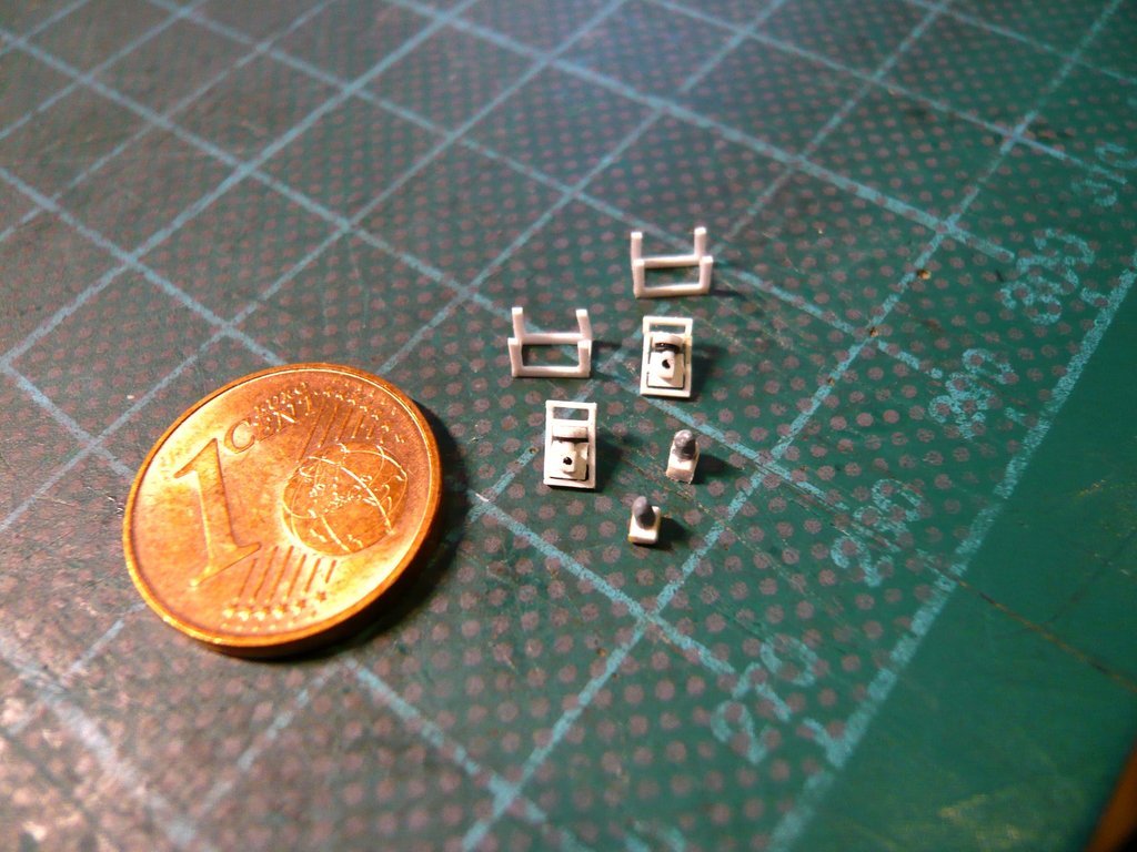 for which I've thought of a clever solution using a Paulaner Crown cap as a turntable with a tape strip glued on in reverse,  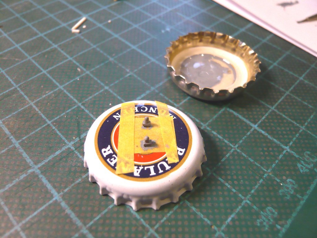 which also worked fine. 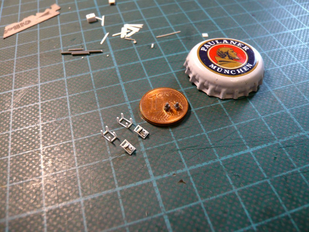 Now all I have to do is glue these things to the underside of the frame onto the rear Gear part (1), which should become pretty tricky,  which is why I'm going to try that next year. which is why I'm going to try that next year. So it's time to say goodbye for this year and I wish everyone a happy New year. Come across well and stay tuned! 
__________________
Greetings from Germany Manfred Under construction: Launch Pad 39A with Challenger STS-6 (1:144)
|
|
#2733
01-01-2023, 02:54 AM
|
||||
|
||||

__________________
Greetings from Germany Manfred Under construction: Launch Pad 39A with Challenger STS-6 (1:144)
|
|
#2734
01-02-2023, 01:02 PM
|
|||
|
|||

|
|
#2735
01-02-2023, 04:21 PM
|
||||
|
||||
|
Thanks Marcell,
 and all the best for you too.
__________________
Greetings from Germany Manfred Under construction: Launch Pad 39A with Challenger STS-6 (1:144)
|
|
#2736
01-02-2023, 04:24 PM
|
||||
|
||||
|
Hello everybody in 2023,
I hope you all slipped in well and are in good spirits. I also want to get off to a flying start and show how I assembled the Door drive, which consists of limply 20 individual parts if I counted correctly.  Before assembling both frames, however, the Pneumatic unit had to be glued to the rear Gear part (1) of the upper frame, for which I had to come up with a special holding device again,  so that the fragile assemblies do not break down. so that the fragile assemblies do not break down.  And for this, only a magnetic holder was possible, for which the free end of the frame behind the gear part with 1 mm was just enough, And for this, only a magnetic holder was possible, for which the free end of the frame behind the gear part with 1 mm was just enough, 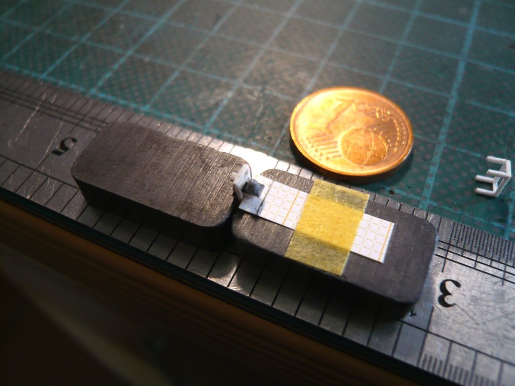 wherefore I also needed a spacer template.  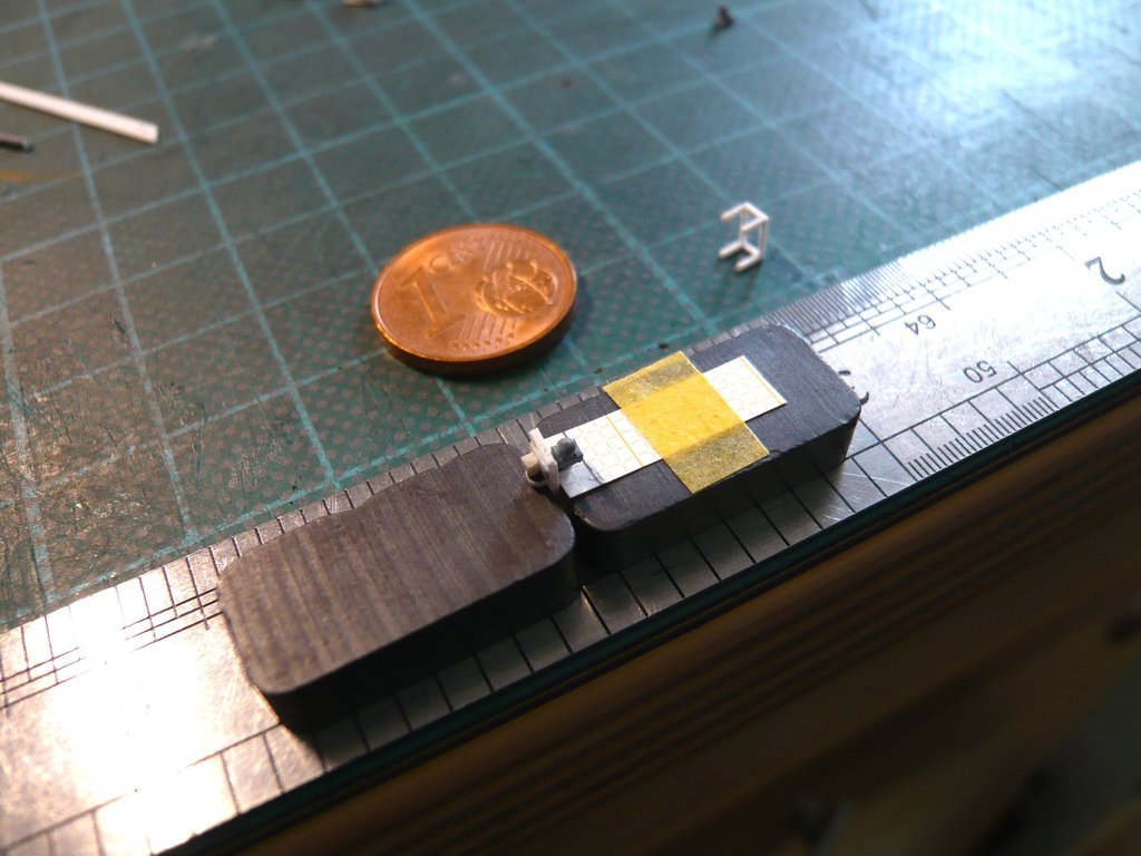 But then came the much more difficult exercise, namely gluing the upper frame onto the feet of this small table. 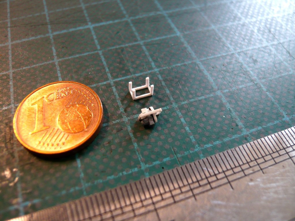 As can be seen from the following images, everything only worked again using special clamping technique, 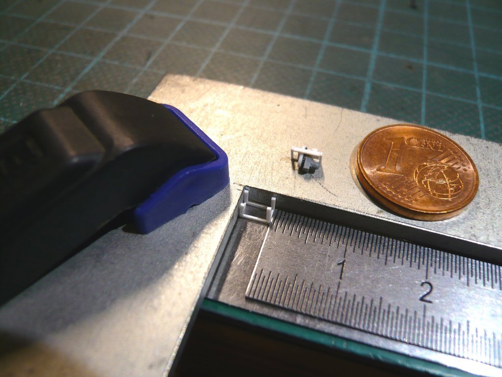 by having the magic touch for this tricky job, 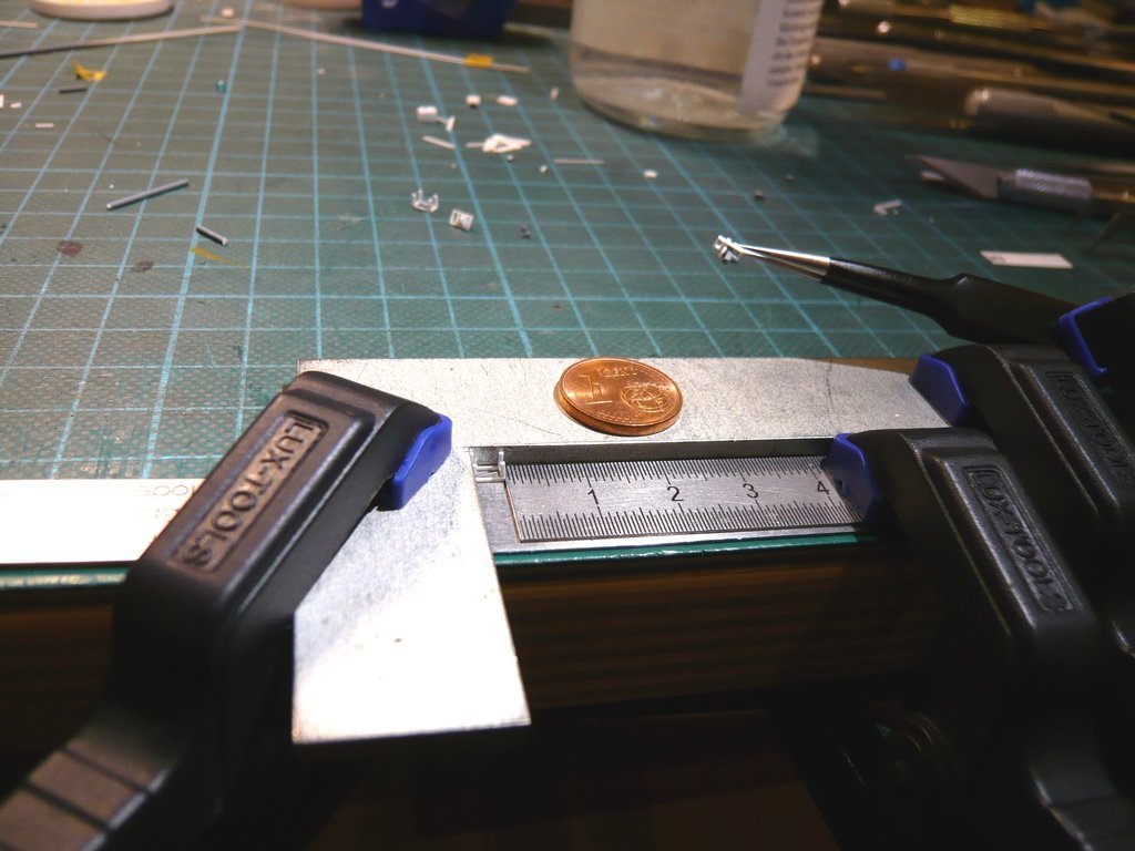 and softly, softly, catchee monkey ...  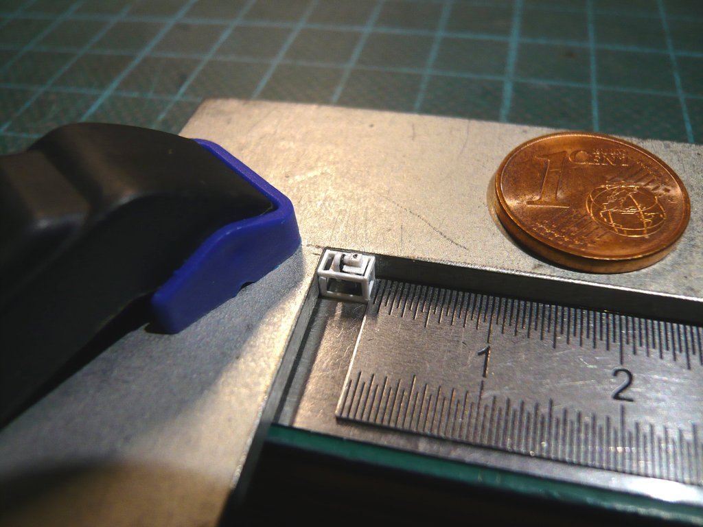 But it finally worked, although it was quite stressful because some struts had to be aligned and partially re-glued. 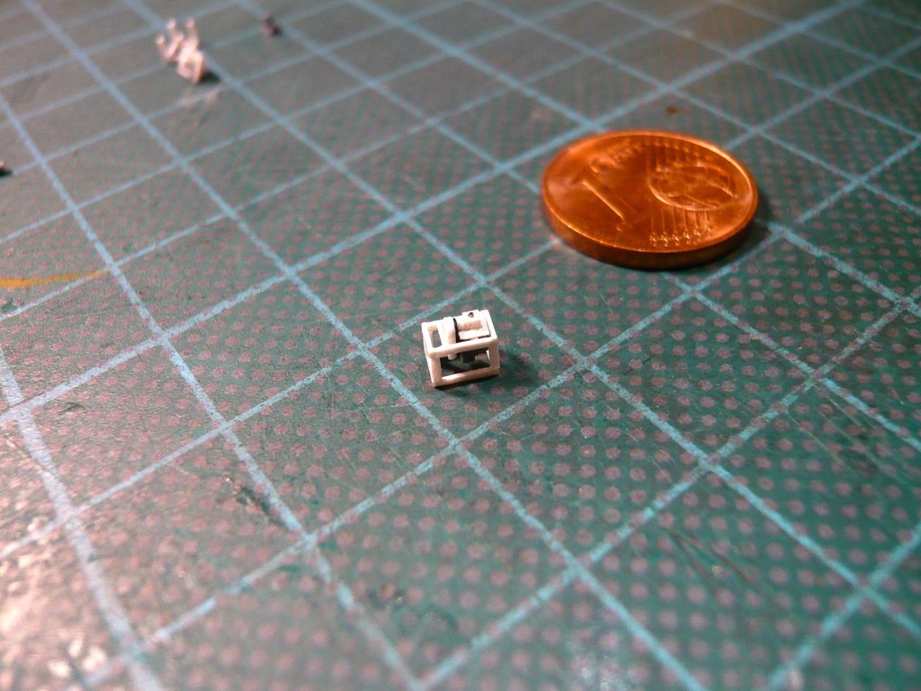 And in the mounting position, the Door Actuator Pneumatic Drive looks quite passable. 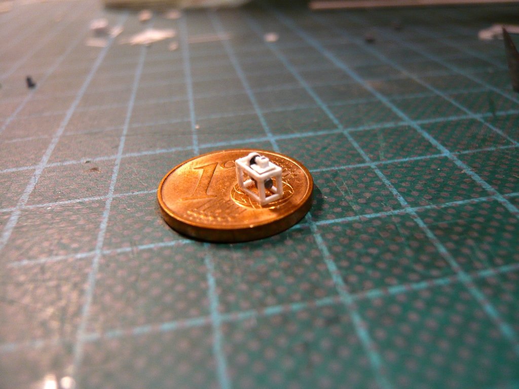
__________________
Greetings from Germany Manfred Under construction: Launch Pad 39A with Challenger STS-6 (1:144)
|
|
#2737
01-02-2023, 04:25 PM
|
||||
|
||||
|
But now the lateral struts, which had been prepared for some time, still had to be glued at the back of the frame,
 here with the strut during a first fitting on the canister, which fitted quite well. 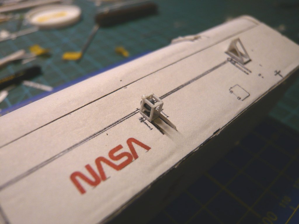 Then the second strut was glued opposite, 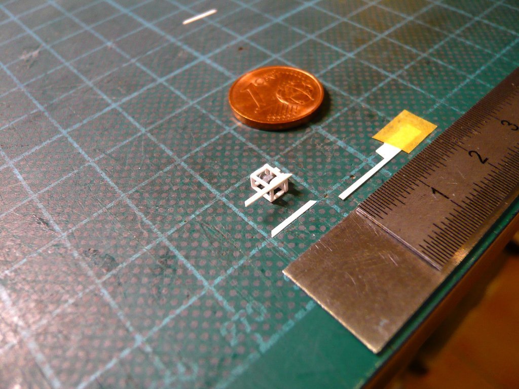 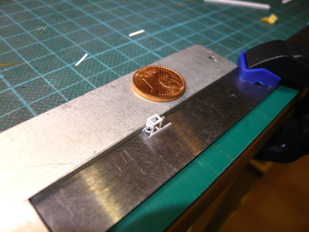 with which the first door drive was finally complete. 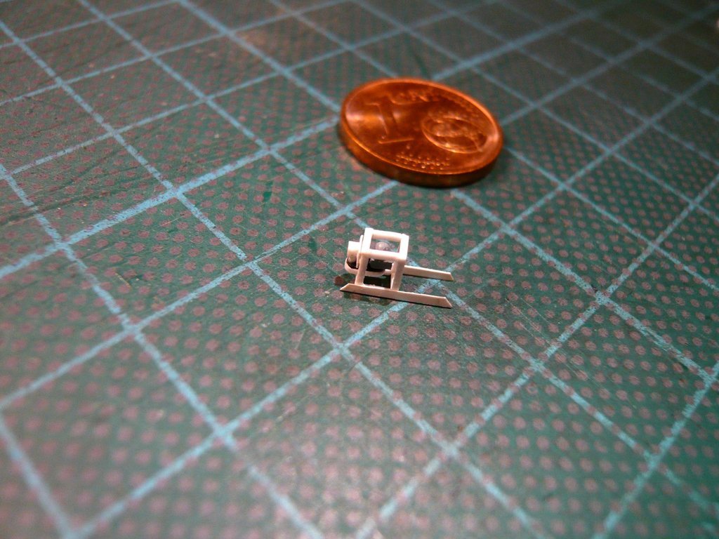 And this is the final test fitting of the drive on the Starboard Side of the canister,  which has withstood my critical eye.
__________________
Greetings from Germany Manfred Under construction: Launch Pad 39A with Challenger STS-6 (1:144)
|
|
#2738
01-05-2023, 06:47 AM
|
||||
|
||||
|
Hello everybody,
and now the Door actuator followed for the other canister side using the same knitting pattern. 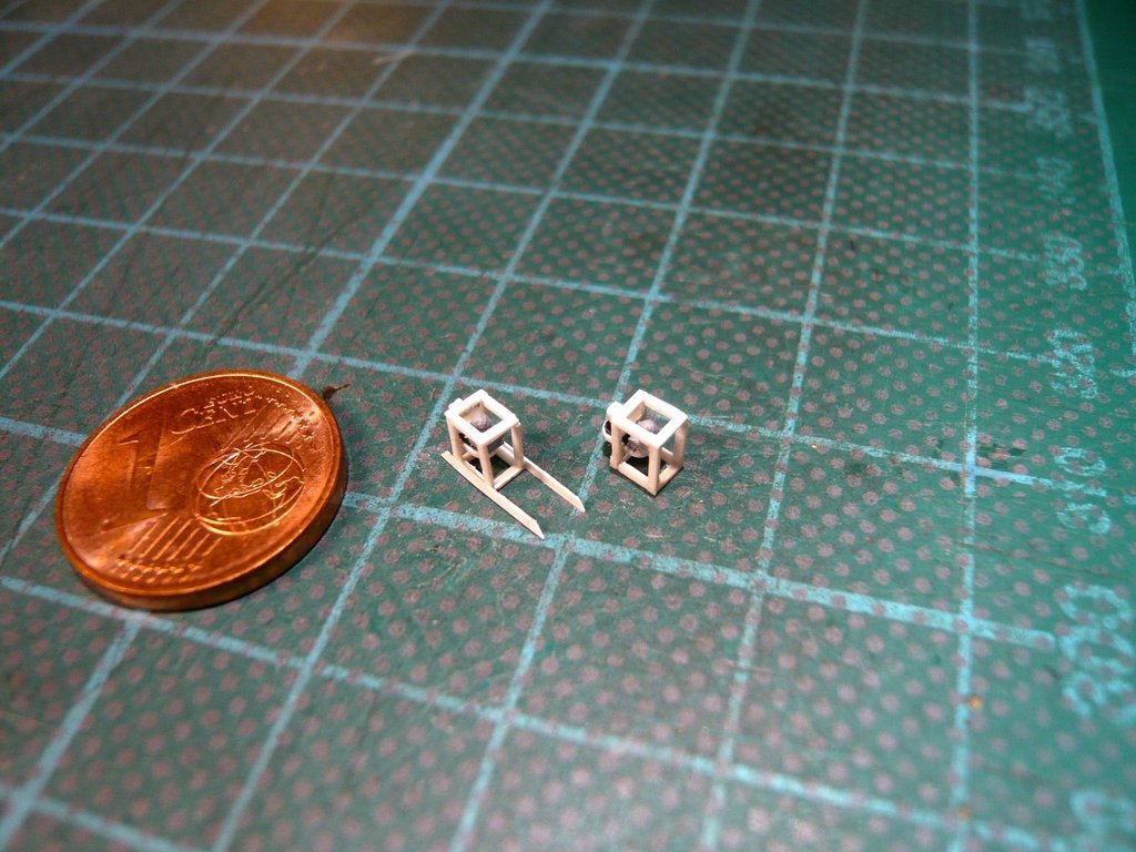 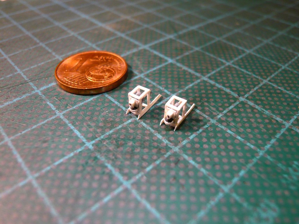 With this the Port Side now also has its door drive. 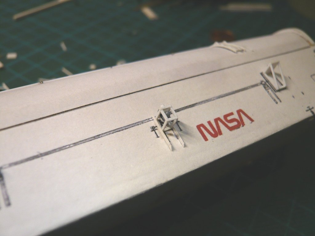 Next up are the bottom linkages of the Door actuators on which the Screw Jacks are mounted.  Source: NASA (STS-135) They are similar to the adjacent Access Platforms in terms of the structure of the mount, but are much narrower and therefore a bit more complicated, as one can see on this section at higher magnification,  Source: NASA (STS-135) which is also good usable for determination of the dimensions needed for scratch building, what is now my next task.
__________________
Greetings from Germany Manfred Under construction: Launch Pad 39A with Challenger STS-6 (1:144)
|
|
#2739
01-06-2023, 12:40 PM
|
||||
|
||||
|
Hello everybody,
and I tackled that right away, which resulted in the following dimensions. Source: NASA (STS-135) In order to keep track of it myself, I marked the determined heights and widths in color, especially since they also were determined by using different reference dimensions (blue). As reference dimensions I've used the dimensions of the Wall braces of the door actuators, which are identical to those of the Screw jacks. But that's still not all the dimensions I need. A few widths from a front view of the screw jack are still missing, which cannot be determined exactly from this slightly slanted side view. And for that this photo is a good reference. Source: NASA (STS-135) Determining the dimensions is always extremely time-consuming and a tiring torture for the eyes, but unfortunately I have to bite the bullet again and again , because unfortunately nothing can be scratched without dimensions. The Wall braces I've put aside some time ago already. 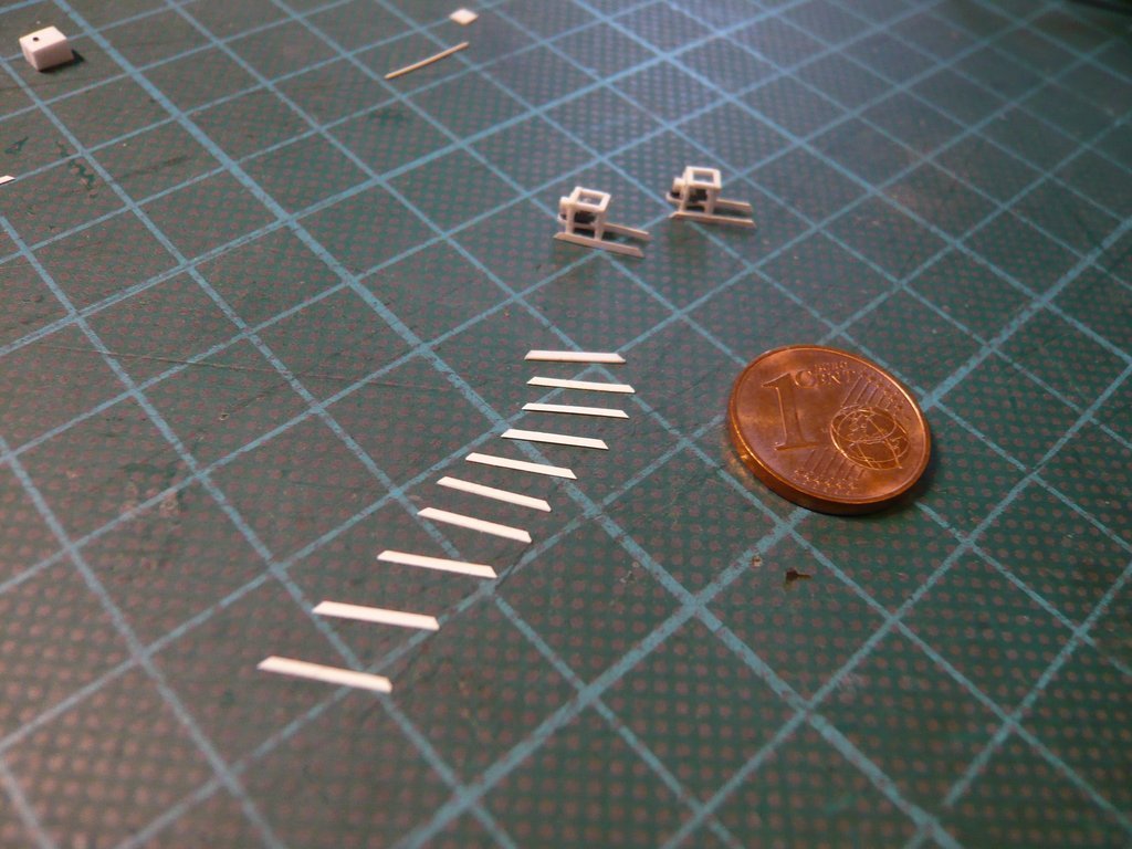 Now I have to go through my stock and see which profiles I can use for the remaining parts.
__________________
Greetings from Germany Manfred Under construction: Launch Pad 39A with Challenger STS-6 (1:144)
|
|
#2740
01-10-2023, 01:21 PM
|
||||
|
||||
|
Hello everybody,
well then let's get to the mini parts for the Screw Jacks, which I have to scratch four times for both sides of the canister. Since the Frame struts should always have the same length, it is again a matter of a reproducible cutting of the strips, for which I will use Evergreen strips (0,25 mm x 0,5 mm).  Therefore, the short question to people with a good sense of proportion.  How long do you think the snippets cut with this ruler setting will be?
__________________
Greetings from Germany Manfred Under construction: Launch Pad 39A with Challenger STS-6 (1:144)
|
 |
|
|


 Linear Mode

