


|
|
|
#2771
 02-23-2023, 03:05 AM
|
||||
|
||||
|
Thanks whulsey for looking in to me again.
 As you can see, it's always worth and therefore stay tuned.  
__________________
Greetings from Germany Manfred Under construction: Launch Pad 39A with Challenger STS-6 (1:144) 
|
|
#2772
02-24-2023, 01:33 PM
|
||||
|
||||
|
Hello everybody,
after the provisional fitting of the Outrigger, the parts were now glued together, first the diagonal struts with the holding plate, which later is glued with the Guide shoe.  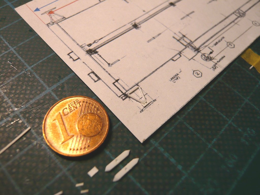 To do this, the two diagonal struts were fixed with tape, after what the upper cross strut and to it the lateral hinge plates could be glued, 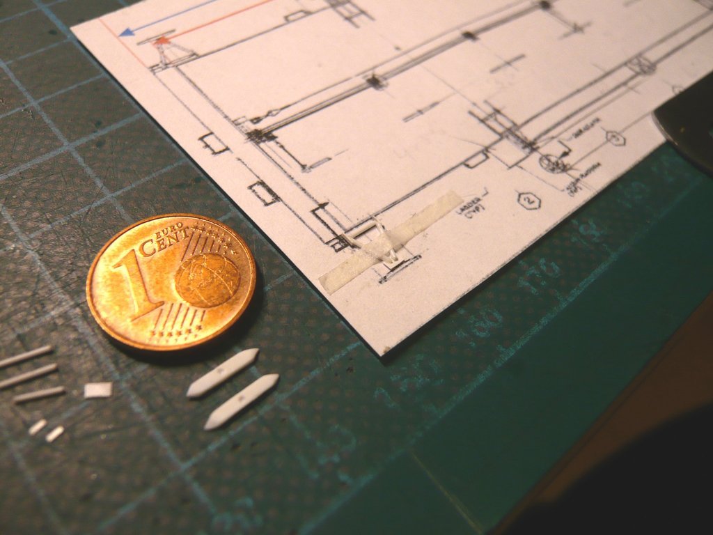 which are articulated in the holders on the side wall for folding and unfolding the outrigger. And here at the latest, compared to the drawing, I noticed that the Guide shoes (8 mm) were a bit too long, which was confirmed by subsequent measurements using photos, what had also to be corrected, similar like the holding plate, which was also a bit too big.  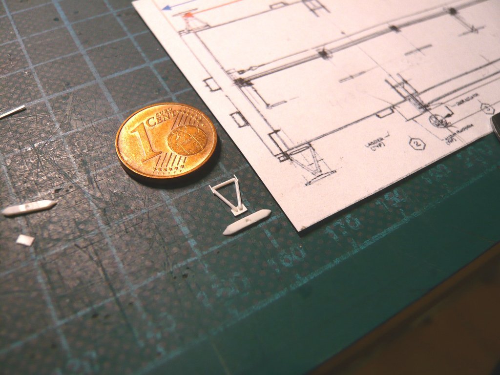 The strips for the holdings (0,13 mm x 0,5 mm x 1 mm) have a small overhang so that they can still be held with tweezers when gluing them to both sides of the hinge strips. 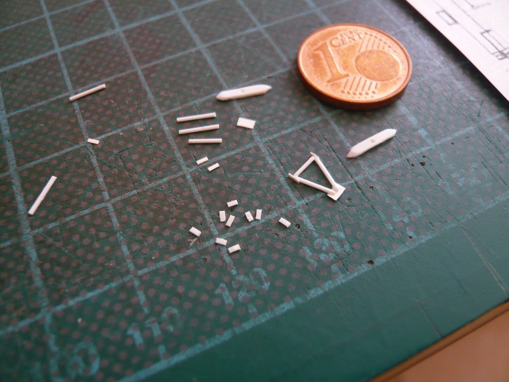 Here first the gluing of the inner parts of the holders, the overhang parts of which were carefully separated with a razor blade. 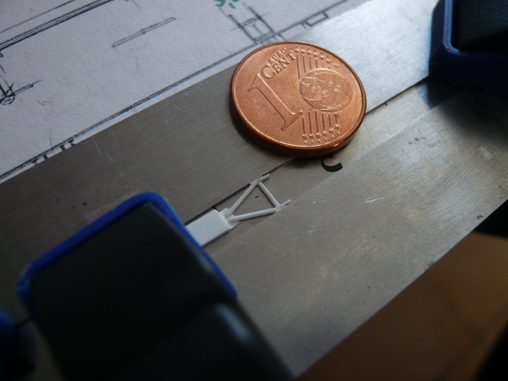 And here the gluing of the outer strips, 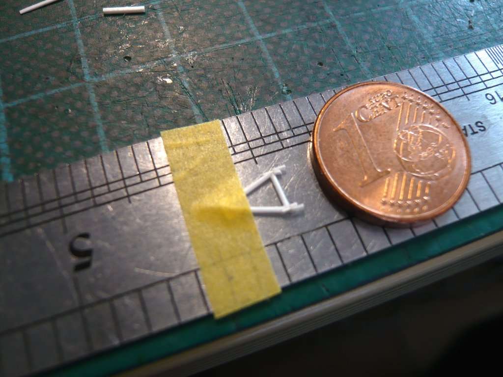 whose overhangs were also separated. 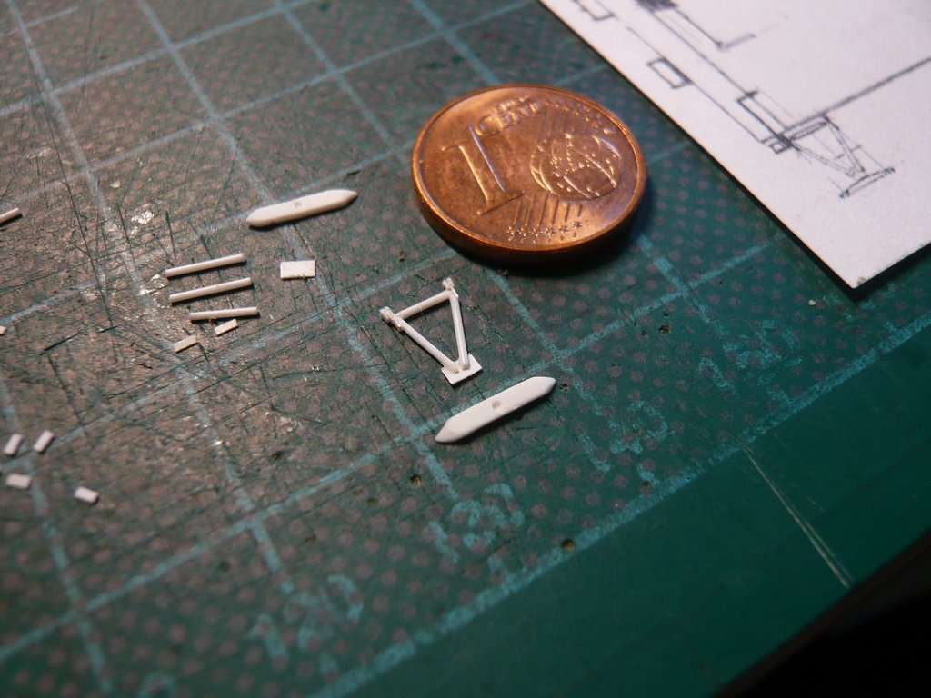 Then the strut linkage was glued to the shortened guide shoe. 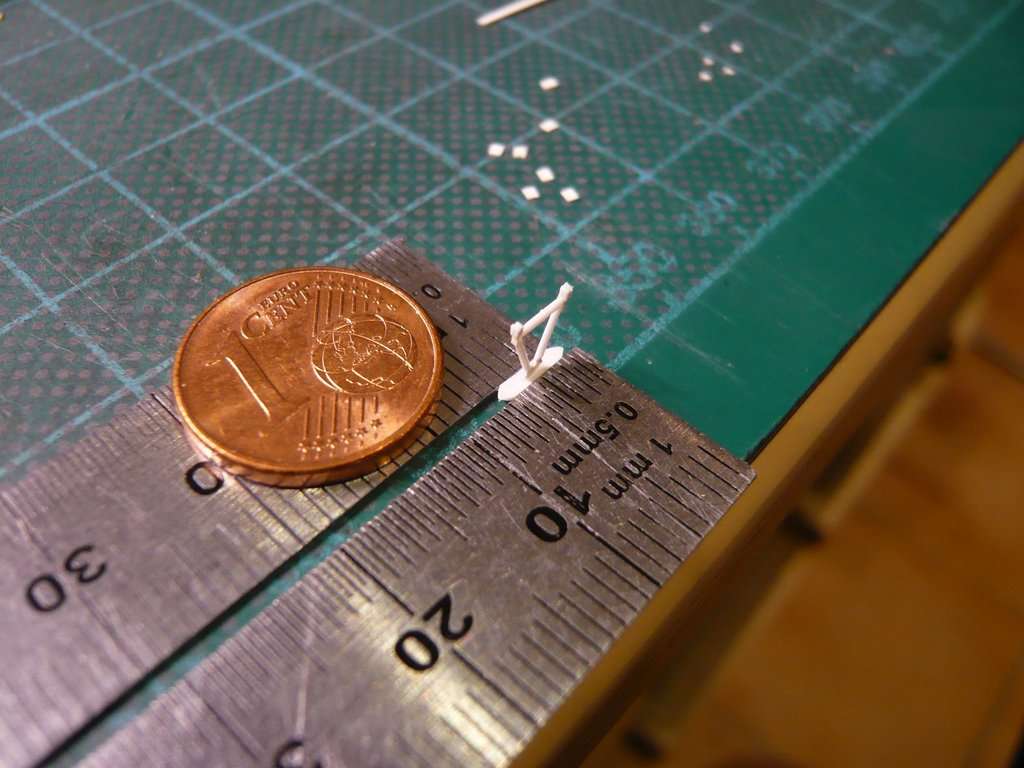 The length of the slanting support strut was determined using this small template to 7,5 mm. 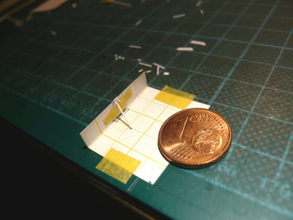 As one can see on this image, all mountings sit on small base plates (0,13 mm x 1 mm x 1,5 mm), which should not be missing either,  Source: NASA (STS-135) but had to be fixed again for gluing. 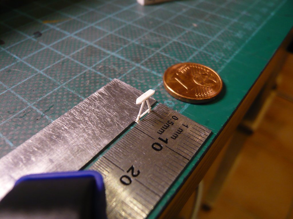 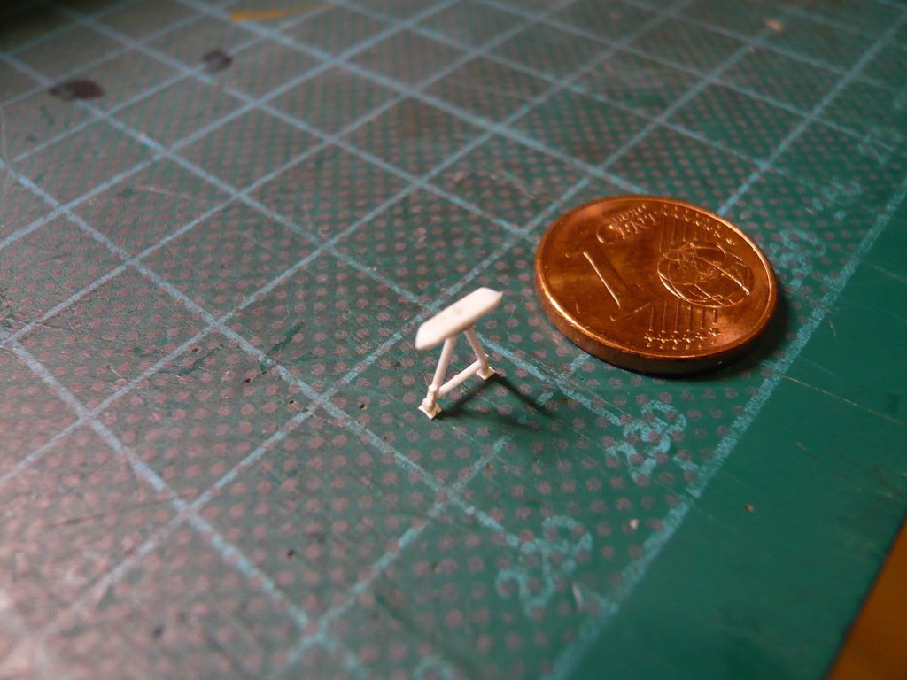 The slanting support strut is also locked in both positions in a holder that I glued together with the base plate at the foot of the strut. 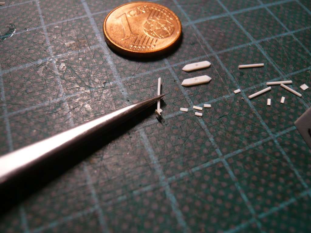 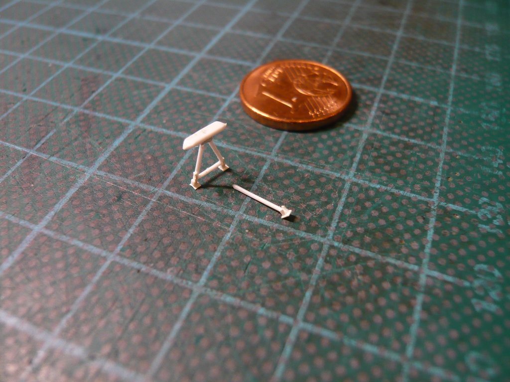 And then I've tried the outrigger on the canister only without the support strut, 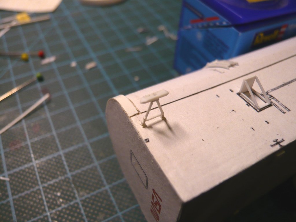 which looks pretty well.  All of these fragile structures are only glued onto the canister at the end so that they cannot be damaged beforehand.
__________________
Greetings from Germany Manfred Under construction: Launch Pad 39A with Challenger STS-6 (1:144)
|
|
#2773
02-26-2023, 11:50 AM
|
||||
|
||||
|
Hello everybody,
today I took on the Lifting Trunnions for lifting and transporting the canister, which are located at different heights on both sides at its bulkheads.  Source: NASA (STS-135) As one can see in this image, the Lifting trunnions consist of three parts, a cylindrical base on which the trunnion with a slightly smaller diameter sits, and an outer cover plate,  Source: NASA (STS-125) which is probably screwed to the trunnion to secure it after the crane's Lifting plate has been attached.  Source: NASA (STS-135) And these are the prepared parts, the white base (Ø 1,2 mm x 0,5 mm), the gray trunnion (Ø 1 mm x 0,5 mm) and the black cover plate (Ø 1,2 mm x 0,25 mm) that I made with my Punch & Die Set. 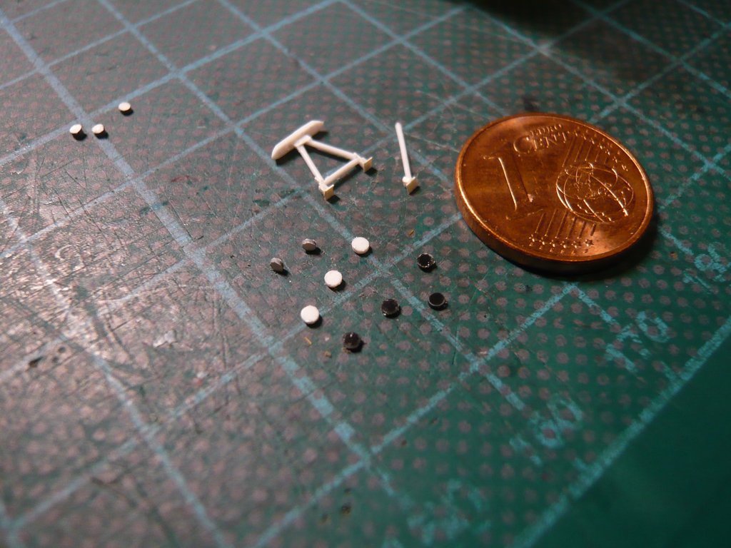 The tiny parts were glued with UHU CA in the tried and tested locking mechanism between the rulers. 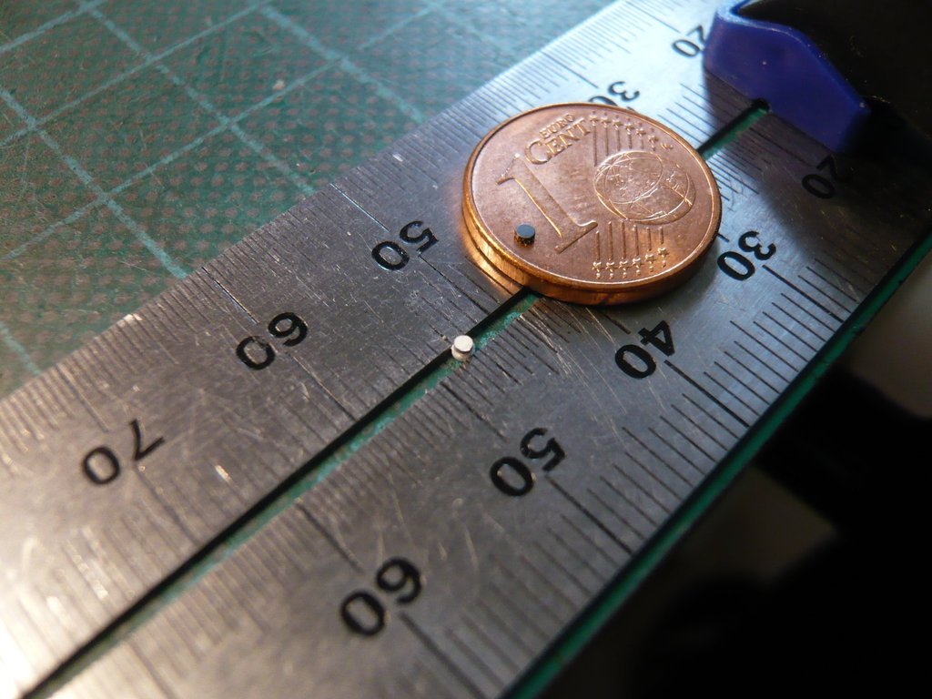 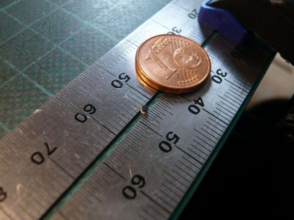 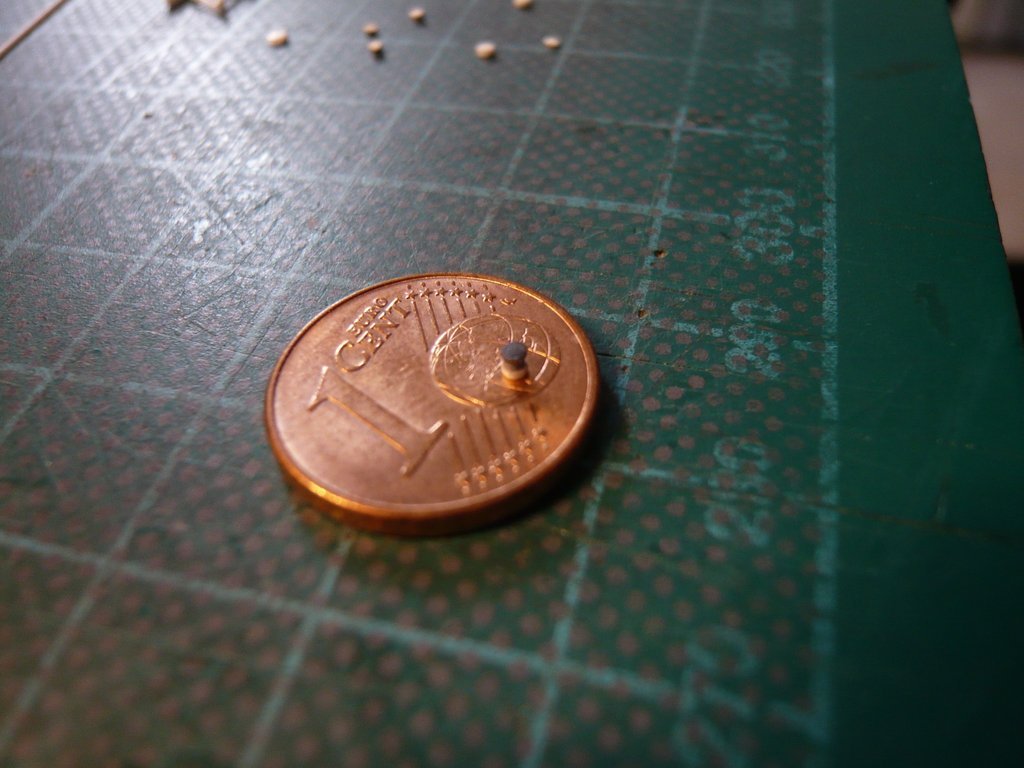 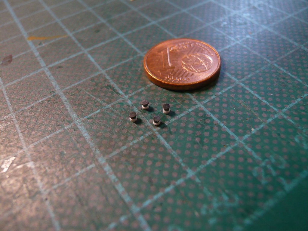 This was followed by the gluing of the lifting trunnions, first on the Port Side of the canister, 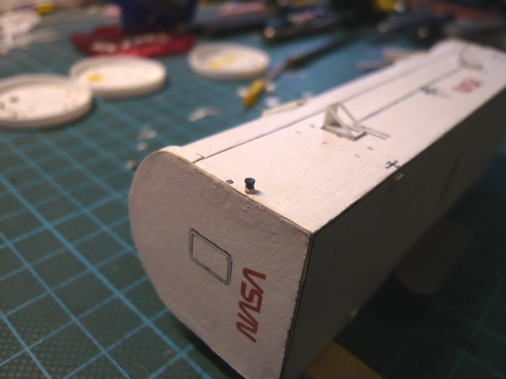 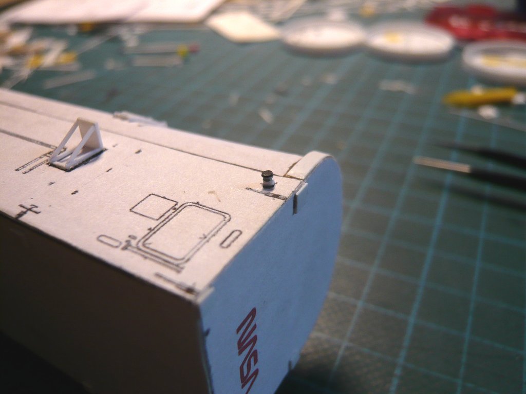 and then on the Starboard Side. 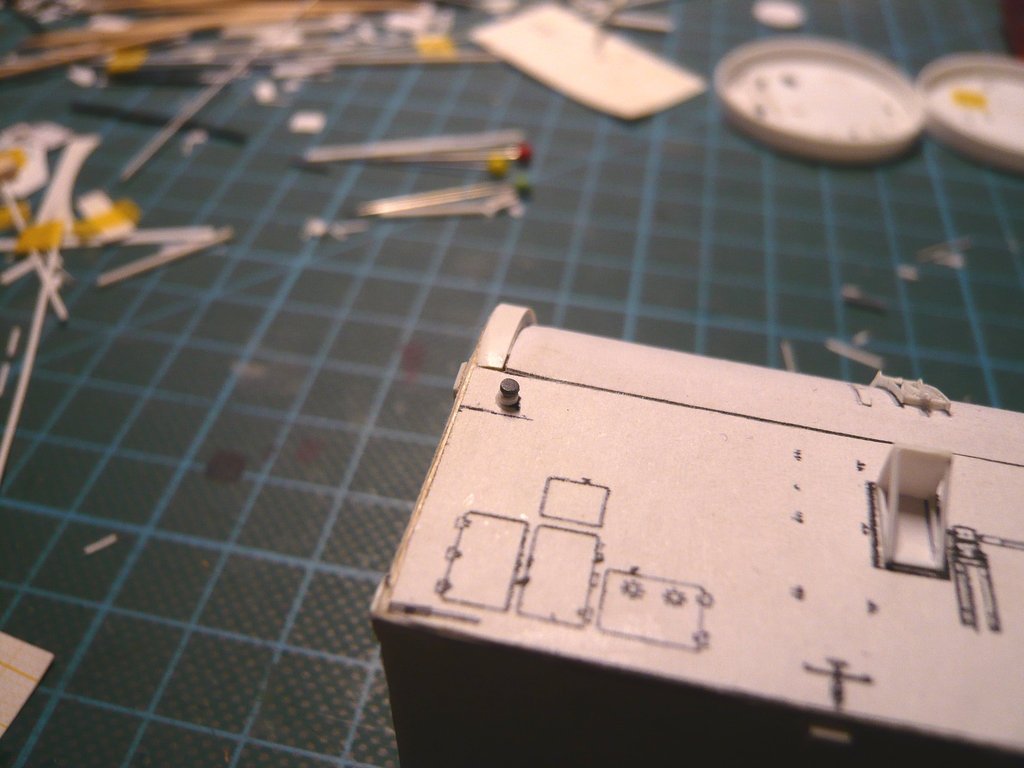 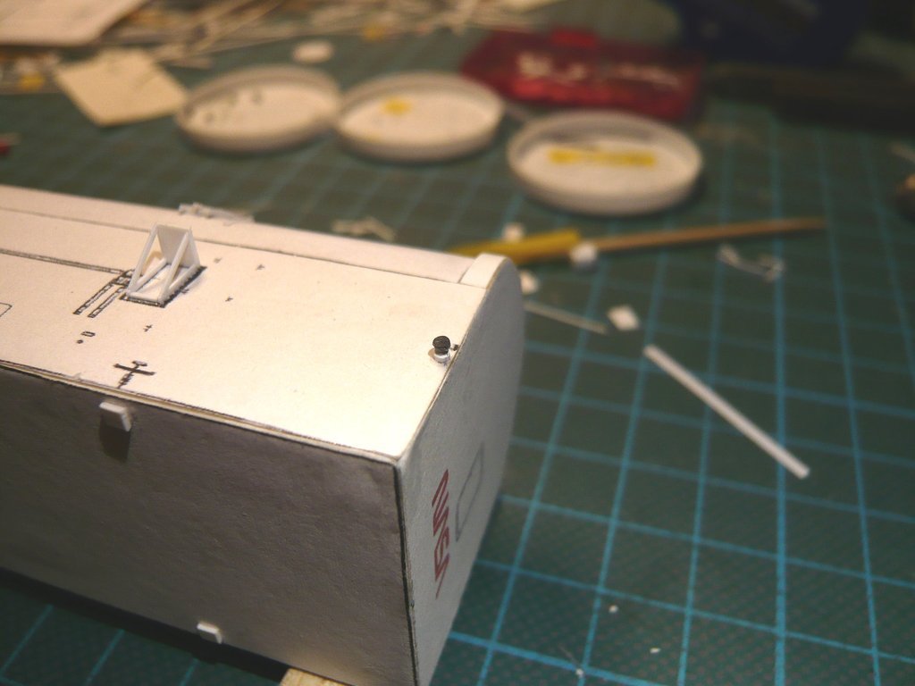 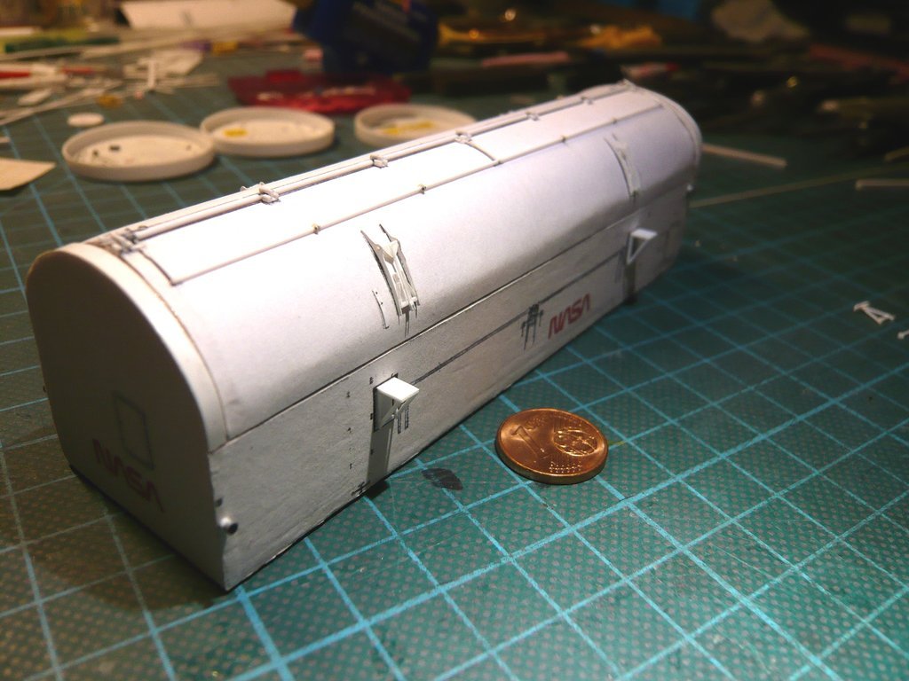 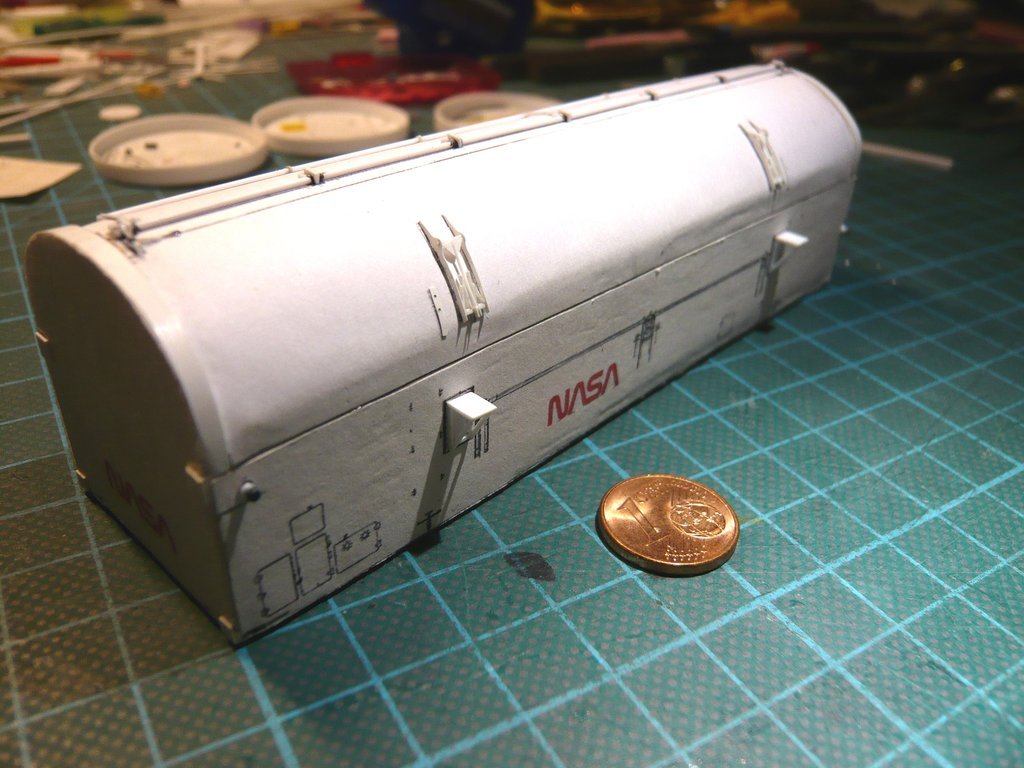 In the meantime, the vertical support strut has also been glued at the Outrigger, 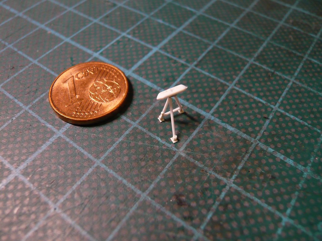 and here the complete outrigger has been positioned on the Port side for a test, which looks quite neat. 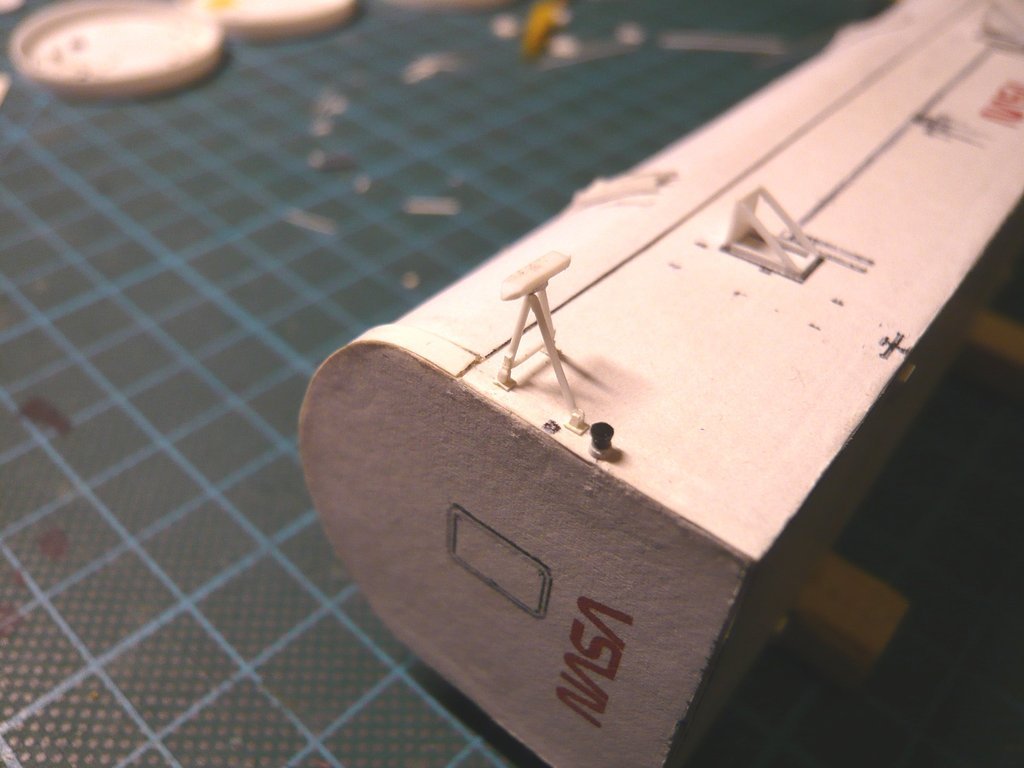 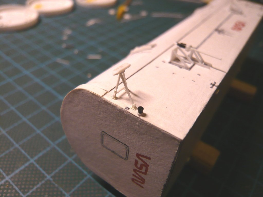 Now all that's missing is the outrigger for the Starboard Side, which will now follow.
__________________
Greetings from Germany Manfred Under construction: Launch Pad 39A with Challenger STS-6 (1:144)
|
|
#2774
03-02-2023, 12:52 PM
|
||||
|
||||
|
Hello everybody,
for the sake of completeness, here is the lower Support strut bracket of the Outrigger required when folded, 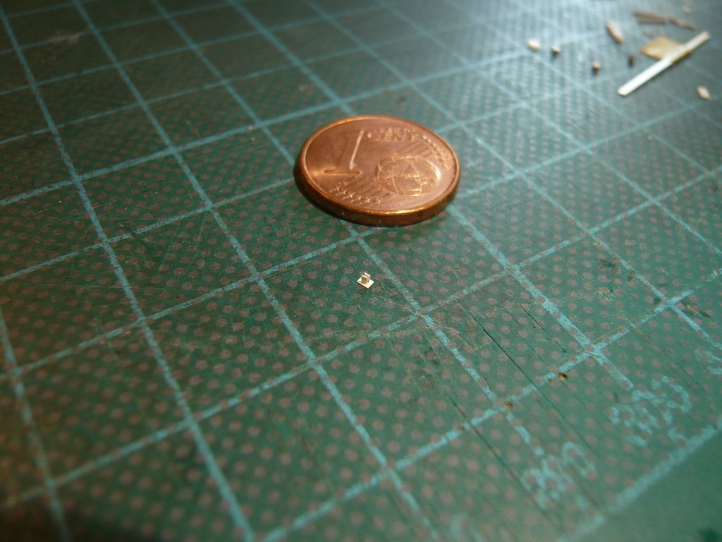 and here its later position on the Port Side of the canister. 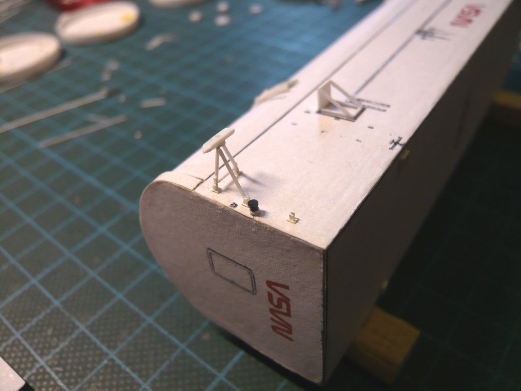 Although my size comparison using the Eurocent is always very impressive,  the comparison of the outrigger with a Can Crew worker shows the actual relation in the model scale 1:160, which is otherwise difficult to imagine. the comparison of the outrigger with a Can Crew worker shows the actual relation in the model scale 1:160, which is otherwise difficult to imagine. 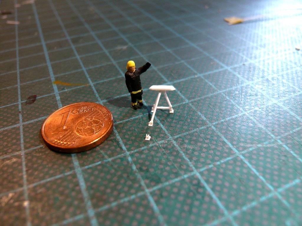 Even more impressive are original photos like this one, on which workers dismantle the Guide Shoe on an Outrigger.  On it one can even see the handle for locking the support strut in the various positions, which I do without because with Ø 0,1 mm x 0,5 mm x 1 mm it would really be too tiny. On it one can even see the handle for locking the support strut in the various positions, which I do without because with Ø 0,1 mm x 0,5 mm x 1 mm it would really be too tiny.  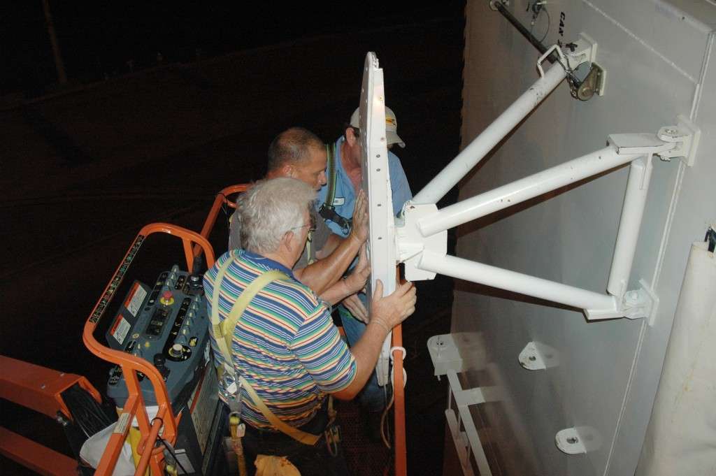 Source: NASA (Jim Grossmann) But then I still have to correct my assumption from the last post about the screwing of the Cover disk on the Lifting trunnion.  I came across this because I remembered a picture my friend James MacLaren took of the Payload Canister just before it was attached to the lifting block of the 90-ton Payload Hoist with its Spreader beam, contained in his documentation Space Shuttle Launch Complex 39-B Construction Photos - Page 9 wherefore I've asked him regarding the red-lettered parts.  In addition to the parts that are already known, you can see the Spreader beam with the lifting plates and on the left in the image one of the two Guide Rails for guiding the Guide Shoes when lifting the canister up to the Payload Changeout Room (PCR).  Source: James MacLaren And if anyone is familiar with these things, then it's him who worked 5 years during building the Launch Pad 39-B and knows the RSS inside out. He also has a large pool of detailed NASA drawings, which he is linking to in his documentation and explains down to the last detail.  Thereupon he has sent me this drawing, on which he highlighted the Lifting Plate, which has a slotted hole with two different-sized openings, which is a simple but ingenious solution for accommodating the Lifting trunnion.  Source: James MacLaren This holds the spreader-beam in such a position to allow the lifting plates hanging from the lifting cables to be passed through the larger opening over the lifting trunnions and the beam then can carefully be lifted, fixing the trunnions in the smaller opening of the plates. This special lifting plate I had also noticed in a photo sent by my friend Richard Chamberlain, who was a member of a Can Crew, cause I still haven't tinkered with these details more closely that time.  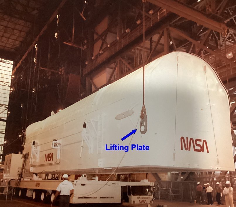 The Canister hoisting system and its entire handling is so complex and demanding,  but at the same time very interesting, so I can commend all interested guys highly the Page 52: A Lighter Moment in a Heavy Place, and a Deep Dive into the Canister Hoisting System in James MacLaren's documentation The Construction of Space Shuttle Launch Complex 39-B. but at the same time very interesting, so I can commend all interested guys highly the Page 52: A Lighter Moment in a Heavy Place, and a Deep Dive into the Canister Hoisting System in James MacLaren's documentation The Construction of Space Shuttle Launch Complex 39-B.  With that you always have to keep in mind that the canister is approx. 20 m long and with its weight of approx. 64 t represents an enormous free hanging load, and hoisting it to the PCR is a high sensitive matter that is not harmless and must therefore be secured by various vertical and horizontal Tag Lines.
__________________
Greetings from Germany Manfred Under construction: Launch Pad 39A with Challenger STS-6 (1:144)
|
|
#2775
03-06-2023, 06:00 PM
|
||||
|
||||
|
Hello together,
the second Outrigger is waiting for me, let's go. 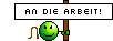 The twin should at least look similar to its brother. 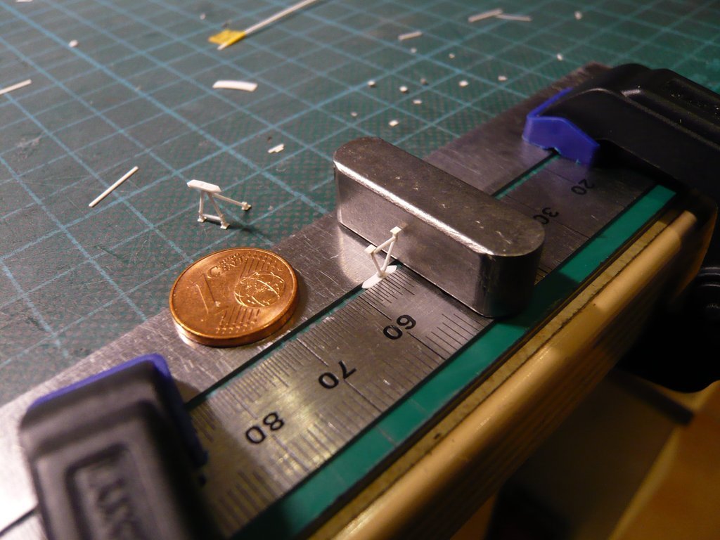 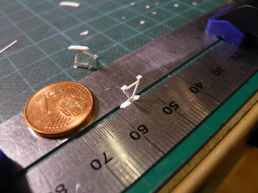 Only the Vertical Support Strut has to point to the other side, which I took into account in good time.  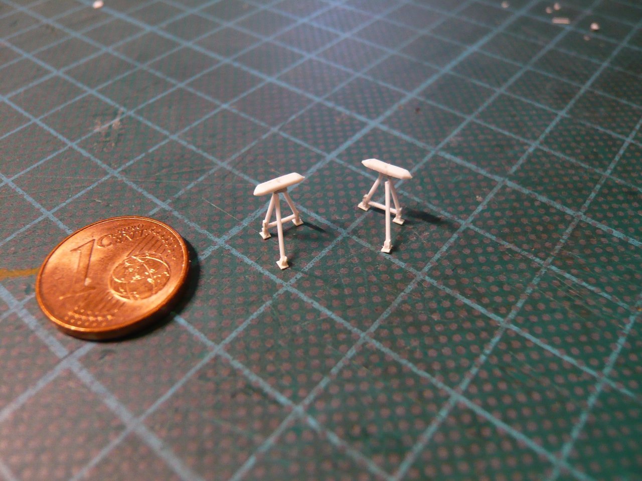 The way they both are standing there now, I think I've done quite well with them. 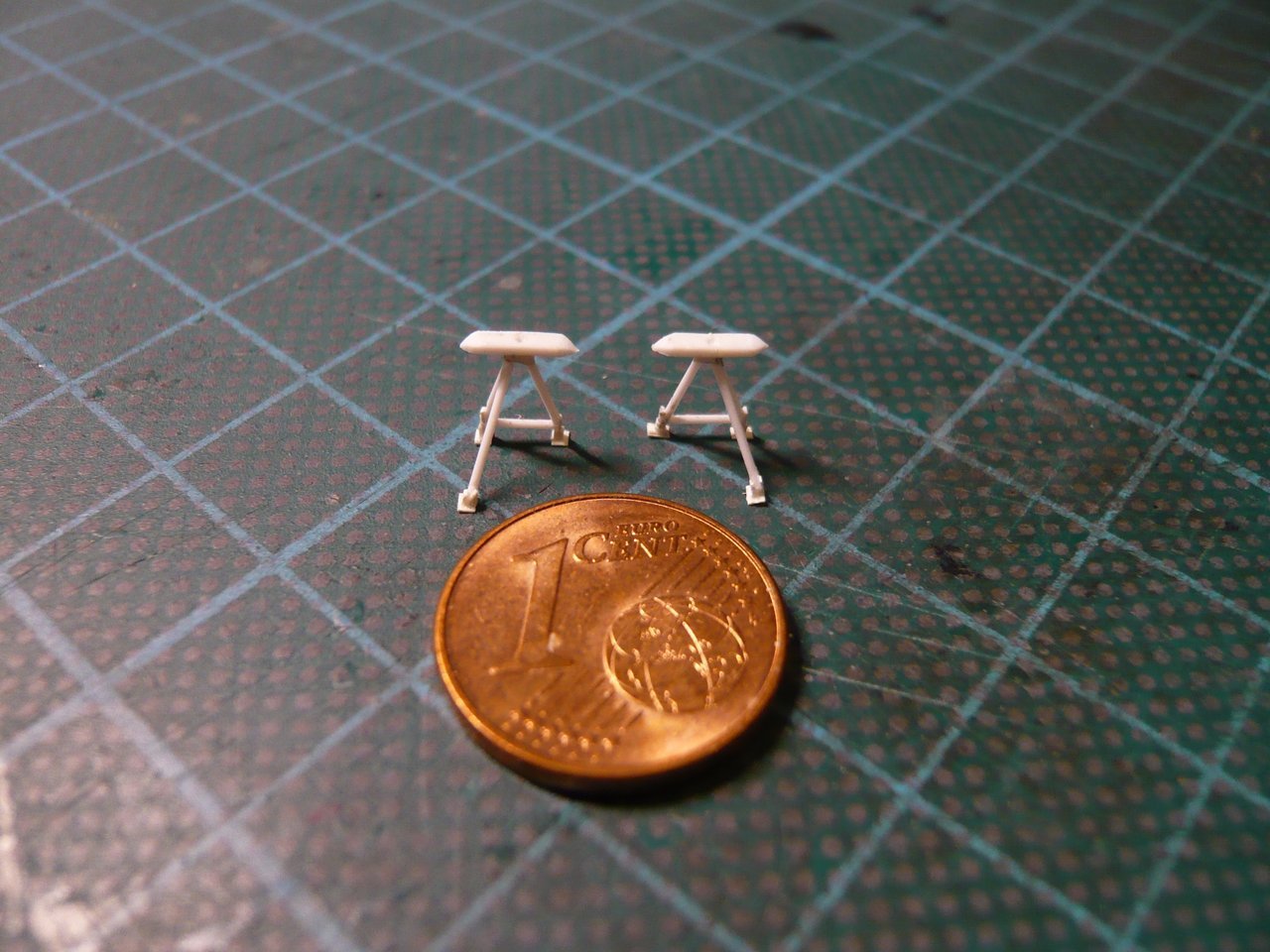 And here is the test fitting on the Starboard Side. 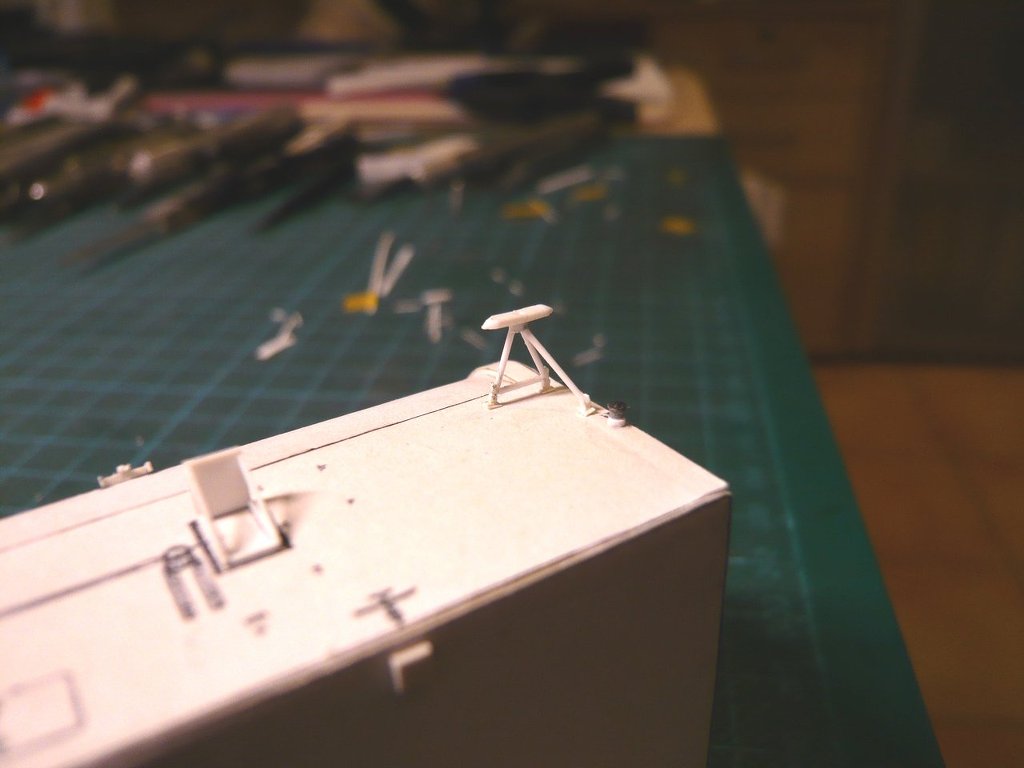 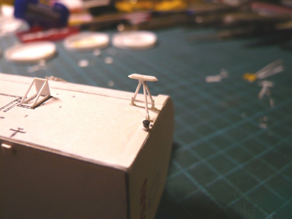 Next I'll probably turn to these Railings on the Forward Bulkhead of the canister, Source: forum.nasaspaceflight.com (STS-9, Ares67) which can also be folded in or out.
__________________
Greetings from Germany Manfred Under construction: Launch Pad 39A with Challenger STS-6 (1:144)
|
|
#2776
03-08-2023, 07:34 AM
|
||||
|
||||
|
Hello everybody,
first of all, I determined the dimensions of the eight railings (1:160) from the photo, which again was tiresome measuring and converting measures. In this the opposite Railings G-1 to G-4 have identical dimensions, which makes the work a little easier. 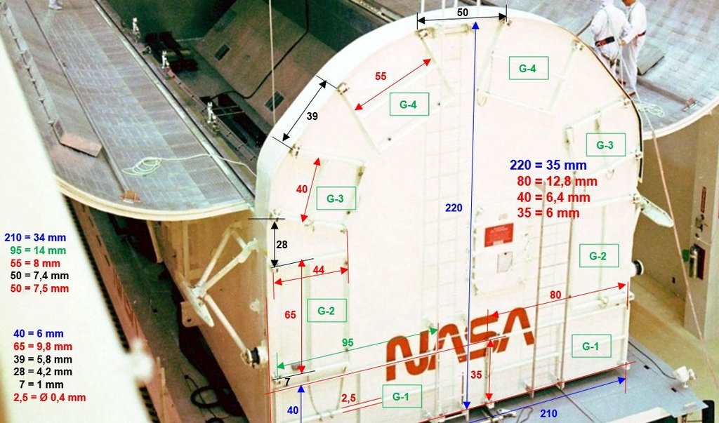 Source: forum.nasaspaceflight.com (STS-9, Ares67) Using this I've copied appropriately scaled rectangles into this NASA drawing (1:160), 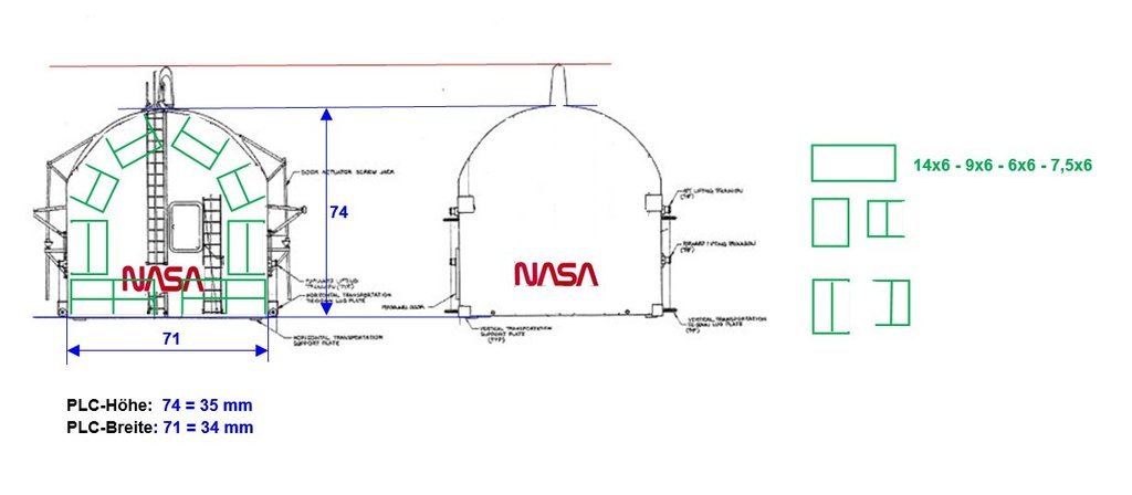 which I've printed out and can use as a template for scratching the railings. 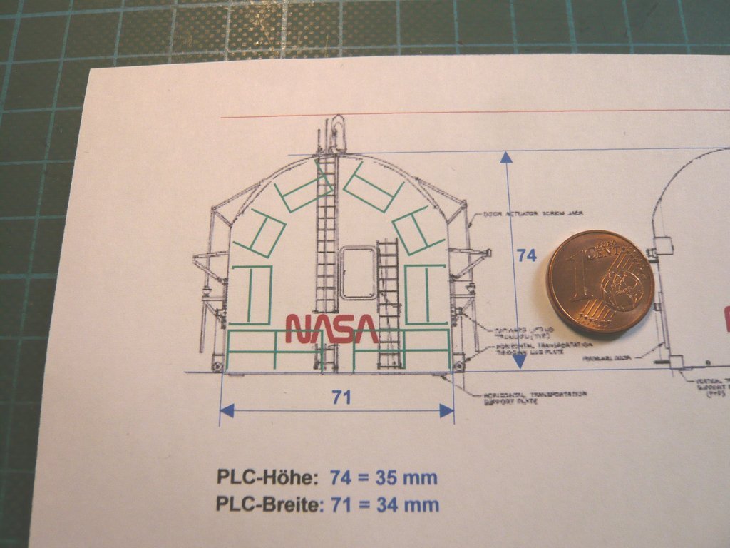 Now I'm going to look for the appropriate round rods (Ø 0,45 mm), and then I can start with the stressful cutting of the railing rods.
__________________
Greetings from Germany Manfred Under construction: Launch Pad 39A with Challenger STS-6 (1:144)
|
|
#2777
03-09-2023, 01:37 PM
|
||||
|
||||
|
Hello everybody,
first of all, here is a photo from the early years of the Shuttle Program (1980), on which the erected Railings can be seen, so that nothing could happen to the Can Crew guys when installing the Payload into the Payload Changeout Room (PCR). 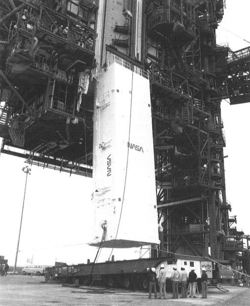 Source: Library of Congress, HAER FL-8-11-I And with this to the two lower Railings G-1, whose six individual parts I've cut out of round rods (Ø 0,45 mm). First of all, I thought about how best to assemble the railing and in which order I should glue the individual struts together. Doing it I then came to the division in the true-to-scale sketch with the corresponding lengths of the rods and decided on the variant with three Vertical struts (2, 3, 4) decided,  which ensures a better stability than the variant with two Cross struts (1). which ensures a better stability than the variant with two Cross struts (1). Since the vertical struts have the same length (5,5 mm) on all railings, I have cut 18 sticks for all eight railings using the Cutter chisel at the ruler stop. 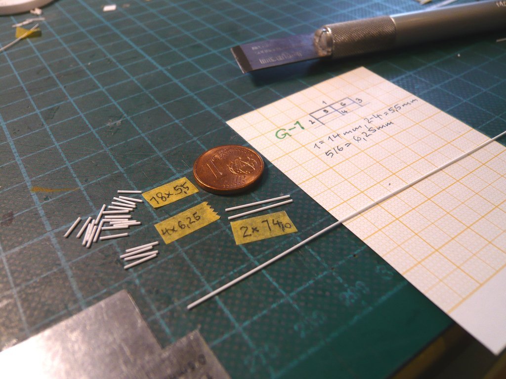 This was followed by the gradual gluing of the struts building the railing, for which I again used my tried and tested Clamping technique with the steel angle and the rulers. Due to the minimal contact surfaces between the struts, the adhesive application must be dosed carefully in order to avoid unsightly bonding with the base. 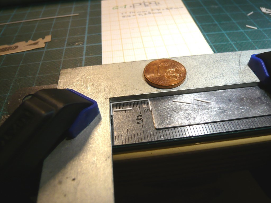 In order to get halfway to the same distances between the struts, I have prepared suitable spacers, which have proven to be very helpful. 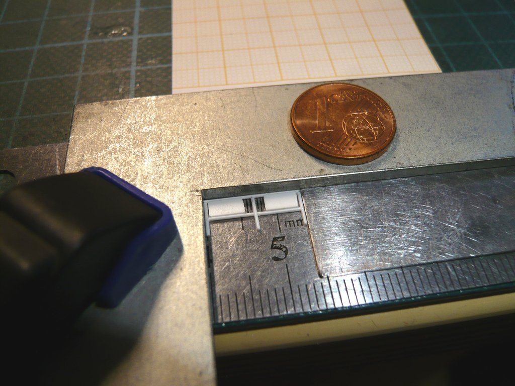 And this is what the first finished railing looks like, 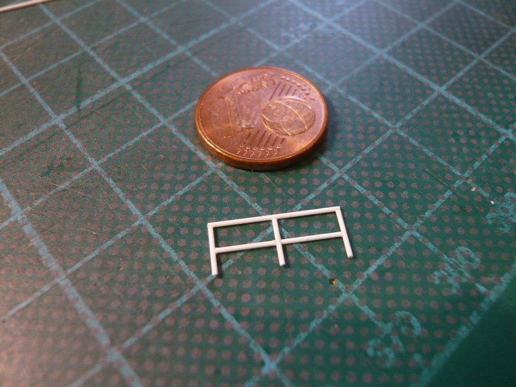 which fits perfectly on the template 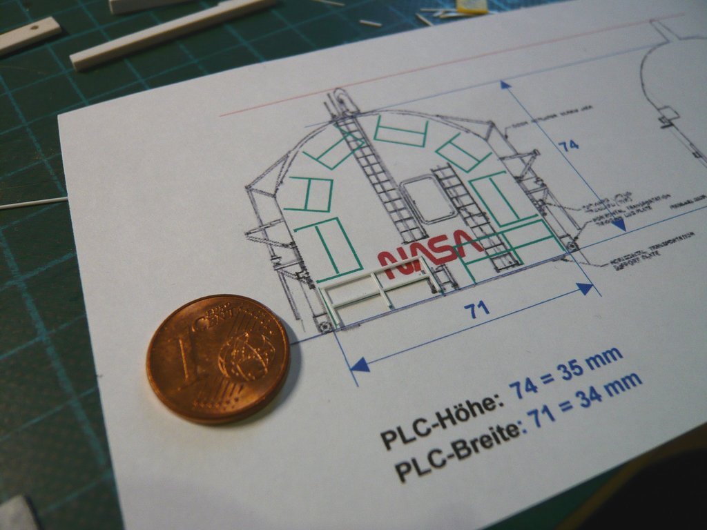 and also goes well with the canister. 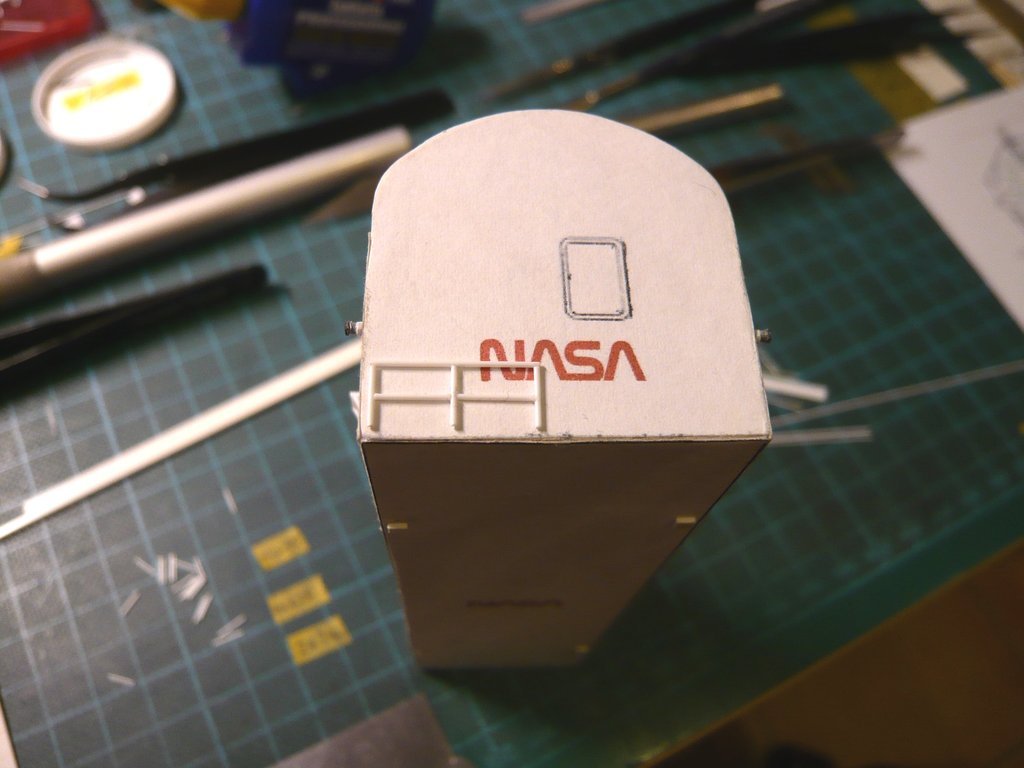 I wanted to take advantage of the fresh routine and immediately scratched the second Railing (G-1), 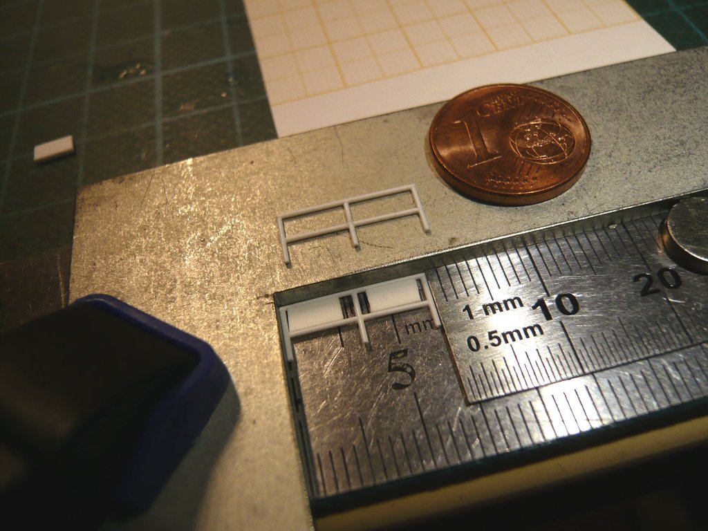 which has worked just as well. 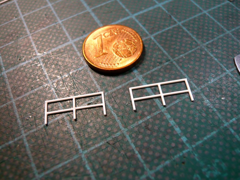 However, all railings still need on their feet similar Holders as those on the Outriggers so that they can be erected and swung in as required.
__________________
Greetings from Germany Manfred Under construction: Launch Pad 39A with Challenger STS-6 (1:144)
|
|
#2778
03-09-2023, 05:28 PM
|
||||
|
||||
|
Hello everybody,
but since I want to stay in the exercise, I'll scratch the remaining Railings first. Then it's the turn of the holder brackets. Since the side struts are already cut off, these are the prepared struts for the two Railings G-2, 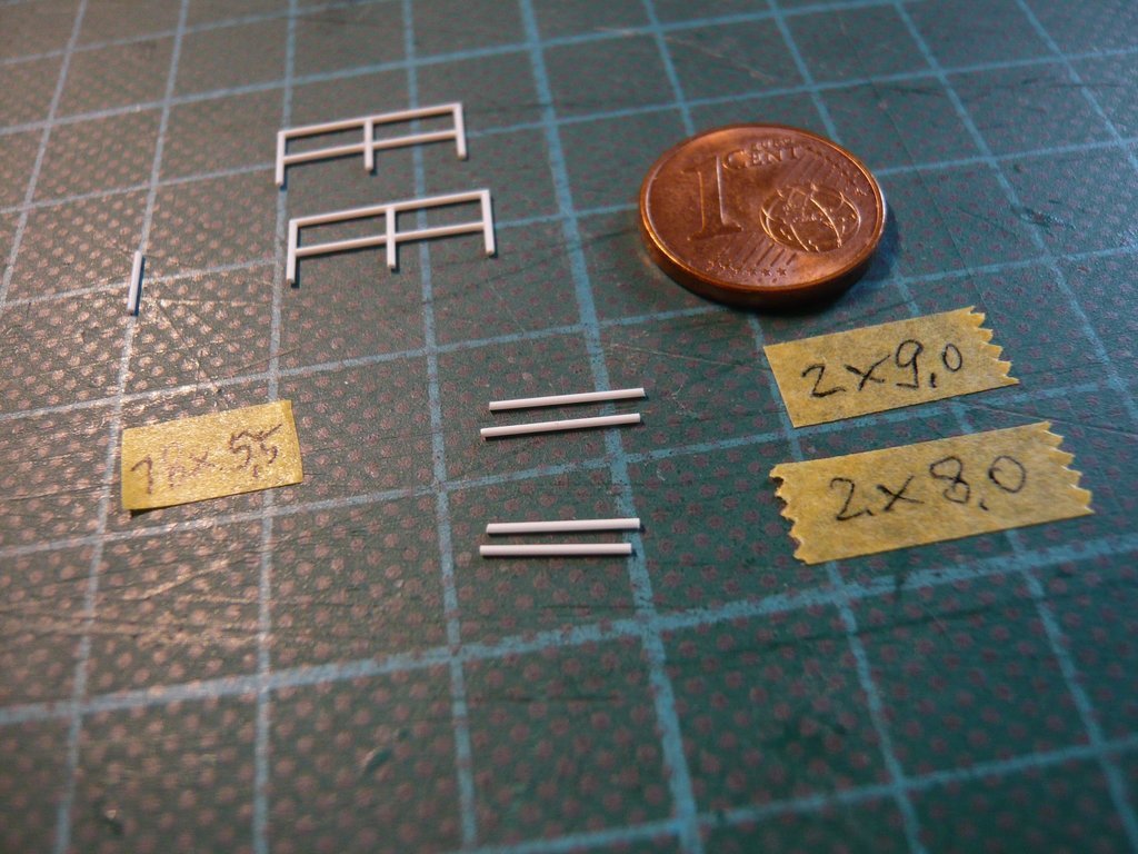 which were glued in the same manner. 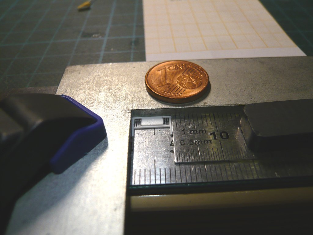 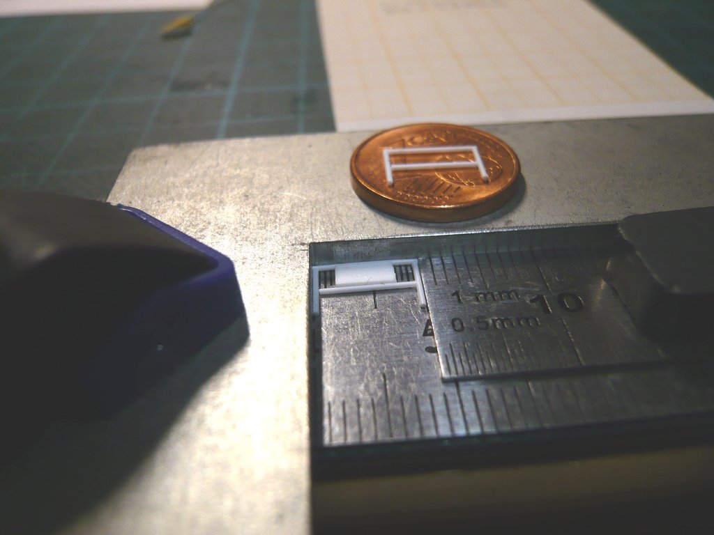 And now the remaining Railings G-3 and G-4 can follow. 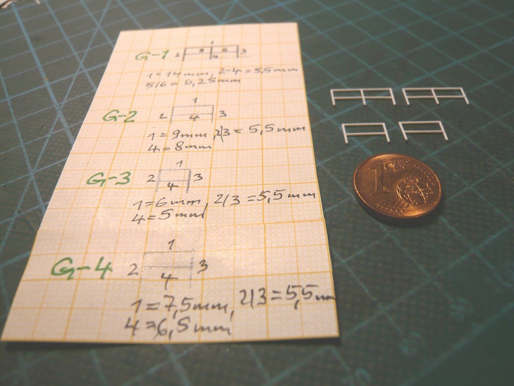 Once you know how to do it and the dimensions are known, it's nearly child's play.
__________________
Greetings from Germany Manfred Under construction: Launch Pad 39A with Challenger STS-6 (1:144)
|
|
#2779
03-10-2023, 12:56 PM
|
|||
|
|||
|
Hi Manfred. As you'd mentioned, a lot of care needs to be taken when gluing up the posts and rails on fences like these. I have been challenged in my modeling by this too and would love to have a better understanding of your approach to glue application.
Is it as simple as UHU CA glue on a wire loop applicator? Do you use an accelerator? Do you have any trouble with the glue adhering to steel ruler backing you are using? SO great to have you documenting this on the multiple forums! Thank you again.
__________________
Happy Crafting - Scot On the Bench: Planck and Hershcel
|
|
#2780
03-11-2023, 12:59 AM
|
||||
|
||||
|
Your whole project is incredible.
I am a great fan of the tiny details and miniaturization myself but in the terms of patience, neatness and accuracy you achieved really level 100!
__________________
Andrew aka Viator
|
 |
|
|


 Linear Mode

