


|
|
|
#51
 08-12-2013, 04:43 AM
|
||||
|
||||
|
Here is the next update with the six MMI's after painting. Those look here somewhat dark in the picture, are however brighter in reality, as one will directly see.
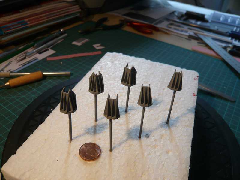 Here are the two corner interfaces at the Side 1 after the assembly. 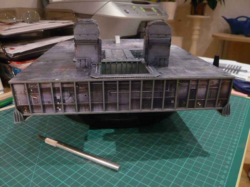 and here the MMI's to the other MLP sides.   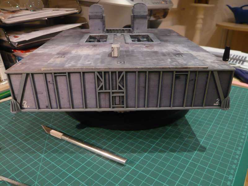 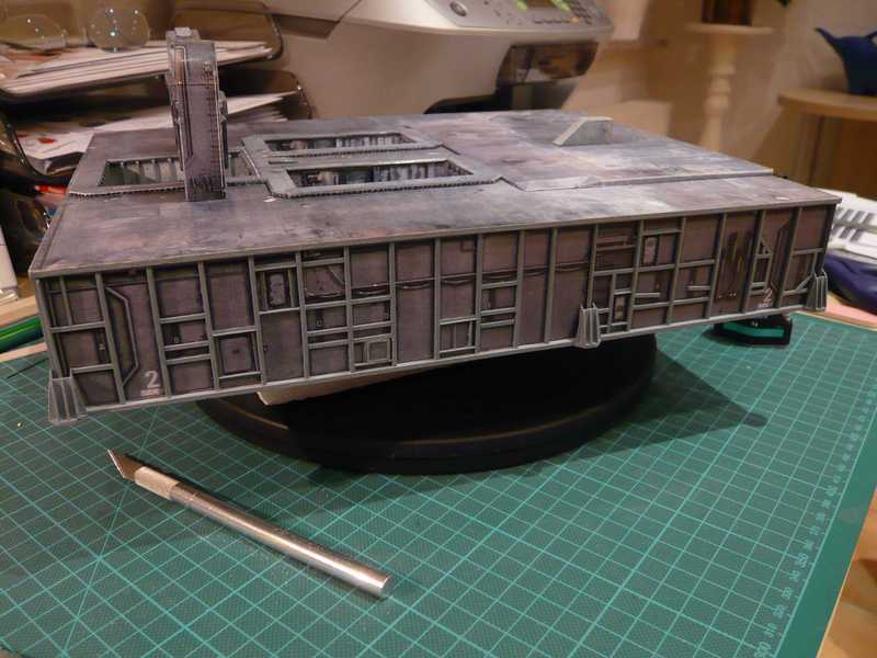 Without large break equal still with the four Access Platforms for the Side 1. Before painting the platforms were cleaned in an isopropanol bath thoroughly with the brush and dried afterwards with a blow-dryer. And in such a way the platforms look now finished painted from above, 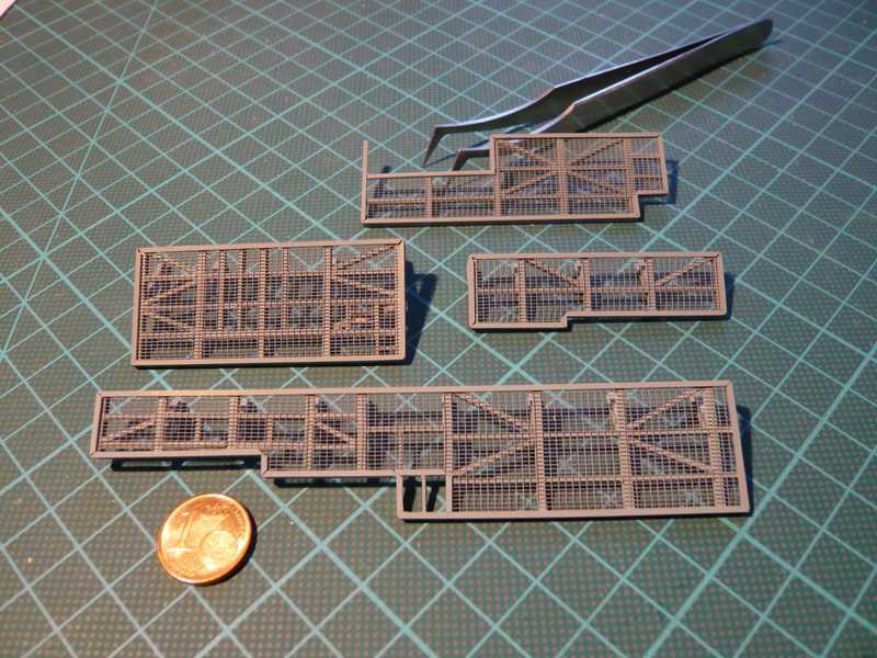 and so at the bottom 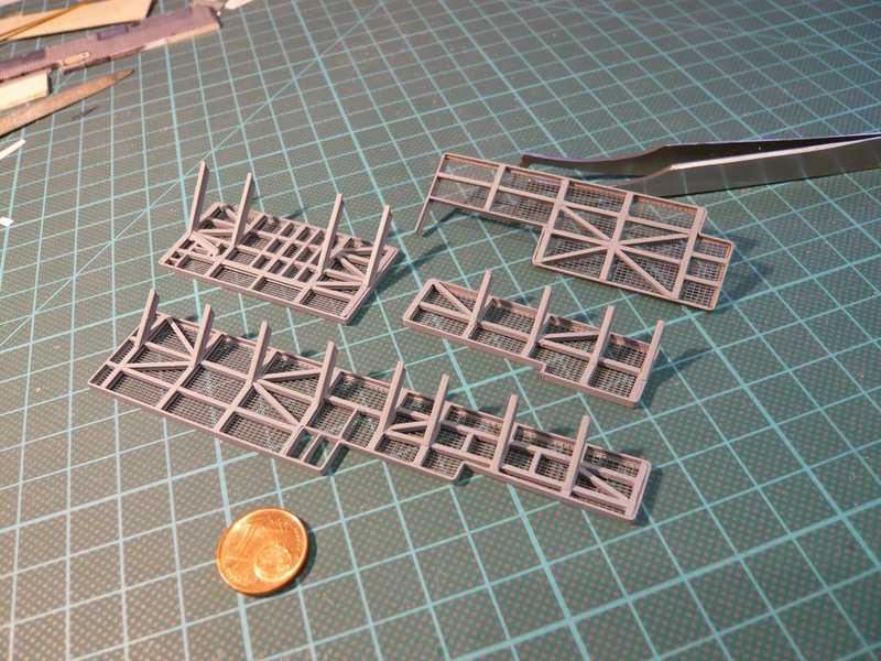 Next time the assembly can follow. 
__________________
Greetings from Germany Manfred Under construction: Launch Pad 39A with Challenger STS-6 (1:144) Last edited by spacerunner; 10-11-2016 at 06:57 AM. 
|
|
#52
08-13-2013, 01:20 AM
|
||||
|
||||
|
Here is the next update with the six MMI's after painting. Those look here somewhat dark in the picture, are however brighter in reality, as one will directly see.
Here are the two corner interfaces at the Side 1 after the assembly. and here the MMI's to the other MLP sides. Without large break equal still with the four Access Platforms for the Side 1. Before painting the platforms were cleaned in an isopropanol bath thoroughly with the brush and dried afterwards with a blow-dryer. And in such a way the platforms look now finished painted from above, and so at the bottom 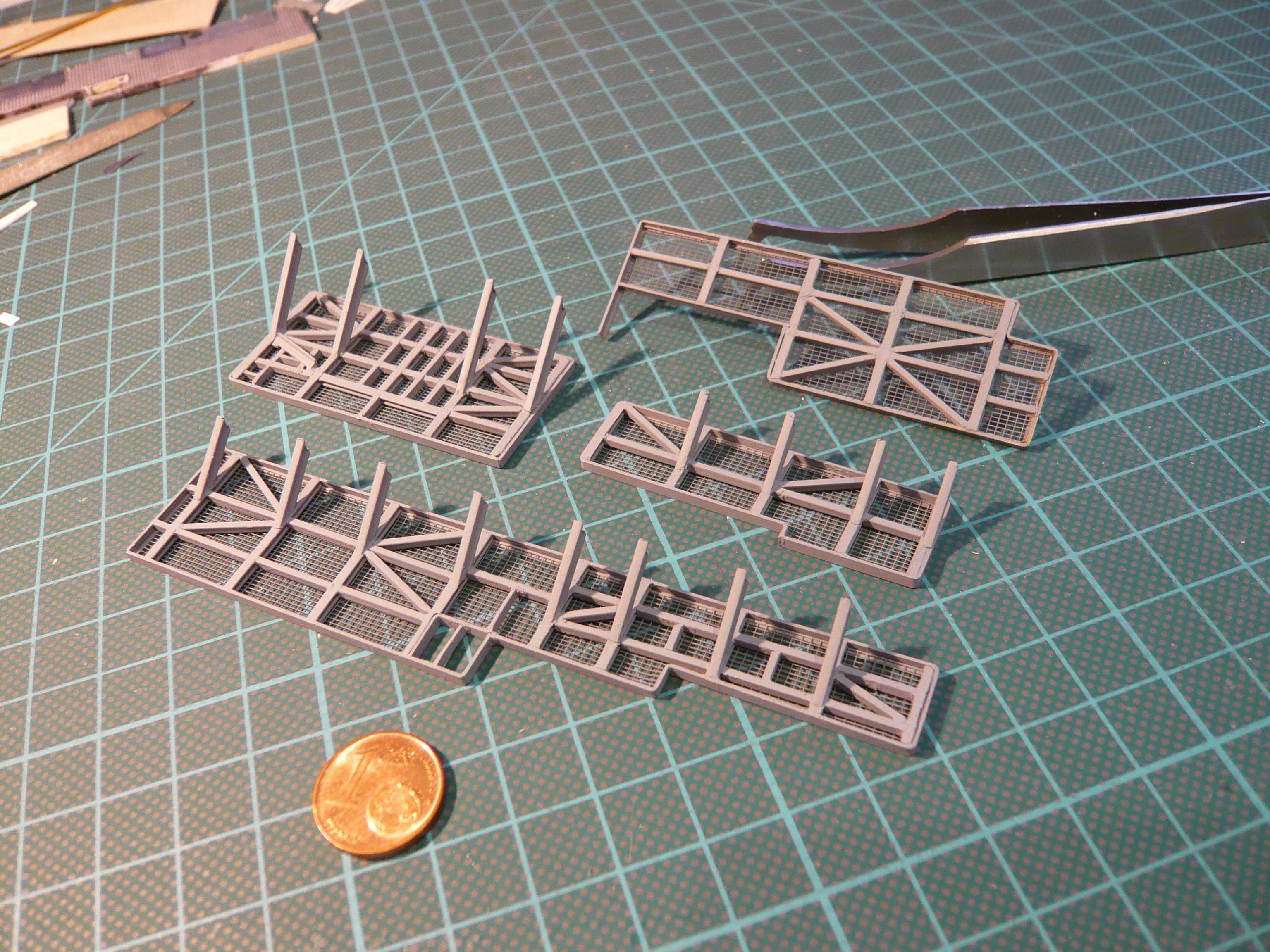 Next time the assembly can follow.
__________________
Greetings from Germany Manfred Under construction: Launch Pad 39A with Challenger STS-6 (1:144)
|
|
#53
08-13-2013, 01:30 AM
|
||||
|
||||
|
But befor the assembly of the Access Platforms follows, here are still some other details.
At the MLP buttom side there are these two small air grids above the Crawler's cab, which should not naturally be missing. 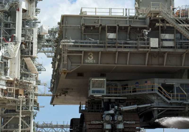 Source: NASA Because those are rather tiny, I used the fine-meshed ribbon for the lattices again. Among them the prepared frameworks with the black background already lie. 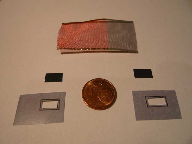 Next the lattices were glued behind the frameworks, cut out these then and glued afterwards on the black background, that already were it. 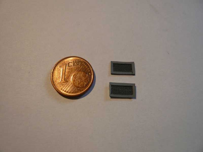 And in this photo the air grids are already installed. 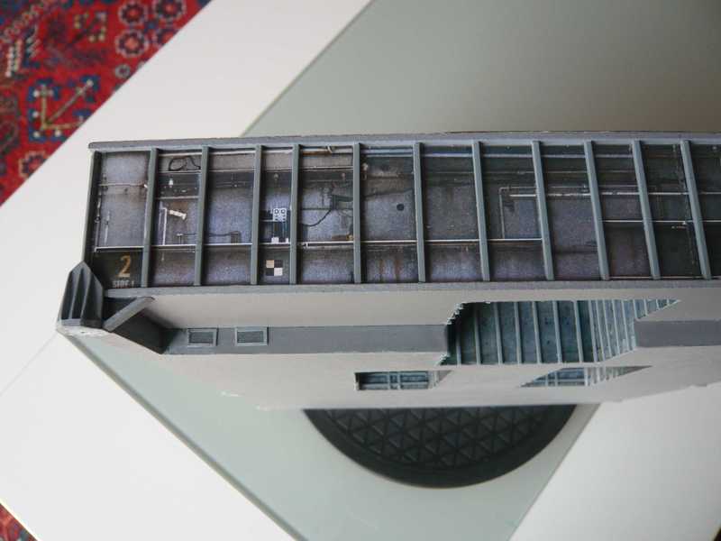 Next the bottom plates of the MMI's (from the AXM template) were glued together and then the holes for the centering bolts were carefully bored (Ø 2.4 mm). 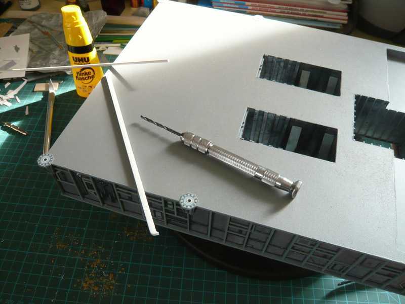 Subsequently, below the Side 4 the three markings for the SSWS pipings and in the center four markings for the Crawler Transporter/MLP Mechanical Interfaces were attached. 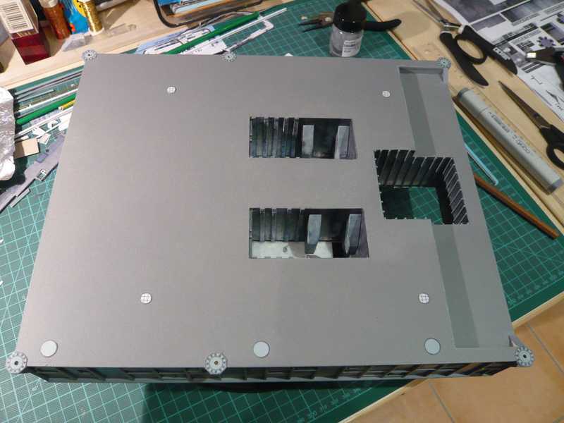 Those are the four support points of the MLP on the Crawler, which has in each case a distance from 27,40 m from each other, as one can see from this picture from David Maier's Crawler building guidance. 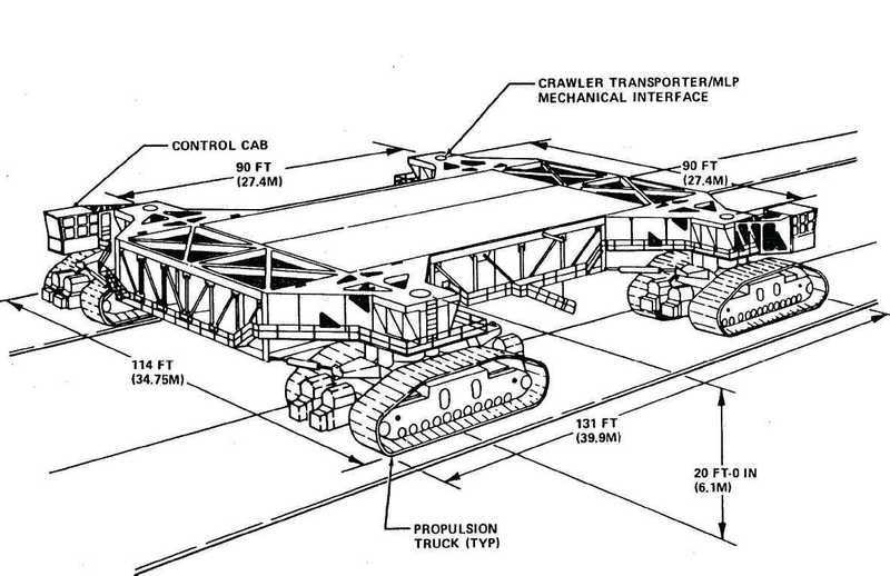 Source: EDU-Craft Diversions(CD-ROM) In the end the centering bolts already painted (Ø 2.3 mm) were then glued into the drillings, with which the buttom side is complete now. 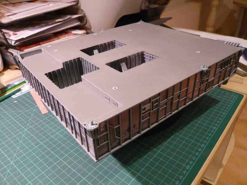 And now the welding operators have begun with the assembly of the Access Platforms, and like it itself belonged, naturally with the Access Platform AP 1. That is the largest of the four Access platforms here at the left front. 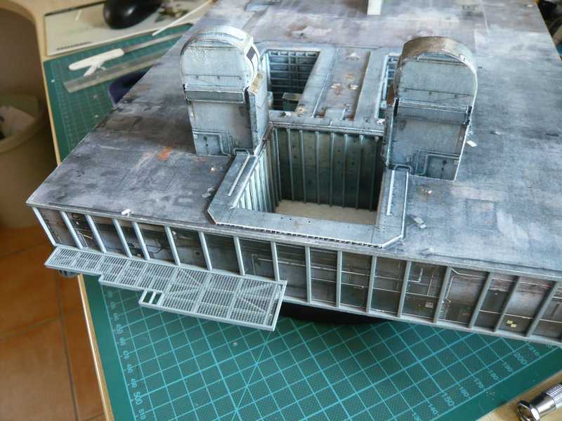 On this platform there are some parts of the LOX Valve Skid, as well as filters and armatures, how one can see in this picture. To the protection from hot exhaust gases during starting these platforms are roofed over through Blast Shields. 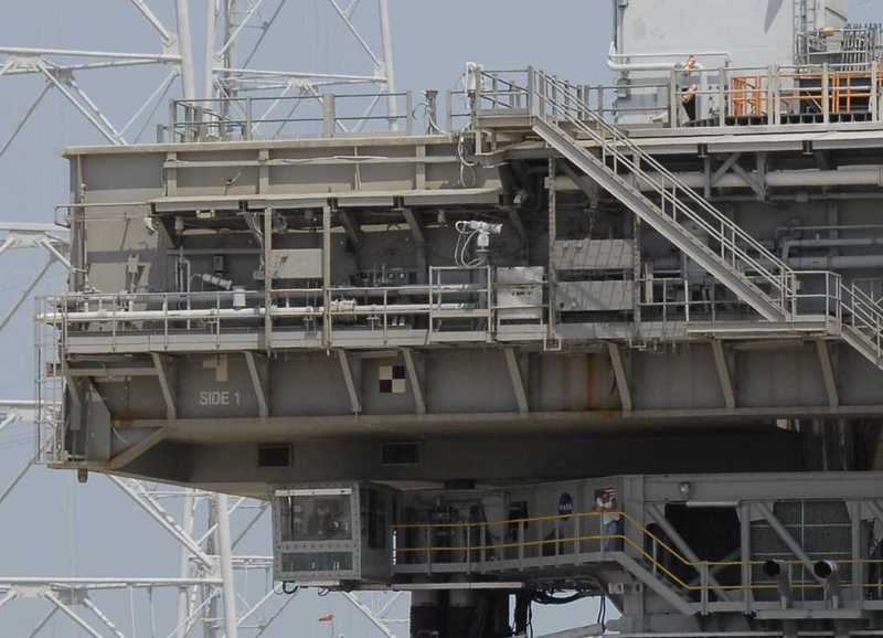 Source: NASA The associated parts in the used Paper kit look in such a way: 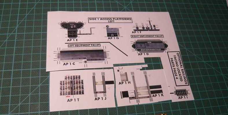 There are two Equipment Pallets AP 1 C (left) and AP 1 D (right) with some armatures, as well as two panel retaining structures AP 1 J and AP 1 K, which however can be attached only after the assembly of the Blast Shields. I have put the pallets here provisionally on the platform. 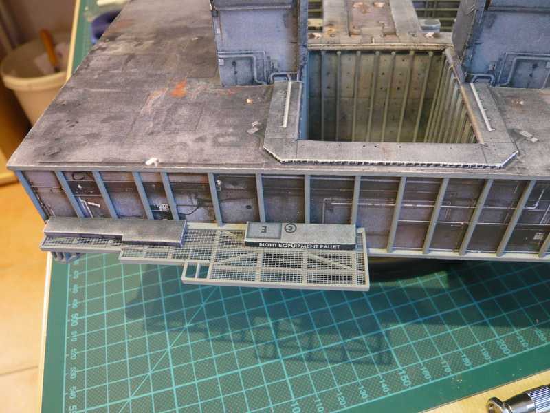 In reality the right pallet is however no closed platform but a framework from H-Beams, as one can see here in the following picture of the right pallet with the LOX Filter in the center.  Source: NASA Therefore I'll scratch build these pallets from plastic profiles.  So long!
__________________
Greetings from Germany Manfred Under construction: Launch Pad 39A with Challenger STS-6 (1:144) Last edited by spacerunner; 10-11-2016 at 06:58 AM.
|
|
#54
08-13-2013, 01:26 PM
|
||||
|
||||
|
Thus I will scratch-build the right pallet from H-Beams (1,5x1,5 mm), in order to remain closer at the original. With the left pallet (AP 1 C) it looks somewhat differently.
And here is my first attempt with parts of the paper kit, in order to show the difference to the original better, so that you can judge. 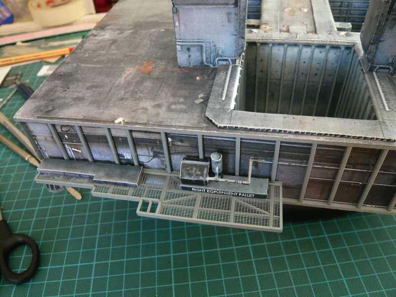 Here the first armatures are to be seen on the right pallet, on the left the "Black Box" with a piping to the right in the back and behind it the LOX Filter. The box as such does not exist in such a way in the original. Those are here again only hazy suggestions of the pipings left from the LOX Filter, if you want to compare with the last picture. And now still another further detail is added. 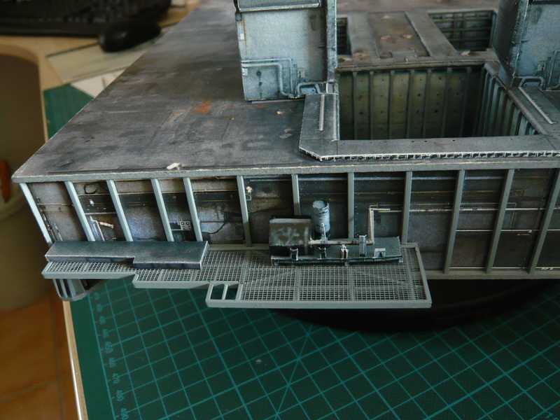 That should be the mounting plates of different pipings which there stand in front of it. The more I look at myself against the original photographs, the less I am convinced of the paper details, particularly since it looks really differently in the original MLP. I mean also that the H-Beams framework is some more longer and extends to the left, probably up to the end of this Bay with the inlet of the white LH2 Pipe into the MLP wall, which leads then to the TSM. One can recognize the inlet as black point left above the box. It seems to me that I must think about it still more exactly.  And here is a update to the Access Platforms, which are now completely installed.  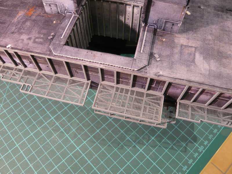 Between the AP 2 and AP 3 the first supports were drawn in. 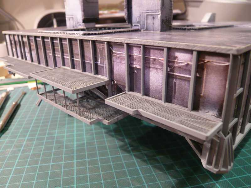 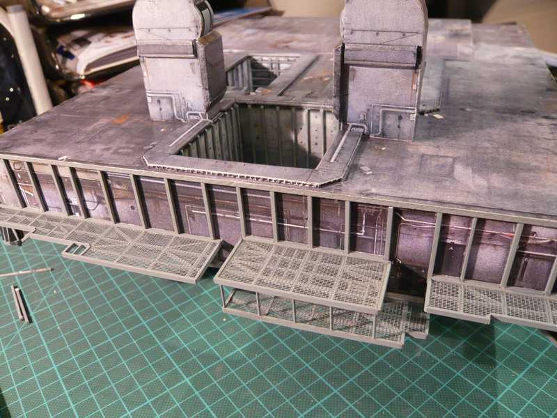 And then still completely surprisingly the stair builder went past and already took measure. 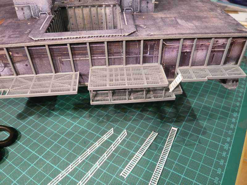 So it can go further. That would have been also too beautiful, but thus the safety check agreed unfortunately not at all, which was turned up suddenly and for the surprise of all and concerning the platforms gave some editions, which are shown by the following picture: 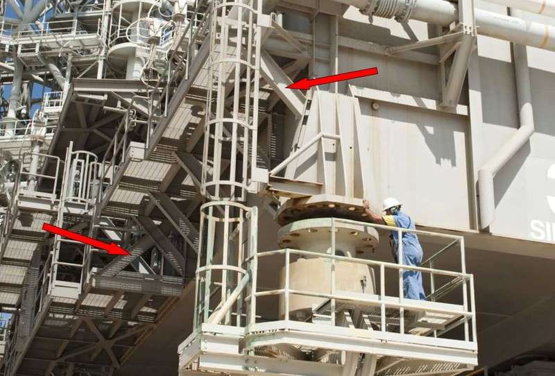 Source: NASA The inspection did not only have complained the missing platform bracer over the corner MMI interface (right arrow) , which was in the meantime already improved. Above all however it was criticized that between the lower platform AP 2 and the outside AP 4 a stabilization prop (left arrow, I-Beam) is missing, which must be absolutely still attached, before the final inspection can take place!  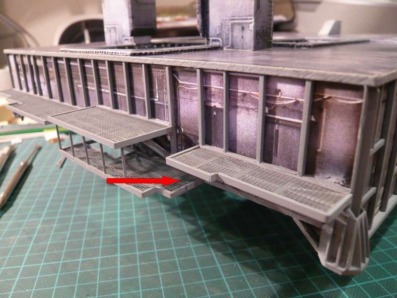 But those inspectors are right, safety first!!! And therefore the welders drew in the complained of missing props also fast, as one can see here. :  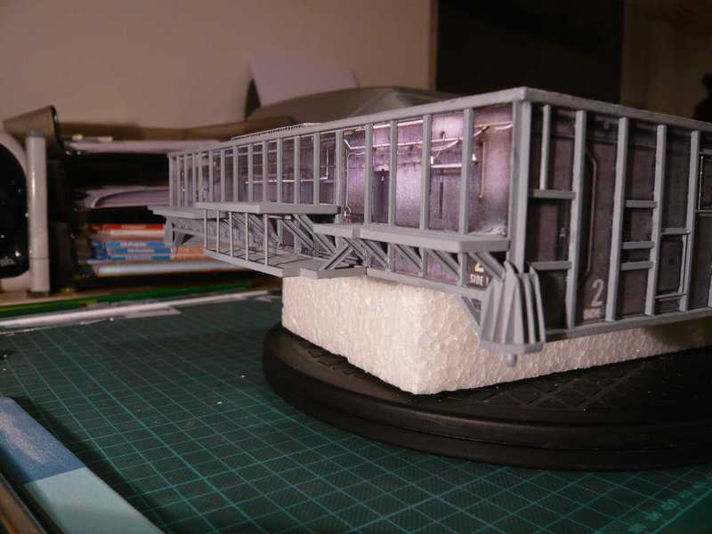 And now finally all are content.
__________________
Greetings from Germany Manfred Under construction: Launch Pad 39A with Challenger STS-6 (1:144) Last edited by spacerunner; 10-11-2016 at 06:59 AM.
|
|
#55
08-13-2013, 01:39 PM
|
||||
|
||||
|
Amazing!
Manfred,
As a baseball fan might say.......You hit this one out of the park!!! Love your work .... Bill
__________________
----------------------------------------------- Seems to have been Deliberately Buried ----------------------------------------------- Where did Gunter Wendt ? 
|
| Google Adsense |
|
#56
08-14-2013, 01:51 AM
|
||||
|
||||
|
Thanks Bill for your nice words.
 And so that again back on the Access Platform AP 1, where I had already begun with the two pallets from D. Maiers Paper kit, which did not so completely convince me however. And therefore I assiduously scanned archives again for detail photographs. As one can recognize in the following picture from below the left Equipment Pallet, this pallet is a closed frame construction with a coverage. 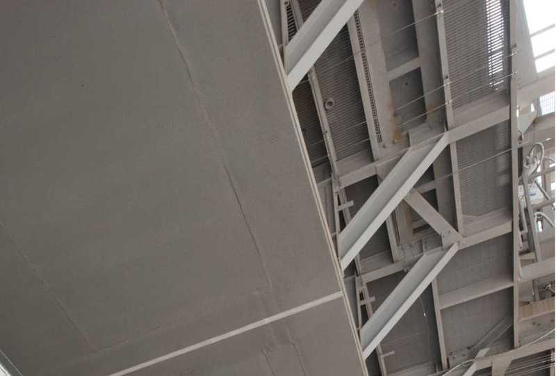 Source: NASA At least the middle range (without gratings) is closed upward and one can even recognize some girders. From the same photo series there is a further picture from something other position. And on that one can recognize the following details with experienced view, and eagle eyes. 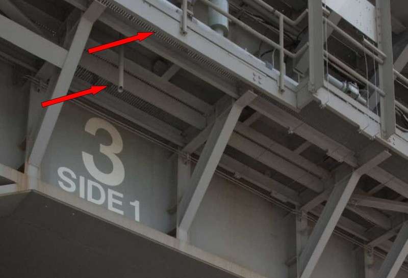 Source: NASA In the ranges marked by arrows actually light from above shines through. That would mean that only the middle closed part belonges to the left pallet which has a coverage. In D. Maiers Kit the left pallet is closed, but sits however directly before the MLP wall. And I assume strongly that it has also no break as with D. Maiers kit, but continuous exhibits the same width. In the meantime I investigated also in NSF forum and found thereby these two detail photos of the left pallet, which seems to confirm my theory. In the first picture one sees the framework of the pallet behind the grating strip with pipes and armatures of the LOX Valve Skid. 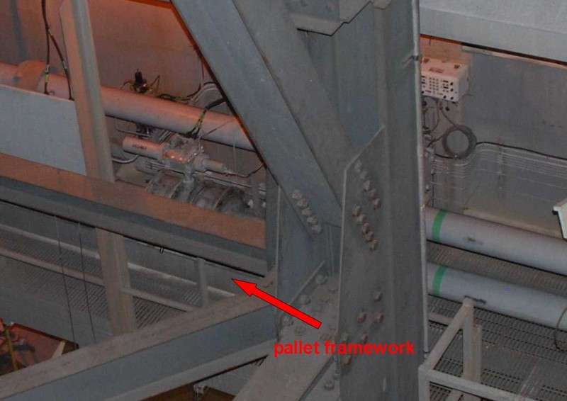 Source: NASASpaceflight.com (J. Patterson) And in the second picture of the same place one can recognize the rear grating strip in front of the MLP wall. 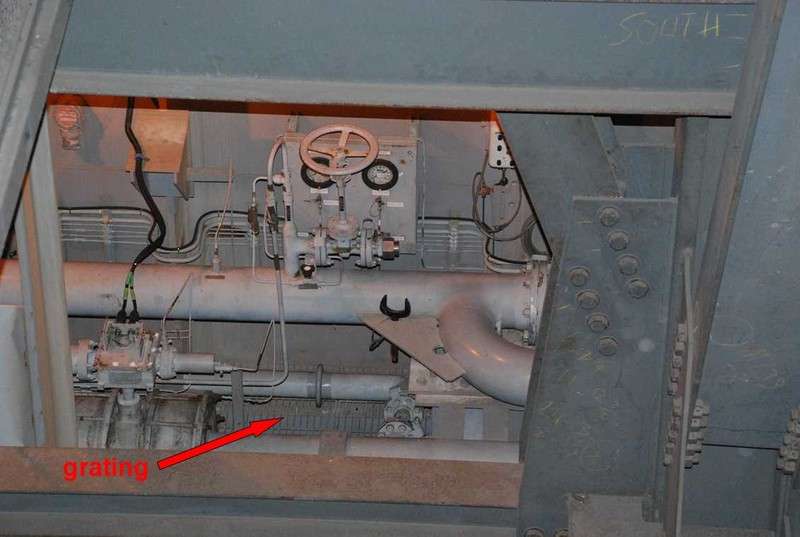 Source: NASASpaceflight.com (J. Patterson) After these questions are clarified now to the pallets on the Access Platform AP 1, finally far can be with the practical work on the right Pallet of the LOX Valve Skid, which is to be seen in this photo again beautifully. 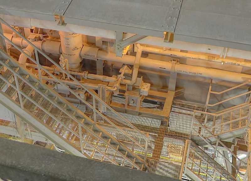 Source: NASA For the framework I essentially use H-beams 1,5x1,5 mm. 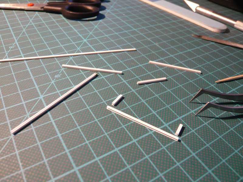 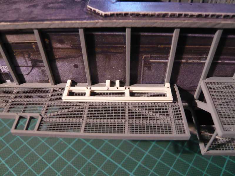 As one can see however in the previous NASA photo, the pallet sits not concisely on the grating, but stands for something increased on small bases. And those I'll build then tomorrow, together with further cross beams and bracers, up to the base frame for the LOX Filter. Therefore first times eight small bases came as feet under the right pallet from square profile 1,5x1,5 mm. 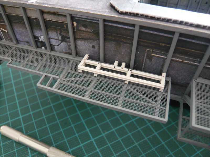 In the center the two small extensions indicate already the location of the LOX Filter. Then there are several cross beams on the framework, on which further mounting plates for pipings etc. sit, from which first is installed here already. The cross beam is H-profile 1.5x1.5 mm, the front prop from T-beam 1,5x1,5 mm. 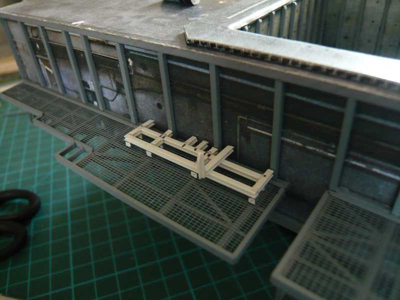 Further left there is still another second mounting plate of this kind, which is to be seen in the next picture. Then I have built the next miniature, that is the mounting plate right beside first with the T-beam, which has a special structure, which I had to look at myself and then consider only longer time, from which I can make it best. For the base frame I finally took then after some preliminary tests failed a H-beam 3.0x3.0 mm and on it still few small parts from sheet glued. 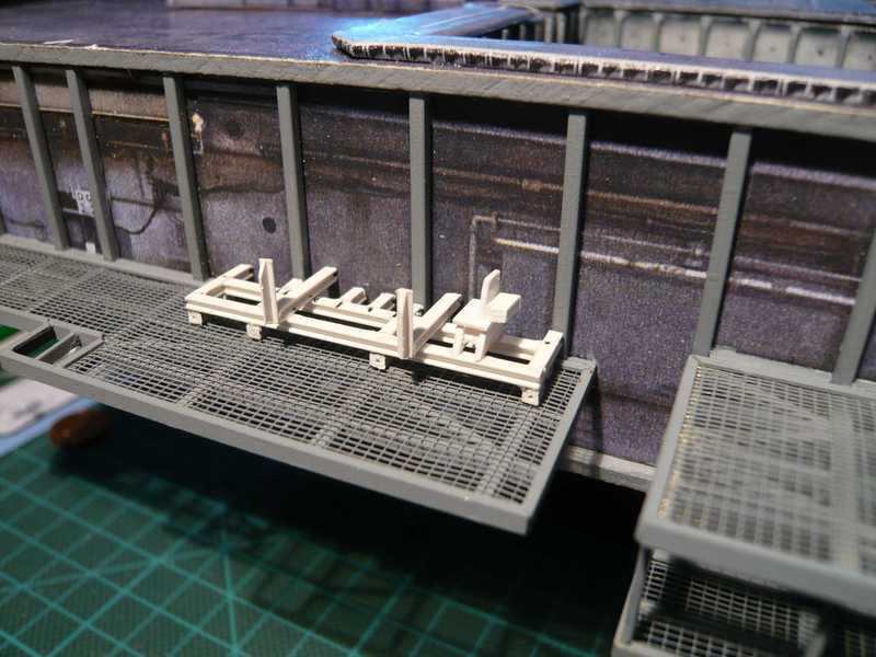 And I must say, these details stop genuinly and require already some at patience and concentration. Up to now about 25 component parts are in the pallet, and those are not yet all, if you look back to the NASA photo. Well yes, I wanted it in such a way, now I thereby began, and now I'm also keep on doing. I think already that the expenditure will be worthwhile itself ... 
__________________
Greetings from Germany Manfred Under construction: Launch Pad 39A with Challenger STS-6 (1:144) Last edited by spacerunner; 10-11-2016 at 07:01 AM.
|
|
#57
08-14-2013, 11:39 AM
|
|||
|
|||
|
My God, Manfred, this is superb! It's a joy seeing all of this come together. Greetings from Germany!
|
|
#58
08-15-2013, 12:22 AM
|
||||
|
||||
|
Thanks Revell-Fan for your nice compliments,
and Good Morning in Verden. There are still lots of to do, but I'm trying my best.
__________________
Greetings from Germany Manfred Under construction: Launch Pad 39A with Challenger STS-6 (1:144) Last edited by spacerunner; 10-11-2016 at 10:14 AM.
|
|
#59
08-15-2013, 12:30 AM
|
||||
|
||||
|
Before it continued to go to the left on the pallet, it however still gave another surprise by a new photo.
I had already stated that the right pallet in D. Maiers Paper Kit is somewhat too short. And on the basis of photos I've meant that it goes at least to something over half of the Bay 6 outside. In the meantime I know it more exactly. The pallet goes even up to the border between Bay 5 and 6, how one can see in this photo. 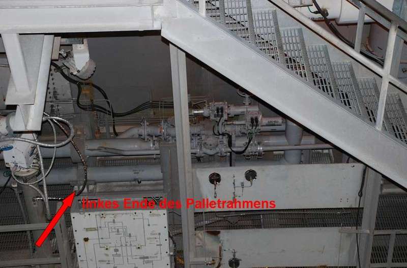 Source: NASASpaceflight.com (Jay Patterson) The arrow marks the left end of the right pallet framework. Keep in mind for orientation the foot of the camera to the left of the arrow, and if you then look at the next picture, you can see, where that is about on the platform. 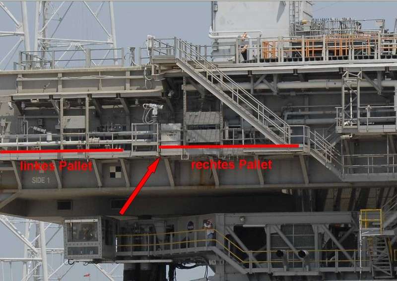 Source: NASA The right pallet is so long in reality, it reaches up to the arrow, and thus the pallet from D. Maiers Kit is approximately 1 cm, too short nevertheless! That means that I must extend my pallet framework still by the missing piece up to the border between Bay 5 and 6. Thus first times the pallet framework was extended on the left by the missing piece. Then were added still a few new details. For the LOX Filter a small platform was prepared from two small H-Beams and sheet, already the round profiles for the filter was ready put. Besides a further piping mounting plate lies. 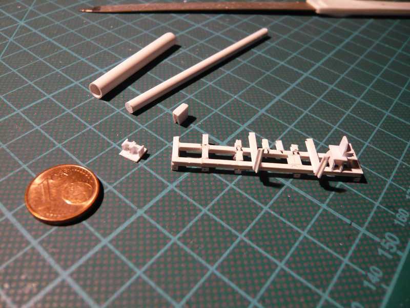 In the meantime I've noticed from pictures that there are obviously different designs of the LOX filter, depending on which MLP was used. With the MLP-2 the LOX filter sees in such a way from as in this picture with the STS-132:  Source: NASA The LOX line flows here directly into the filter part with the largest diameter. Differently it looks e.g. with the MLP-3 with the STS-124. There the filter has several diameter gradations, and the LOX pipe flows into the lower part with the smaller diameter. 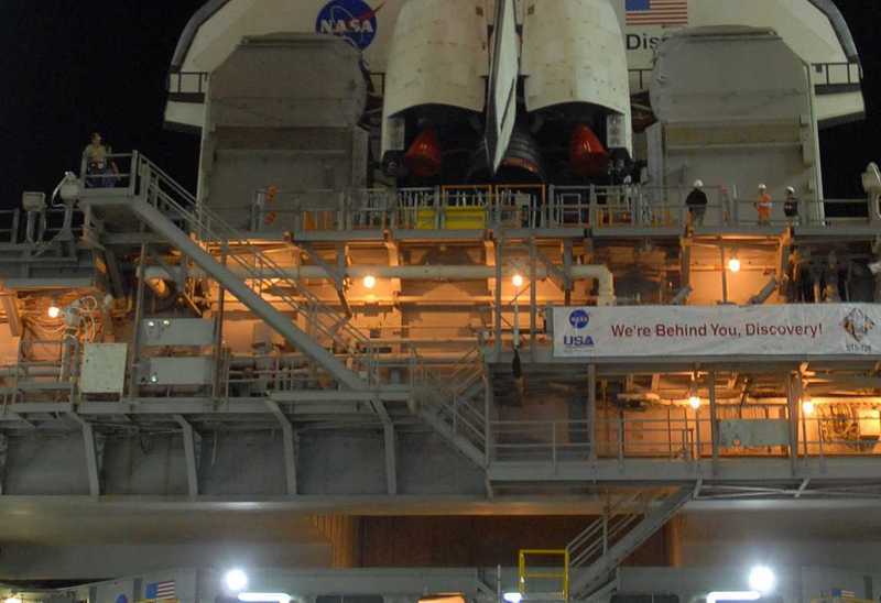 Source: NASA And here now still another photo with the new details on the right pallet: 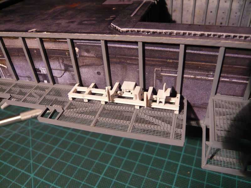 I followed to the thing with the different LOX filters again and therefore I looked at myself in particular older photos of the earlier Shuttle missions. And afterwards is it really like that: The two MLP's MLP-1 and MLP-2 have this filter, as it is to be seen on the panorama photo of the STS-132. And here to the confirmation is again an older picture of the STS-63 (1995), on which this type of filter on the MLP-2 is to be recognized well with High resolution (2x click). And with the STS-6 MLP-2 was likewise in the use with this LOX filter.  Source: NASA The MLP-3 against it had always the other filter design, as in the photo of the STS-124, which would be clarified thereby. Since I dedicate my project to the mission STS-6, with which the MLP-2 was in use, I therefore tried to scratch-build this type of LOX filter. Here are the parts necessary for it. Those are two different pipe diameters, which larger (5 mm) for the top, into which the LOX pipe flows, and a smaller part under it, which sit on the small platform, as well as a cover sheet. 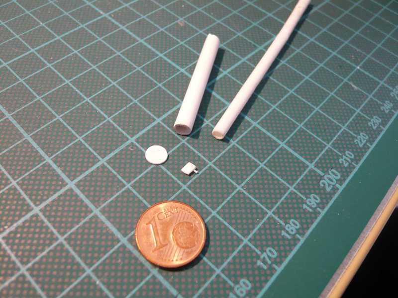 Beside the cover sheet lies a small board, which sits before the filter on the pallet framework. There one must look then later already exactly, in order to recognize it. And then the filter in the top has still a circulating nip, which I would like suggest as ring. In addition I used a thin wire (0.4 mm), which I preformed around the thicker filter pipe. 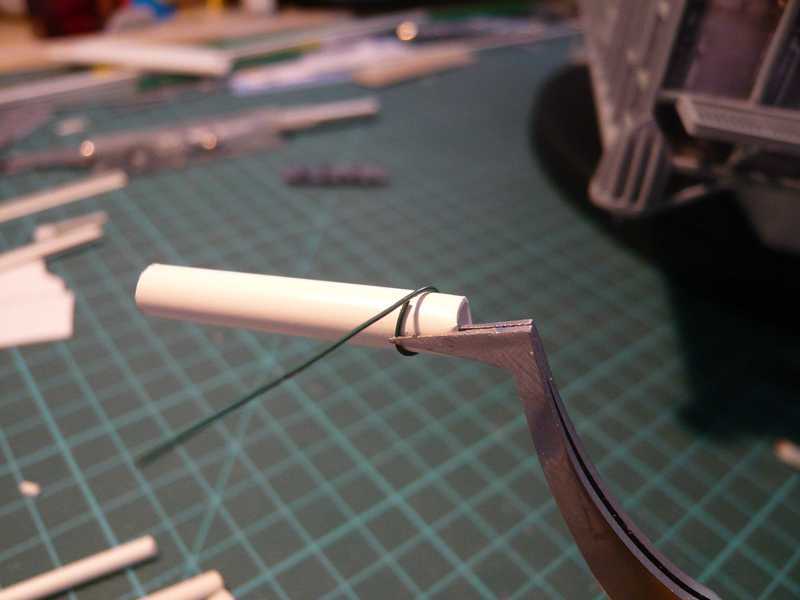 That can be glued now on the prefabricated filter with superglue. 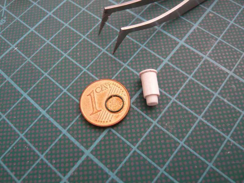 And that is now the finished LOX filter, and besides to the comparison again the filter from the Paper kit. With one by the way sees the small board mentioned above on the black underground. 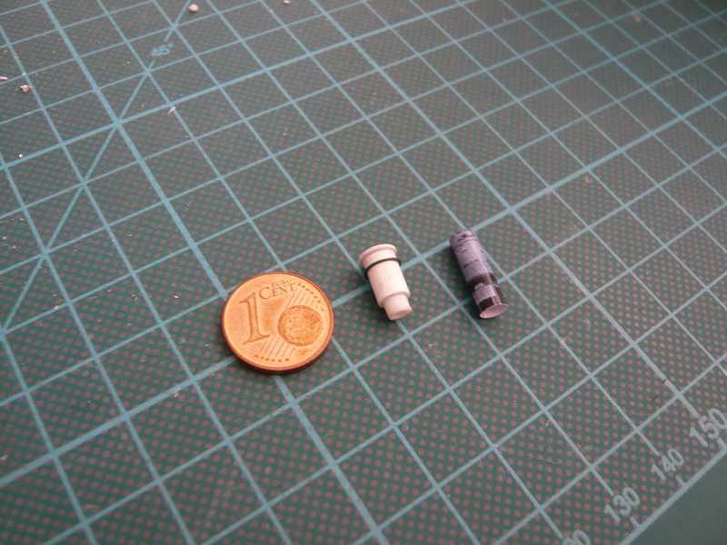 And that's now the fitting of the nearly finished right pallet, which could actually go now into the paint shop. A few small props in addition had still come. 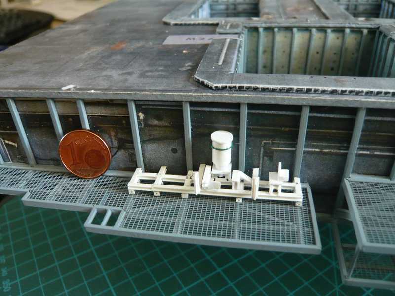 Now naturally still the thicker LOX and LH2 pipes as well as some thinner pipings, as well as mounting plates/clips, etc. are missing ... 
__________________
Greetings from Germany Manfred Under construction: Launch Pad 39A with Challenger STS-6 (1:144) Last edited by spacerunner; 10-11-2016 at 07:04 AM.
|
|
#60
08-16-2013, 12:29 AM
|
||||
|
||||
|
Hey all together,
it's time now to take next the LOX and LH2 pipes. This chapter will be probably a little more difficult. I want to proceed in such a way that I begin first on the Side 2 in order to see, how the two main pipes run around the corner to the Side 1, in order to manage the local binding well in particular those the LOX pipe, which leads inevitably by the LOX filter. Here in this picture one can see quite well, how the pipes run around the corner. 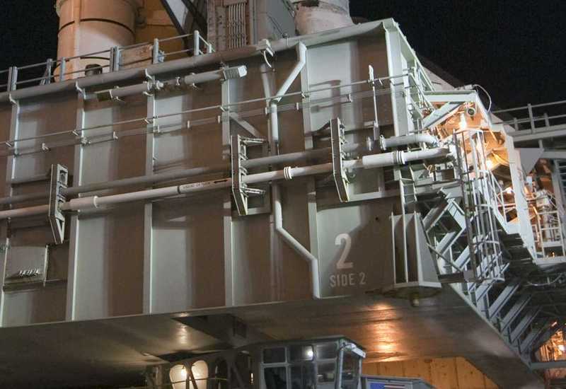 Source: NASA Let's have a look at the LOX-Pipes for Side 2. Those are here the pipes and Pipe Supports from the Paper kit, of which with however, honestly said, I have a horror.  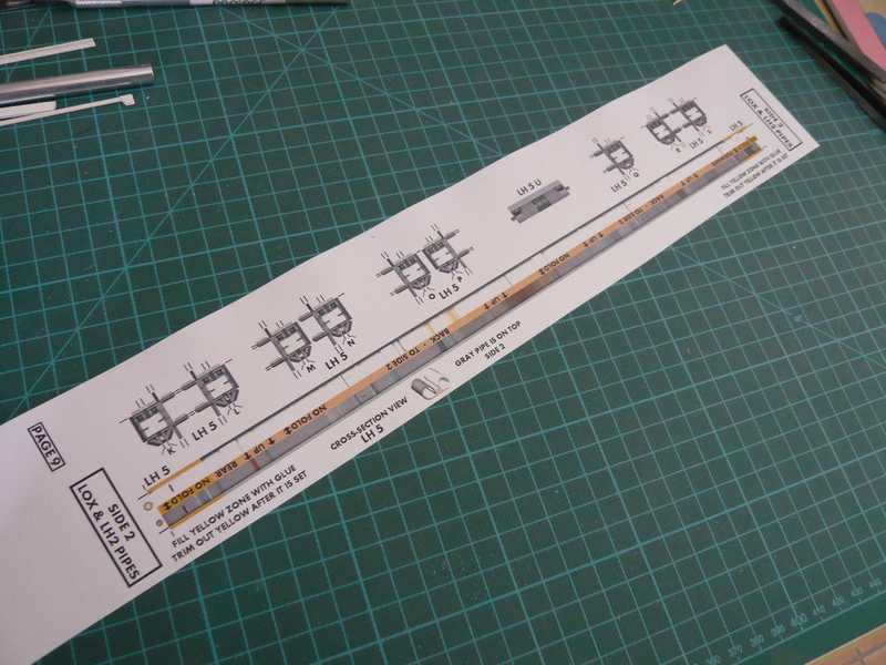 In particular if I look at myself and present in addition the handling layout in such a way in the following cross section to have to turn this “tube duo” together/into one another/against each other of paper, that frightens me!  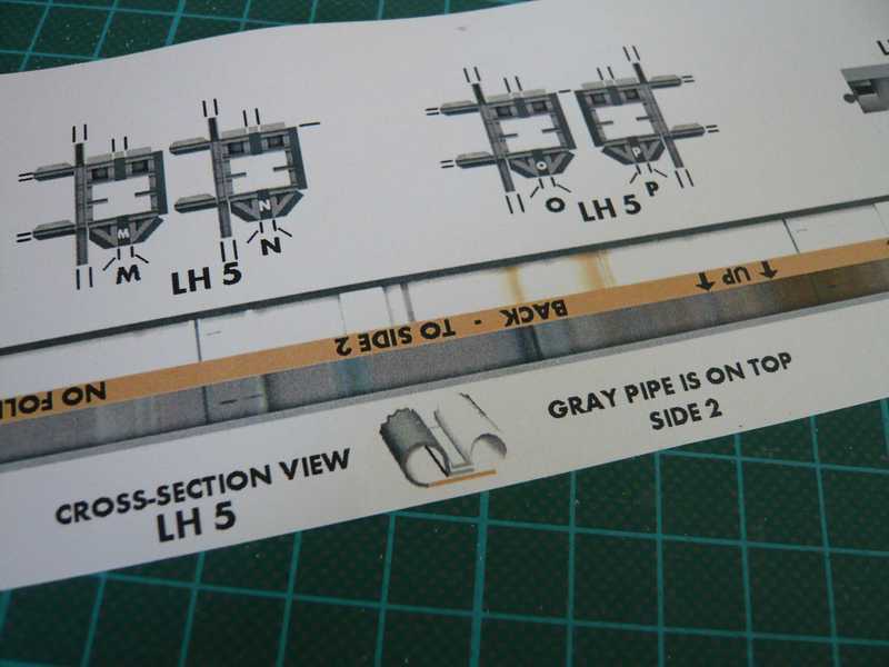 And to all abundance still with these small diameters: From the circumferences of the pipes from the kit one comes for the somewhat thicker LOX-pipe (white) on a diameter of 1.7 mm and for the LH2-pipe(grey) on 1.5 mm. But before I begin with the LOX/LH2-pipes, I wanted to plan after the Right pallet now also still the Left pallet on the Access Platform AP 1, since I know meanwhile, how it looks now with high probability in reality. And also this pallet differs from David Maier's Paper kit. It is a closed frame construction, thus with a cover, but has however no break, something other dimensions, and sits not directly before the MLP wall, but about centrically on the Access platform, as will be to see alike. There is no beautiful complete top view as with the right pallet, but nevertheless good front and side views, on which one can recognize something. In this picture one can see the total length of the pallet, which reaches from Bay 1 to Bay 4, 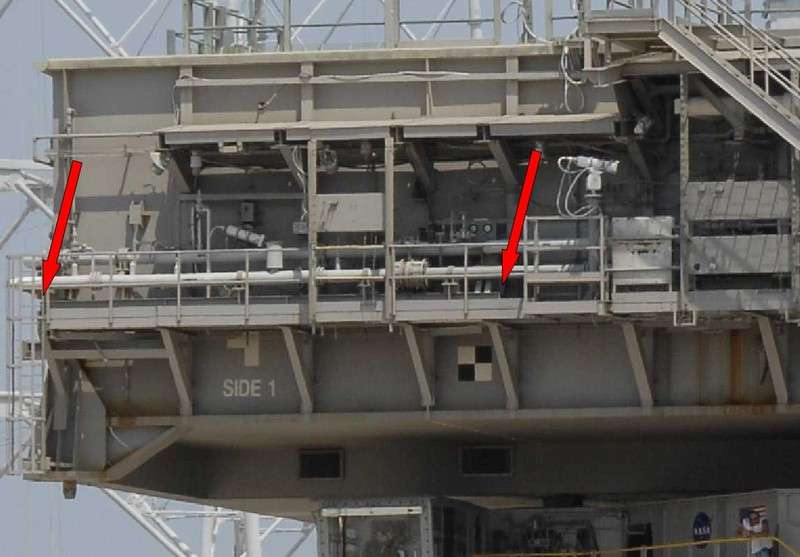 Source: NASA and in this picture the end of left side, from which one can determine the width of the pallet. 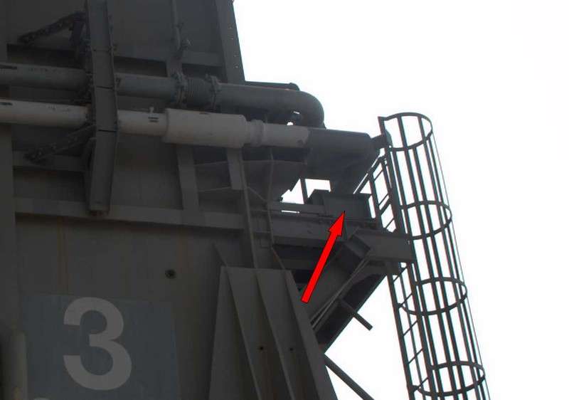 Source: NASASpaceFlight.com (Jay Patterson) And those here are now the individual parts of the pallet, without break, the framework from I-beam (2,4x1,2 mm) and the cover from Sheet (0.4 mm), and behind it to the comparison again the pallet from the Paper kit, with break. 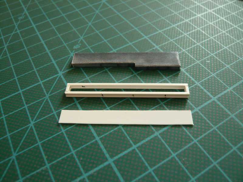 On the pallet there are otherwise only the mounting plates for the LOX- and LH2-pipes, which run in different height and distance from the MLP wall. 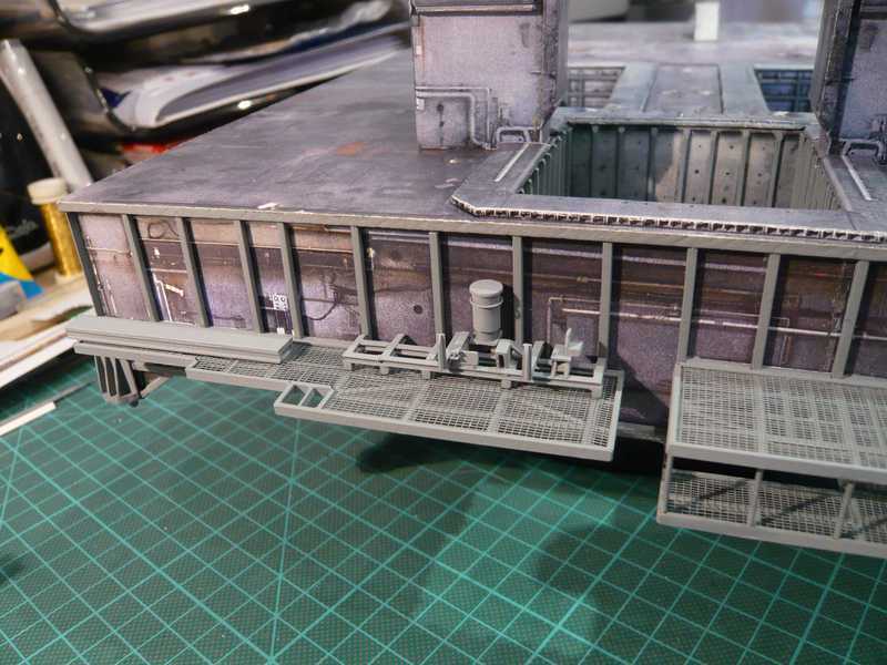 And looks already completely acceptably, as I find. 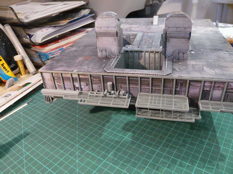 n the meantime I tried to measure the diameters of the LOX/LH2-pipes from reference photos so that the pipes can be installed now finally. I wanted to begin on the Side 2, on which the two LOX pipes run. The something thinner of the two pipes is the white LOX Transfer line, and the thicker (grey) the associated Vent line. I will make the lines however not of paper but from plastic, what appears me simpler and above all more stable. For these two fuel pipes there are eight Pipe supports on the Side 2. And those are in the paper template already considerable mites, which one can recognize in this picture on the basis the size comparison. 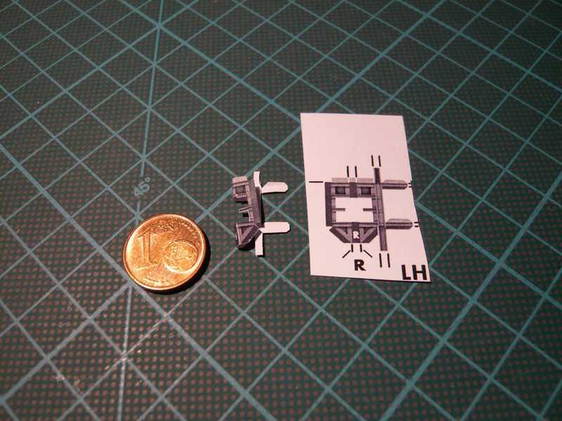 I wanted to try it in any case, however when cutting out and folding already nearly despaired. It concerns gate widths of approx. 1.5 mm, in order those to fold itself several times would have, in order to model from the thing a framework. And that is an almost hopeless venture, because these thin bars very fast can tear up and one can hardly hold anyway. Although I am very patient actually and not like fast give up, I finally let it be and tried something else. With the second support I glued first one half on cardboard (1 mm) and then cut these out, partial without the creases with the shears, the recesses for the pipes however with the cutter, which was to be made just in such a way. Afterwards the second half was cut out and glued on the back. The result one can see here in the next picture. 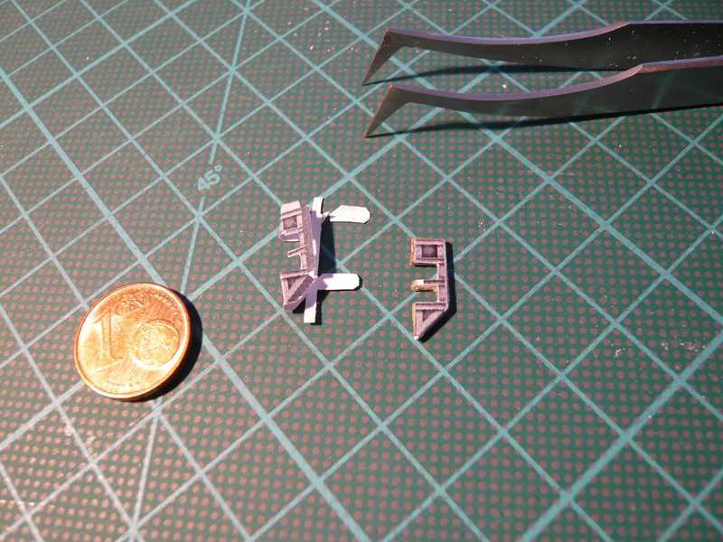 In addition, that is at least practicable, but the support looks not so great, particularly since the Pipe supports in reality look somewhat differently, as one can see in this photo. 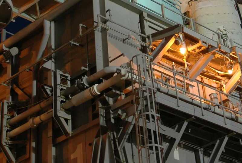 Source: NASA Apart from the only suggested upper free Pipe opening it is veilful me why the Pipe supports are implemented in the Paper kit not as closed frameworks, in addition the middle bar is continuous. Thus all in all that's not a convincing solution, therefore I will try, to scratch-build the Pipe Supports from plastic profiles, although that might become surely also no sugar licking.
__________________
Greetings from Germany Manfred Under construction: Launch Pad 39A with Challenger STS-6 (1:144) Last edited by spacerunner; 10-11-2016 at 07:08 AM.
|
| Google Adsense |
 |
|
|


 Linear Mode

