


|
|
|
#61
 08-16-2013, 04:40 AM
|
||||
|
||||
|
Before it starts with the Pipe supports from plastic, first however again briefly back to the two pallets on the Access Platform AP 1, which I had painted some days before. Afterwards regarded, the cover of the left pallet appeared to me then nevertheless somewhat too evenly/brightly,
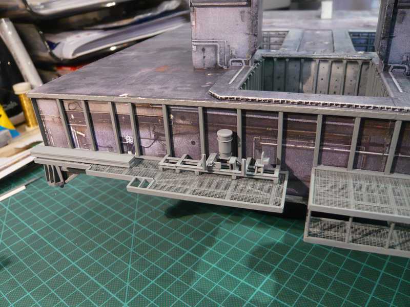 why I adapted it to the color of the MLP deck somewhat. And in such a way it pleases me now nevertheless better.  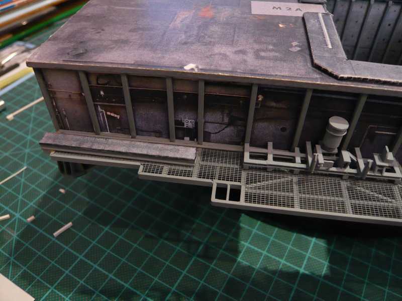 And now to my attempts to scratch-build the Pipe supports on the Side 2 for the two LOX lines from plastic, here again the first prototype from paper/cardboard to the comparison beside the new from plastic. 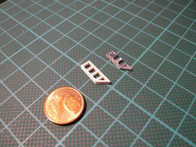 For the front frame parts I used U-Beams 1.7x1.0 mm, and for the remaining parts rectangle profile 1,5x1,0 mm. And it doesn't look bad nevertheless, up to the connection of the lower bevel, and this prototype is already in any case more stable than the paper variant. Completely contently I am not however thereby also because of the different profile thicknesses (1.7 mm - 1.5 mm) yet, why I made still another further attempt. 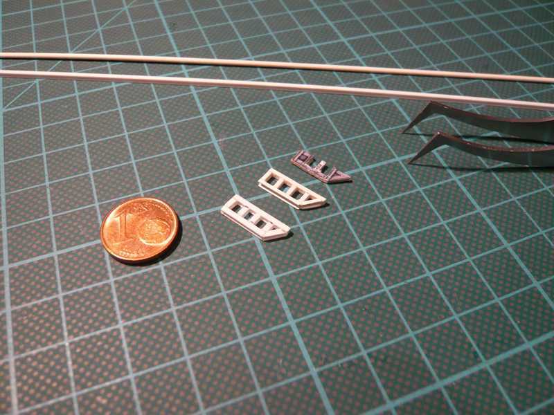 With this prototype (in front) the entire support is from I-Beam 1.5x1.2 mm, which the actual profile thicknesses and profile form better corresponds. Therefore I will remain now with this type and will manufacture the remaining seven supports in the same way. If I had it nevertheless only already ... I've just found a new photo of the Pipe supports at the Side 2, on which one can recognize their structure somewhat more exactly.   Source: NASA How one can recognize on it when high resolution (2 x click), the cross-beams of the supports are not full profiles, as I thought so far, but flat angle profiles on both sides of the framework. And there I thought in such a way, All good things are three, and built still another third prototype of the Pipe support, which copies this structure in approximately, as is to be seen in these pictures: 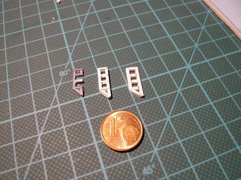 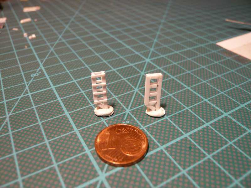 That is the same framework from I-beams 1.5x1.2 mm as with the 2nd prototype, and the cross-beams are Evergreen flat profiles 0.75x0.25 mm, since there are no so small angle profiles. And this support is more delicate and for my taste still a little bit closer to the original than the other one.  And although there are four parts more, this support lets itself manufacture nearly some more lighter than the type of predecessor. And therefore I started with the series production of the remaining seven Pipe supports for the Side 2. But I cut myself first times the individual parts, the frame parts from I-beam 1.5x1.3 mm and the cross-beams from Evergreen StripStyrene 0.75x0.25 mm. That were altogether 77 individual parts, which could be only manipulated with the tweezers. In addition then still Superglue (Pattex Ultra Gel) and toothpicks came for the stressful sticking orgy.  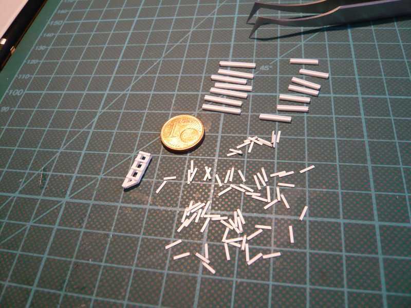 And in such a way the result looks, hardly to believe guys, but it is actually done, and I'm down, but happy.  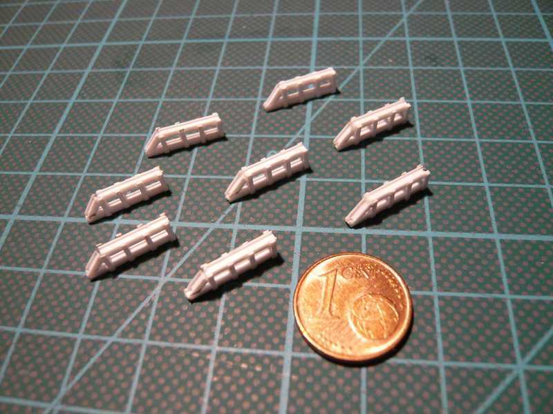 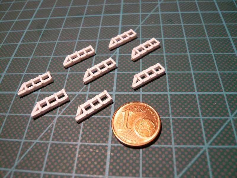 The ends of the cross-beams are now still carefully deburred and/or filed, and then the supports can be tried on already at the Side 2, in order to adapt still the lateral struts. So far for today, thank God,  that would be done for the beginning. that would be done for the beginning. 
__________________
Greetings from Germany Manfred Under construction: Launch Pad 39A with Challenger STS-6 (1:144) Last edited by spacerunner; 10-11-2016 at 10:18 AM. 
|
|
#62
08-16-2013, 02:48 PM
|
||||
|
||||
|
And after the joy promptly the disillusionment came, because there an unexpected problem emerged suddenly. In the transition from the Side 1 to the Side 2 there is a small, but nevertheless serious error in the sheets of D. Maiers kit, which stops for a start the transfer of the LOX Pipes and prepared me headaches.
 As is to be seen in this picture in the original, the lower edges of the bar, on which the first Pipe support sits on the Side 2 (left arrow), and the lower edge of the Access Platform AP 1 on the Side 1 (right arrow) lie on the same line, i.e. thus on same height. 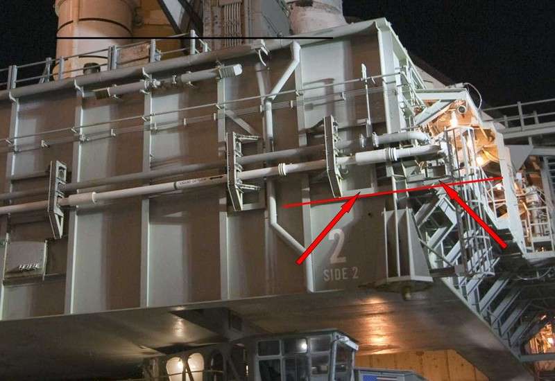 Source: NASA That is unfortunately not in the Kit sheets however like that, as is shown by the following picture. Afterwards the suggested Access Platform AP 1 is on the Side 1 approx. 2 mm more highly than the lower edge of the bar, on which the first Pipe support (s) sits, and thus too highly for the transition of the lower LOX Pipe, particularly since on the Access Platform still the left pallet with a height of approx. 2.5 mm and on it then still the mounting plates of the LOX Pipe sits. 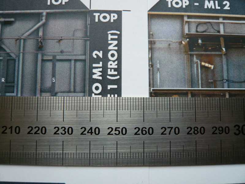 The discrepancy becomes still clearer from the following picture, with which I put a Pipe support with the lower LOX pipe in addition. 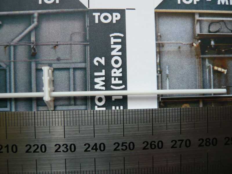 Now please do not disturb you to it that the kit template is on a scale 1:144, my Pipe support however 1:160. One nevertheless clearly sees however, where the pipe walks on the Side 1, and as minimal the gap is between the suggested Access Platform and the pipe lying over it. There now no pallet fits between them, neither with nor without mounting plates with the best will. The matter of price is now, where the error lies? Does the Access Platform sits correctly on the Side 1 or the prop and thus the first Pipe support on the Side 2, which then yes still further seven supports follow? One of both must be changed in the height, or be adapted perhaps also together however, so that the pipings in the height fit. Still good advice is expensive. Therefore I must try now to measure the situation of both components as exactly as possible on the basis of good detail photos in order to be able to decide thereafter on the change. Possibly it come down yes also to a compromise.  The state of affairs is joyless, but not hopeless. Larger problems it would give in any case, if I had to set the Access Platform more deeply, because it glued rather firmly. The state of affairs is joyless, but not hopeless. Larger problems it would give in any case, if I had to set the Access Platform more deeply, because it glued rather firmly.  I property therefore tried out, as it looks, if I shift the pipes so far upward in the pipe supports that still place for the left pallet with its pipe supports on the Access Platform on the Side 1 remains, if I would leave the Access Platform in the height in such a way: 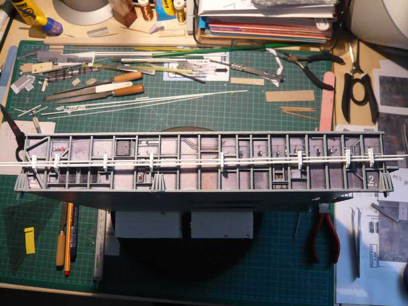 Now would be still enough place for the left pallet, however at least half of the cross-beams for the pipe supports would sit too deeply on Side 2. But somehow this solution does not please me, since the pipes run upward forward too far, so particularly it looks somehow unrealistically, or what do you think? Well times sees, how I will solve that, however actually only the larger evil would remain, in addition I would have to really eliminate the Access Platform AP 1 now again and put it somewhat more deeply, in order to win place, what a horror thought!!! But long speech, short sense, we say in Germany, I bit into the sour apple and decided me nevertheless for the Emergency Operation. The EO was laborious and stressfully, but in the long run successfully, patient is appropriate still in coma, is however surprisingly so far okay. That is the advantage of glueing with Superglue on paper, it holds on very fast, gives way however during bending load then sometime suddenly, and that's mine turn out well. 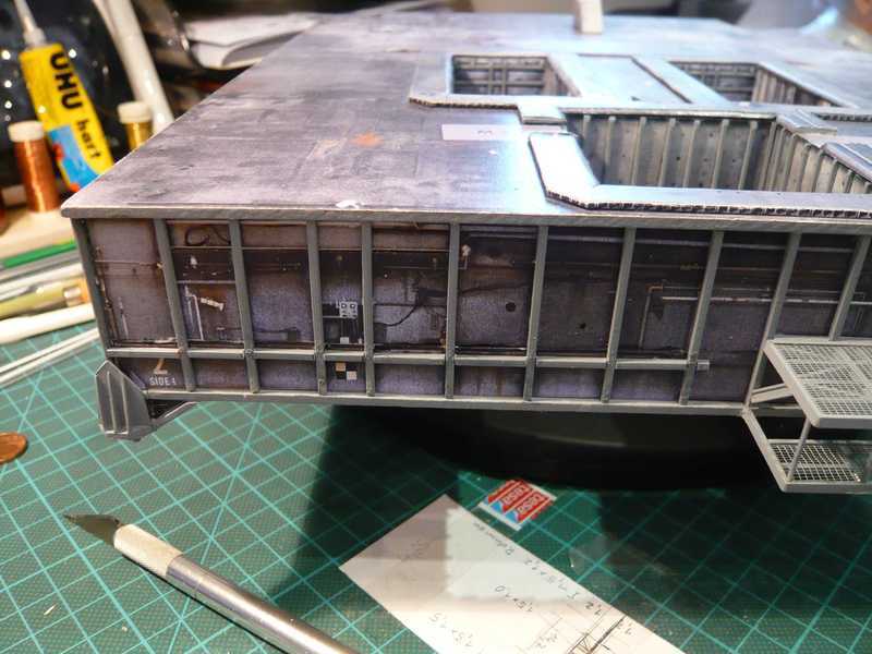 I had introduced the operation myself actually more badly, and/or first than venture nearly offering no prospects. With large caution and patience nevertheless to some extent succeeded then, although I occurred myself thereby however like a dentist, who had to pull all four wisdom teeth at once. Meanwhile the sticking props for the Access Platform are put according to deeper, so that the vertical height is balanced now and the LOX pipes on the Side 2 can run as before. Tomorrow the platform is then again glued to, and then the Pipe supports can be installed onto the Side 2. I consider only just whether I adapt, glue the lateral bracers at the supports still before painting and paint the supports then completely, or whether I paint the supports only still without bracers, afterwards glues to, and afterwards glues the before painted bracers to? That is unfortunately somewhat pedantically with this mixture technology of paper and plastic, but, which is it, thus must I live, nothing is impossible ... After the EO-Repair the platform on Side 1 could be installed and lies now somewhat more deeply. 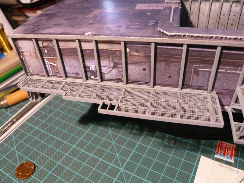 And so place for the left pallet is now also still sufficient, over which the LOX Pipes can run. 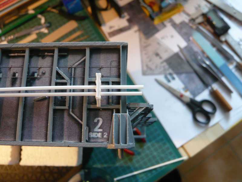 Some little things, except which lateral bracers, have however to be still re-tooled at the Pipe supports. So that the pipings rest upon about centrically in the openings of the supports, still small bearings from Evergreen Strips 1,5x0,38 mm must be applied on the two lower cross-beams. Otherwise the pipes lie somewhat too deeply, which does not look so great. 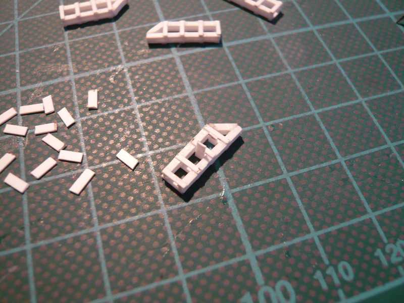 I cut the strips somewhat longer (4 mm), so that it can be glued more simply into the support openings, the overlaying rest after tying the Superglue one cuts off and the edges afterwards carefully one smoothes. Then it is enough in addition with the stressful handling these mites, up to the diagonal bracers, which must be still laterally glued to after the assembly of the painted supports. 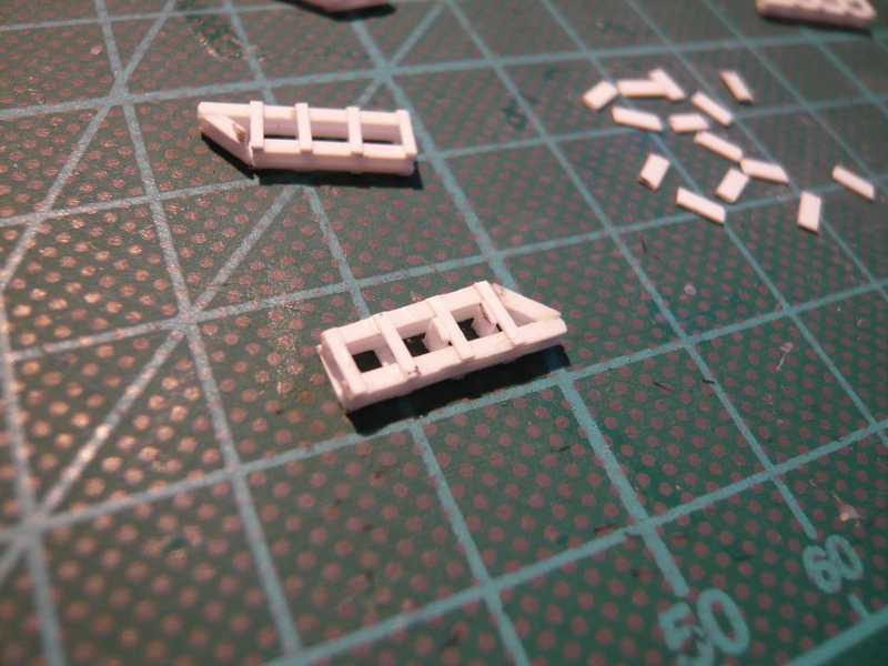 After now all Pipe supports got their bearings, the paint shop could be pleased once again about a larger order in grey. Beside the supports should be painted there also directly still an evergreen profile (0.75x0.25 mm) for the lateral bracers, a round profile (Ø 1.6 mm) for the grey LOX Vent Line on Side 2, a H-beam (2.0x2.0 mm) and an I-beam (2.5x2.3 mm) for bracers and Pipe supports on the pallets on the Access Platform AP 1, as well as the ladders for the two TSM's. 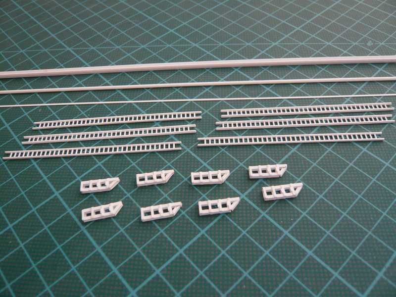 For painting the nice Pipe supports (14.9x4.8 mm) I had to consider myself a retaining possibility. In addition I bent paper clips upward and attached the supports to it with few tiny Superglue droplets. The ladders were fastened with narrow adhesive tape strips to toothpick. 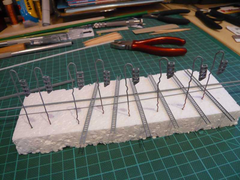 The Pipe supports let themselves solve after painting completely easily from the holding.  Thus nothing more stands in the way now to the assembly of the Pipe supports and the lateral bracers on the Side 2.
__________________
Greetings from Germany Manfred Under construction: Launch Pad 39A with Challenger STS-6 (1:144) Last edited by spacerunner; 10-11-2016 at 10:21 AM.
|
|
#63
08-17-2013, 01:23 AM
|
||||
|
||||
|
Before I begin with the assembly of the Pipe supports, I tried to build the LOX Pipes from the Paper kit. I hope you still remind you of these photos.
  The production of this thin, but with approx. 30 cm relatively long pipes from paper is a delicate process. And so I tried it nevertheless but only with the white LOX transfer line, as one can see here in this picture, over it lie to the comparison a plastic round profile.  Okay, that is feasible in principle, however nevertheless altogether a quite lengthy procedure, until one before-rounded and to a tube formed the paper strip halfway over a core, particularly over this length. And of small breaks that is not at all alike evenly approximately and freely anyway not, and particularly stably already. And now one would have to roll the tube up for glueing first again over the whole length something, in order to put the glue on an approx. 1 mm broad and to approx. 30 cm long fold and then with the glue again cleanly roll up ... I believe, also that is not cleanly feasible without core, and by the way - also not without a nervous breakdown ...  Then one can better take a stable round plastic profile rather, which I will make in any case. And one can bend that then also still around the corner, if it must be. Therefore I have also built the Pipe supports from sheet. Then one can better take a stable round plastic profile rather, which I will make in any case. And one can bend that then also still around the corner, if it must be. Therefore I have also built the Pipe supports from sheet.And now it is finally so far, and the installation of the LOX Pipes on the Side 2 can start up. In addition I aligned first the two pipes for a test between the first and last Pipe support and marked the positions of the supports, which have an easy downward gradient from the Side 1 to the Side 3. I stated to my surprise that there are not only eight, but even nine supports on this side, why still another support had to be ordered additionally. Then I glued together the first four Pipe supports, first the front and rear, and afterwards the second support from the front and one for instance on the side center, and the downward gradient of the lines comes so far completely well. 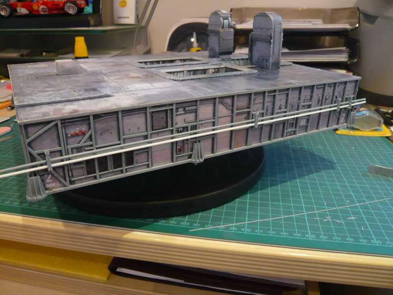 Next the cut of the diagonal lateral bracers (0.75x0.25 mm) for the Pipe supports came to the row. 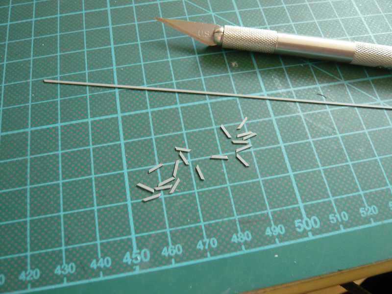 Afterwards I began with glueing of the lateral bracers, which are arranged by the support times on the right side and times left. 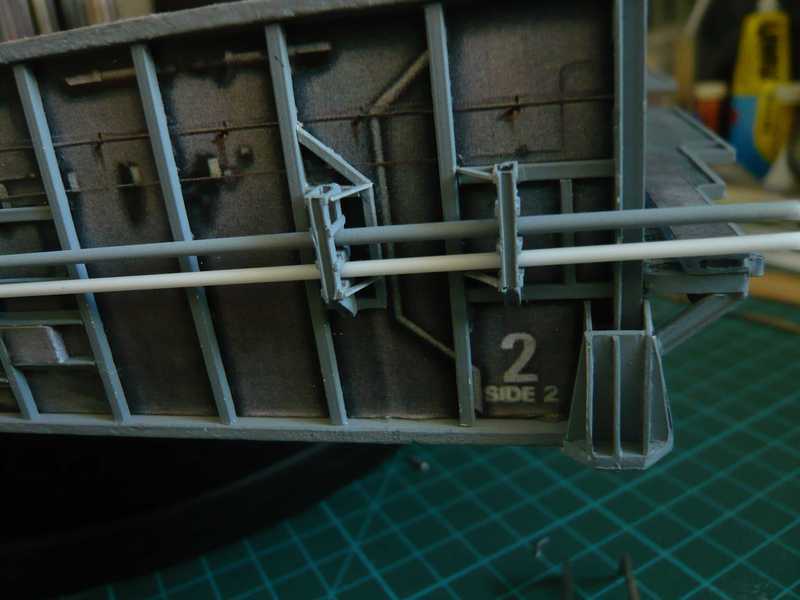 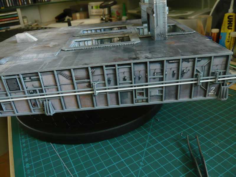 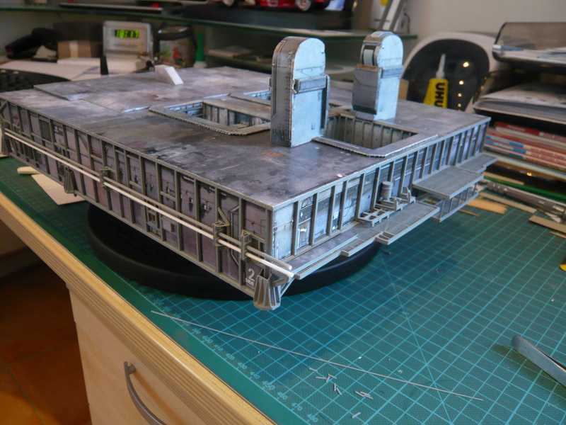 Before there was however still another small aha-experience. When exact looking it noticed to me that there are not only eight Pipe supports on the Side 2, but even nine of them. Thus made something happy to early, and therefore still one support had to be ordered additionally, before the manufacturing sketches disappear perhaps still in sinking. And therefore here only still smaller side trip to a few interesting Pipe details. It would be also too easy to push simply only the two naked LOX Pipes by the supports onto the Side 2 and that was it then, but hello! There are still the so-called Expansion Joints in both lines, or also stretch flanges, as well as shorter, thicker Pipe segments, which occur in each case in different dimensions, therefore here are a few photos in addition: Here first on Side 4 into the LH2-Pipes, where the Expansion Joints are somewhat longer, 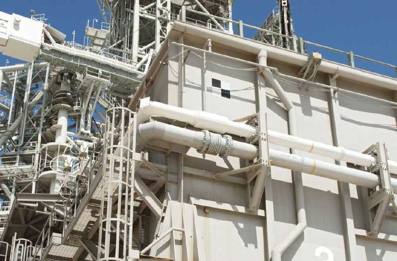 Source: NASA and here on the Side 2 the somewhat shorter building in the LOX Pipes: 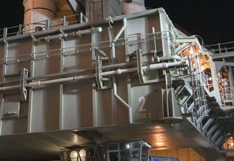 Source: NASA And here one can sees a detail pic of such an Expansion Joint. 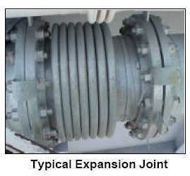 Source: United Space Alliance: STS-111 Flight Readiness Review (2002), GO-18 But naturally the exciting question comes now, how one could probably scratch-build these flanges best? There are e.g. drinking straws, which everyone knows, with which the bends have such bellows, but I only know such straws with approx. 5 mm in diameter which unfortunately is too thick. Therefore I tried out for it first times the following winding technology with simple garden wire. That is the 1.6 mm round profile for the LOX lines, and whereupon on the right a coil from 0.4 mm wire and on the left of beside it with 0.6 mm wire, and on the left of one of line swellings. One must vary there surely still with the wire sizes, whereby the right wire surely seems still to be too thin.  That was now only a all first hand attempt without large precision, and as one sees, the meanderings run inevitably somewhat diagonally. If one is not yet content thereby, one can improve also some more. For such things a view is always worthwhile itself into the decoration department of a tinkering shop, where I e.g. discovered then these small rings, and thought that it could go thereby possibly still better. 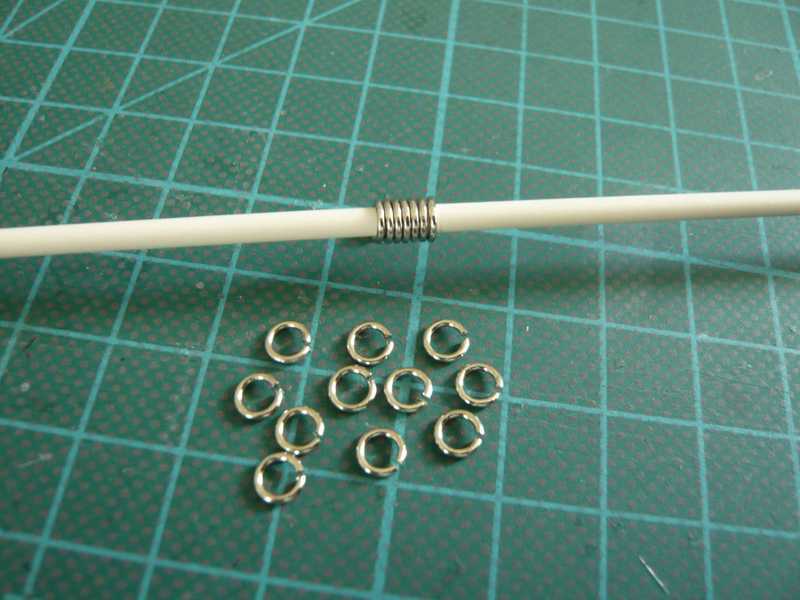 The rings are 0.8 mm strongly, have an outside diameter of approx. 4.5 mm and would here be a possible option for the thicker LH2-Vent Pipes on the Side 4 with 2.7 mm outside diameter. In addition an attempt with these rings, which I planished and easily bent together somewhat. Several such rings drawn up next to each other on the round profile, such a stretch flange were then showed, still without gluing. 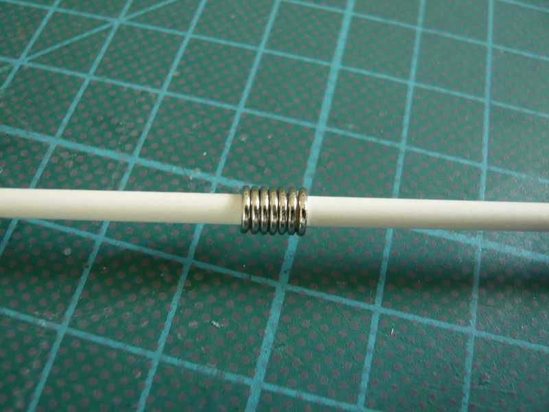 And I find, whereupon can be constructed, or? And which do you mine in addition? Or are there possibly still better proposals?
__________________
Greetings from Germany Manfred Under construction: Launch Pad 39A with Challenger STS-6 (1:144) Last edited by spacerunner; 10-11-2016 at 10:24 AM.
|
|
#64
08-17-2013, 10:39 AM
|
||||
|
||||
|
Manfred, I am really enjoying following your project. great work, and great detail!
Chris
|
|
#65
08-17-2013, 02:28 PM
|
||||
|
||||
|
Thanks Chris for your compliments!
I will show you more.As I see, there are no better proposals for scratch-building of the Expansion Joints. : With the exact comparison with the detail pic of the Expansion Joint (EJ) it noticed to me that the proportions of my solution with the rings, presented last, seem to be correct nevertheless not completely. In addition the rings with a thickness of 0.8 mm are nevertheless somewhat too strong in relation to the pipe diameter of 2.8 mm for the LH2-Vent Line on the Side 4 and should be rather somewhat thinner. Therefore I checked for the examination of the proportions the dimensions of the EJ on the detail pic again, and came thereby on the following proportions: EJ-Diameter:Pipe-Diameter=1,4 as well as EJ-Diameter:EJ-Ring-Thickness=9,5. And from this follows e.g. for 2.8 mm pipe diameter a thickness of the EJ-Rings of 0.4 mm, which might show a more realistic picture than with 0.8 mm rings. For the LOX-Vent Line on the Side 2 with 1.6 mm in diameter would result thereafter a thickness of the rings of 0.25 mm. And thus my all first coil with the thinner wire did not lie at all 0.4 mm so far away, which however first not at all like it looked. On Macro photographs such details look always rather clear, although these differences from normal point of view will not be noticeable probably however at all so much. Thus I will have to look around for appropriate wire sizes.  Since the procurement some more drags on, I concerned myself in the meantime with a further nice MLP detail somewhat more extensively. Here again a photo of the Ladder Cages, which are installed at both corners of the Side 1.  Source: NASA In David Maiers kits look these baskets in such a way: 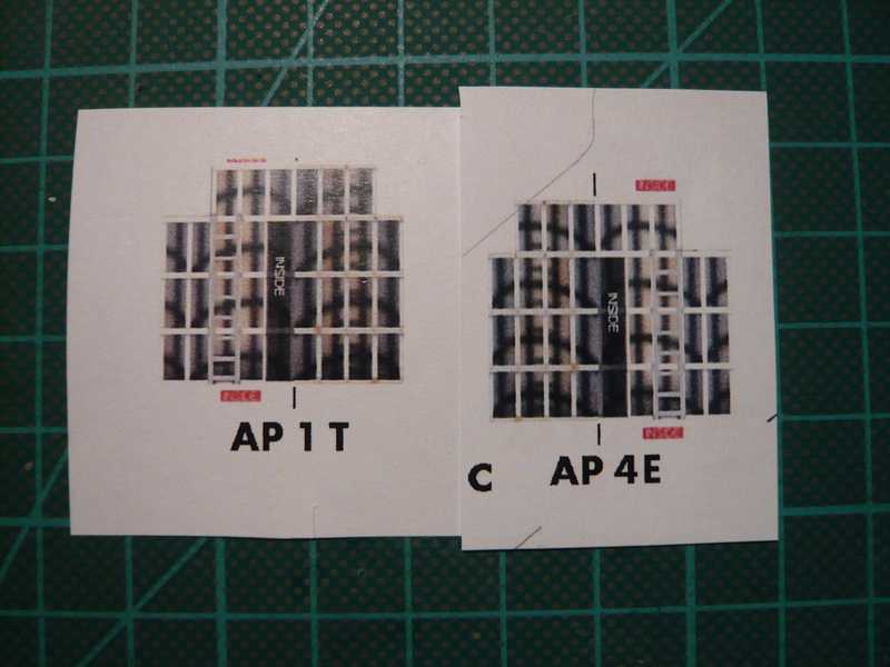 That would be then only such obscure tubes with the suggested outlines of the baskets, which would not please me however at all, that's an absolute NO Go! Therefore I originally wanted to procure myself for it the PE-kits for fire ladders for the trace N, which would fit from the size well, which would cost however again something. Therefore I considered for a long time back and forth to what one could take for it possibly for improvisation, in order to save for something work and costs. Since I found however no suitable lattice or similar aids, I thought that I could scratch-build the baskets possibly also from thin Evergreen profiles, the suitable ladders I had already procured myself for the two TSM's. In order to be able to start correctly, one needs naturally first however only some dimensions. And therefore I have searched my picture collection for good Hi.Res.-Photos and evaluated appropriate photos, measured i.e. diameters, distances, wall thicknesses etc.,converted it on 1:160 and not badly been astonished, which for delicate mites would become. For the baskets one needs rather thin Strips, whereby I decided in the long run for 0,25x0,5 mm. Next I considered myself the fact that one does not manage probably without template and without a core and has looked for appropriate round material with approx. 6 mm in diameter and made me a sketch of the completion of the basket . Then I tried to bend a Styrene Strip around the core to windings and under a hot-air hair dryer to rings in hope that they maintain afterwards their diameter, which also in principle goes, although they expanded themselves again somewhat. 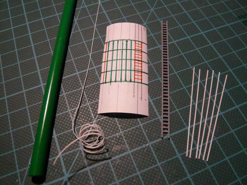 Therefore I started a next winding attempt and used a core with smaller diameter and wound the strip more carefully under hot-air, which supplied better rings. 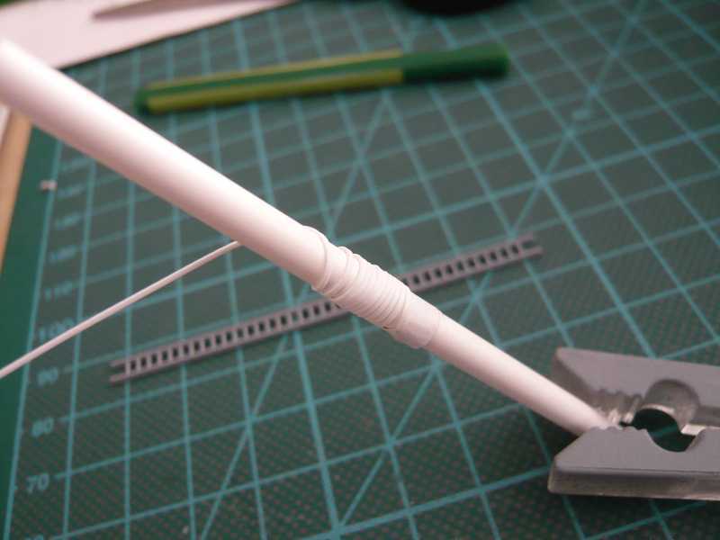 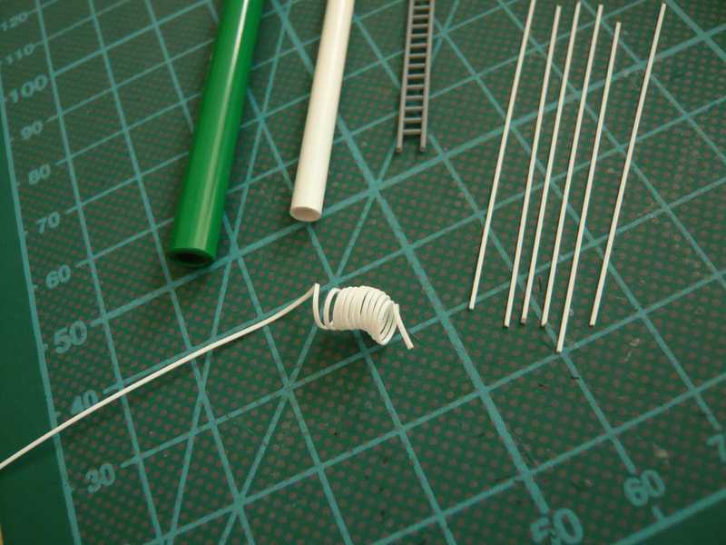 Since the use of the completion sketch as template for sticking the bars and rings together on the core would have led to the enlargement of the basket diameter, I had in the long run done without it. Afterwards I have drawn the location of the strips and rings on the core and whereupon first fastened the ladder and the longitudinal bars with tape. 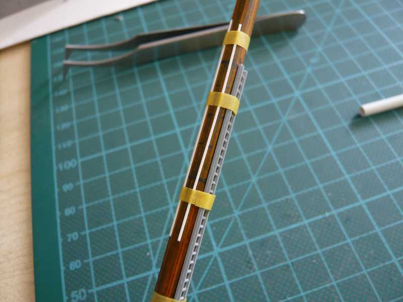 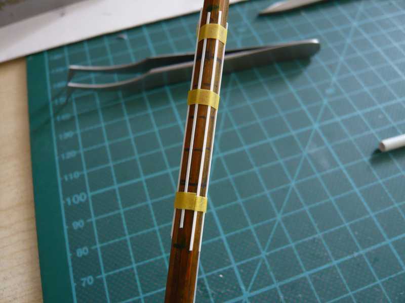 Afterwards the rings were roughly cut, 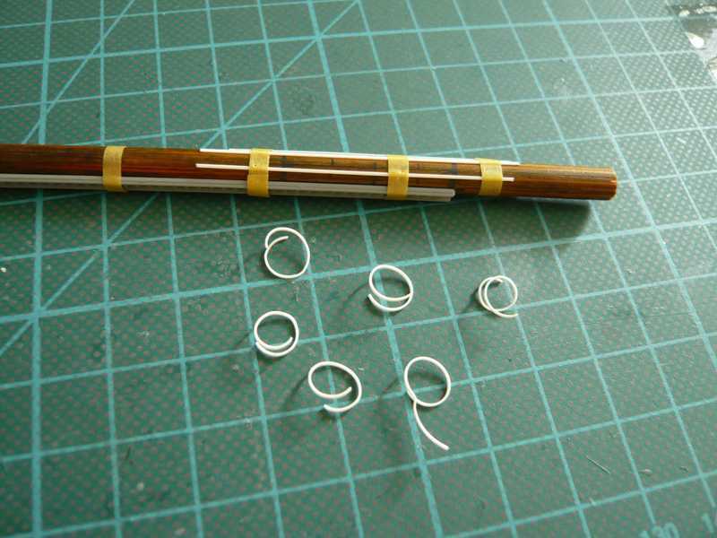 and afterwards glued with Superglue around the bars, which was however not completely so simple.  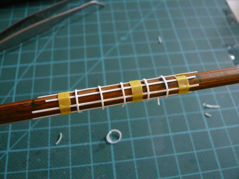 There were easy problems with the replacement of the ladder basket of the core, which stuck nevertheless in some places. With the careful loosening of the splices I had to watch out infernally, since the 0.25 mm thin strip can't bear not very much and could easily break. There I must be still more careful when next sticking and dab less Superglue. 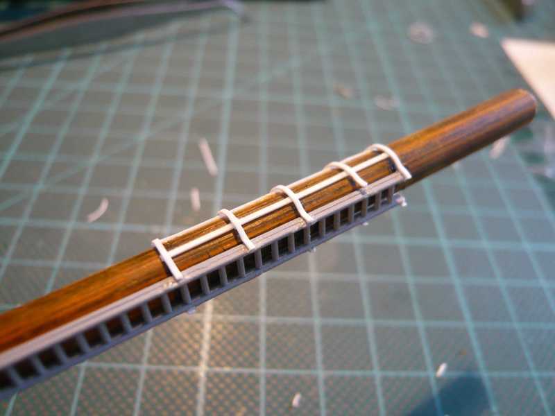 But in the long run nevertheless succeeded in getting the basket down welfare and cutting on length, and it looks nevertheless completely tidy, as I find.  And in such a way then the provisional fitting at the MLP looks. 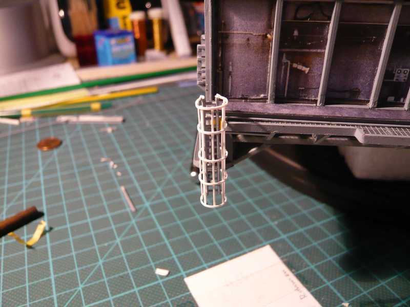 Now the upper exit beside the ladder must be only opened and the basket afterwards be painted. With the result of my prototype I am so far completely content, with somewhat more exercise could next perhaps even some more better succeed.
__________________
Greetings from Germany Manfred Under construction: Launch Pad 39A with Challenger STS-6 (1:144) Last edited by spacerunner; 10-11-2016 at 10:32 PM.
|
| Google Adsense |
|
#67
08-18-2013, 12:37 AM
|
||||
|
||||
|
Thanks Firewing for the kind words!
These details are always new and interesting challenges for scratch building.
__________________
Greetings from Germany Manfred Under construction: Launch Pad 39A with Challenger STS-6 (1:144) Last edited by spacerunner; 10-12-2016 at 03:53 PM.
|
|
#68
08-18-2013, 12:46 AM
|
||||
|
||||
|
So, and because the first prototype already had succeeded completely well, directly still the second ladder cage should follow. Now I have refined some handles somewhat, whereby the procedure should be simplified.
This time I've glued the vertical bracers next to each other in the necessary distance on two thin masking tapes. This 'bracer lattice' I put then around the core and fixed it together with the ladder with some masking tapes too. That could be done in any case more simply than with the first time, I had presented the bracers just separately and had fixed them successively with masking tapes. And then again rings under the hot-air hair dryer were wound and cut from it. 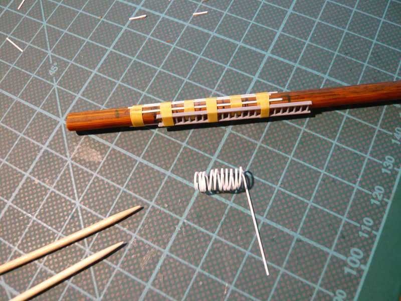 Afterwards I glued the first ring only at one side of the ladder as starting point. After the Superglue has hardened I pulled the ring loop something to the side and successively dabbed all splices on the bracers with Superglue and immediately thereafter pulled the ring loops with the tweezers in one turn around the bracers and let them glue. One can still make quite small position corrections, if one hurries somewhat. And in such a way that could be done actually completely well and the ring sat rather exactly on the marking. 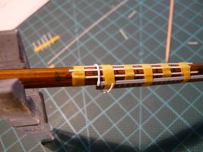 And here the other side with the endpoints. The supernatant ends were cut off and finally all outside splices to the ladder were carefully sanded. 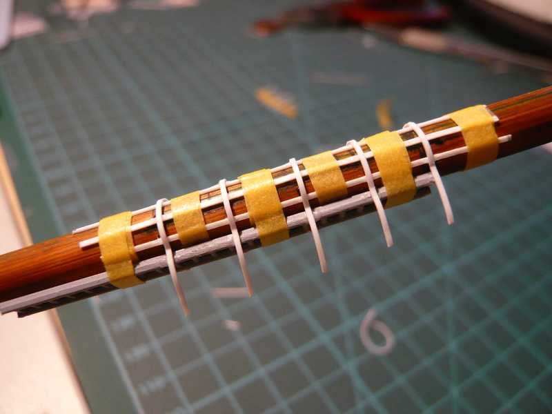 And there now both ladder cages stand and wait for the finish, the recesses for the exit and in the end the painting. 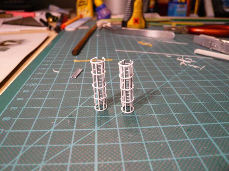 And to the end still a question for the eagle eyes among you: How do both ladder cages differ, what do you think? 
__________________
Greetings from Germany Manfred Under construction: Launch Pad 39A with Challenger STS-6 (1:144) Last edited by spacerunner; 10-12-2016 at 03:55 PM.
|
|
#70
08-18-2013, 03:35 AM
|
||||
|
||||
|
39a with Challenger...
Manfred,
Every time that I come by to read your posts, the newest one out-dos the previous ! Your build truly belongs in the Smithstonian. But....If it were there....you couldn`t admire it! I really enjoy following your thread! Bill
__________________
----------------------------------------------- Seems to have been Deliberately Buried ----------------------------------------------- Where did Gunter Wendt ?
|
| Google Adsense |
 |
|
|


 Linear Mode

