


|
|
|
#81
 08-21-2013, 04:01 PM
|
||||
|
||||
|
Thanks Wad Cutter for all the kind words!
 Your comments give me encouragement to keep pushing on. Your comments give me encouragement to keep pushing on.  I am delighted when you inspire these details. Stay tuned!  
__________________
Greetings from Germany Manfred Under construction: Launch Pad 39A with Challenger STS-6 (1:144) Last edited by spacerunner; 10-12-2016 at 04:26 PM. 
|
|
#82
08-21-2013, 11:54 PM
|
||||
|
||||
|
Hello, and let's go!
Here are the two remaining Pipe supports for the LOX-Vent line on the left pallet. 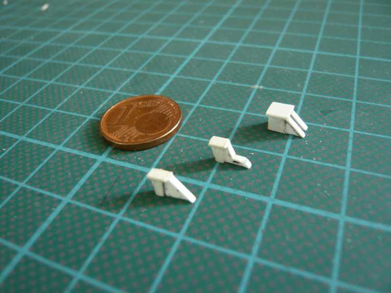 As you can see, the second support differs from the first by a cut-out, and that has its reason. Repeated exact looking at the supports on photos I noticed, that the LOX-Transfer line running immediately in front of the supports of the LOX-Vent line exactly at this point has an Expansion joint (green arrow), which takes his place. :  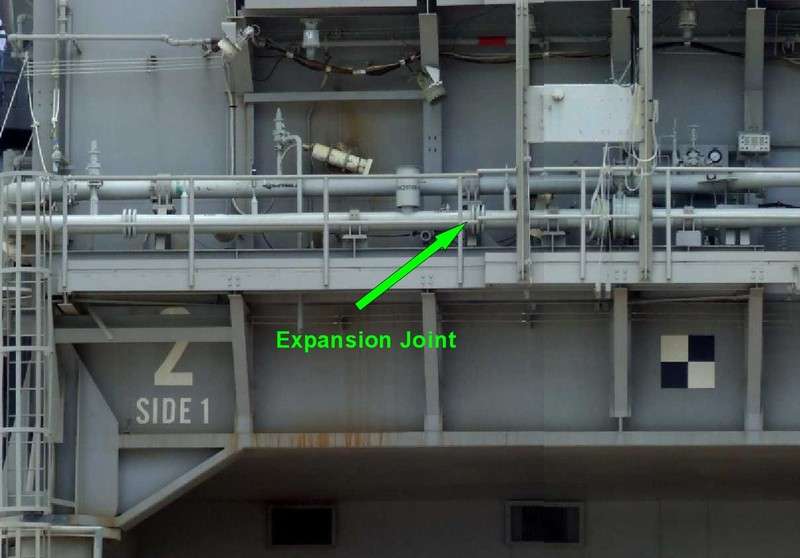 Source: http://www.capecomespace.net And so look the supports on the pallet. 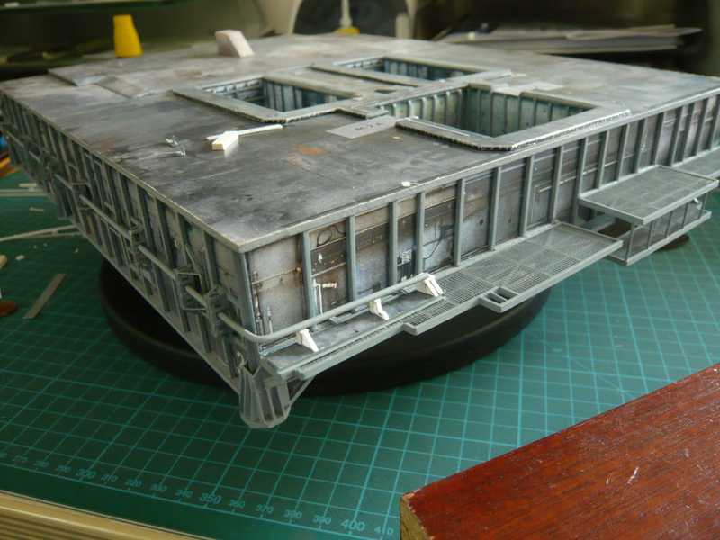 Then I have looked again in the paint shop and asked me after the progress of work,  but so far all has been prepared and wanted to get started right. The ladder cages also still were on the list. 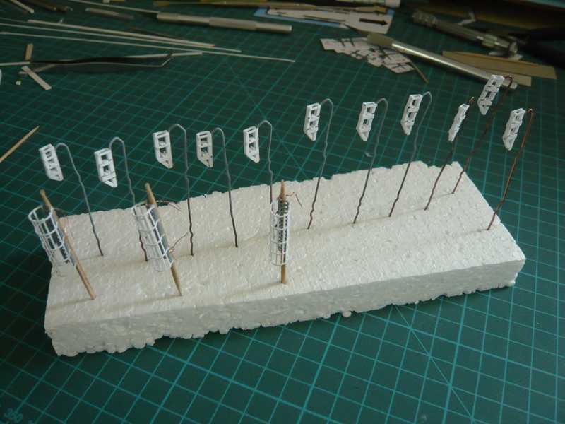 And behold, it goes forward but. The grey LH2 Vent line and the Evergreen's profile for the oblique bracers with same they painted, great job done.  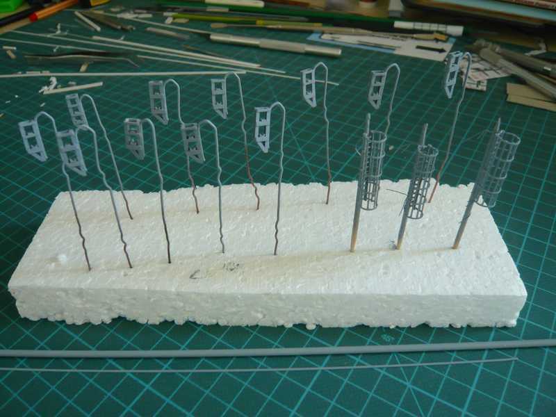 And the Ladder cages are now also as far as ready for the assembly, are set but still aside. A joint had resolved itself and must be glued again. 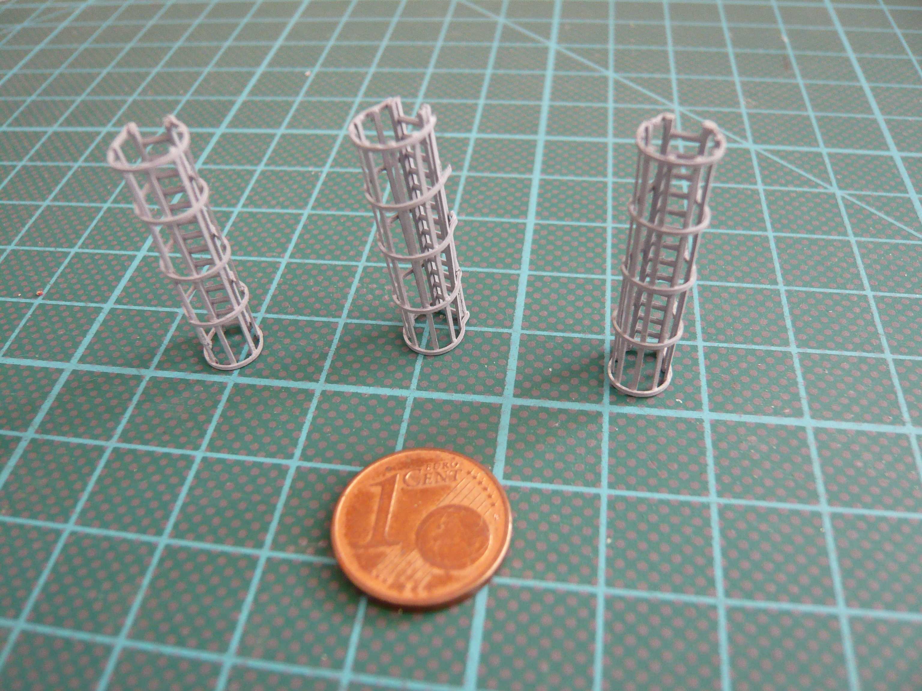 Now can it go actually with the assembly of the Pipe supports on Side 4. Here, only the different sizes of supports must be observed so that then the gradient of the pipes is also true. 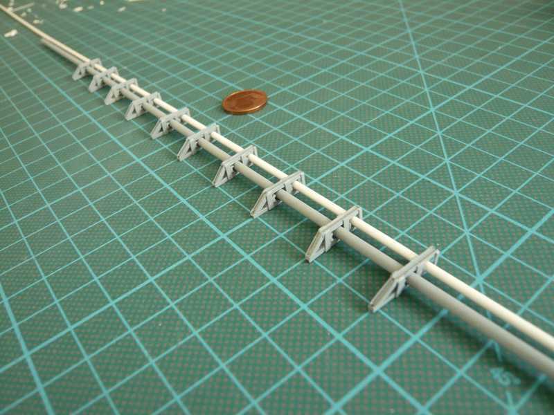 That is now done, and thus the Side 4 looks now also already quite passable. 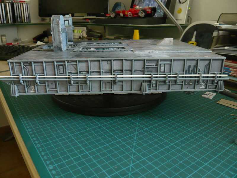 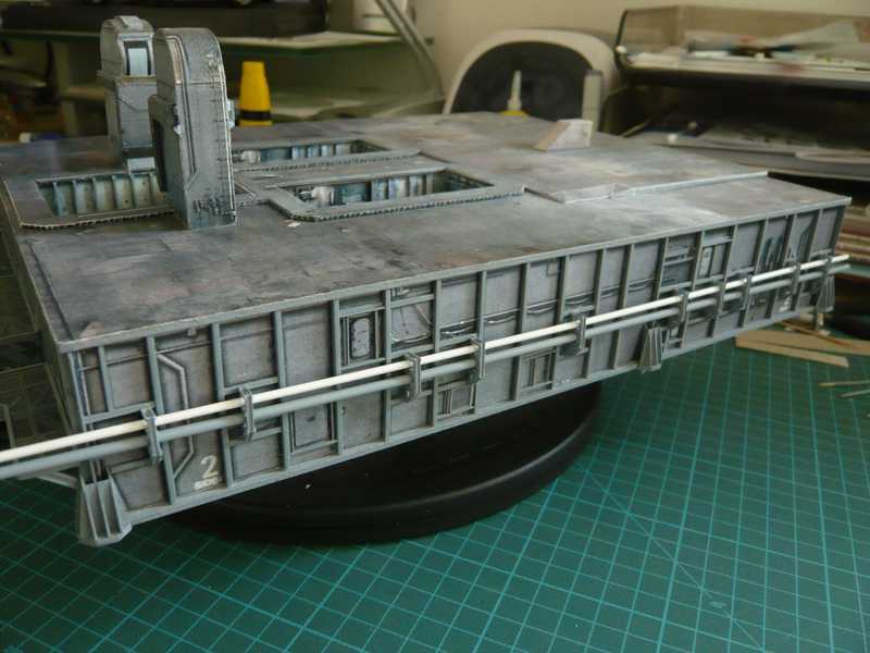 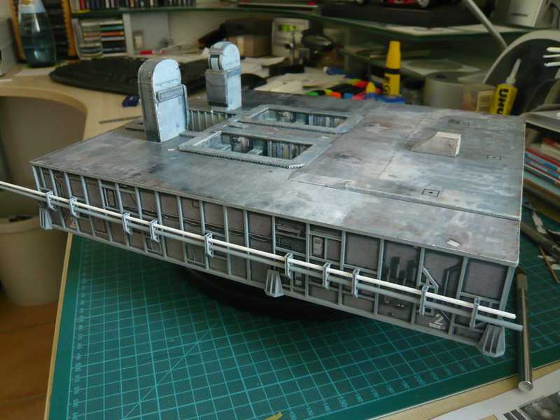 And here again something up close. 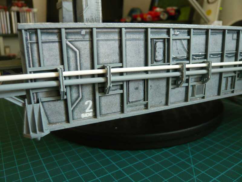 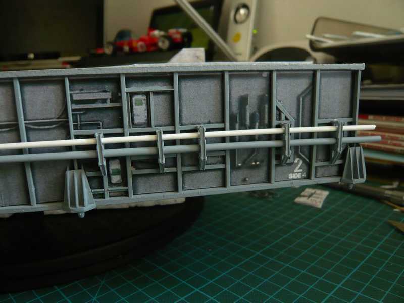 Now, only the lateral oblique bracers missing, which are to be installed next.
__________________
Greetings from Germany Manfred Under construction: Launch Pad 39A with Challenger STS-6 (1:144) Last edited by spacerunner; 10-12-2016 at 04:35 PM.
|
|
#83
08-22-2013, 10:16 AM
|
||||
|
||||
|
And here is a further update, so to speak, the look-up to the Pipe supports on Side 4.
There were to assemble "merely" the lateral bracers, are installed the times right, time left, but from photos like this in HiRes (click) is good to see.  Source: NASA And here are the prepared 20 bracers from Evergreen strip 0,75x0,25 mm for the 10 pipe supports: 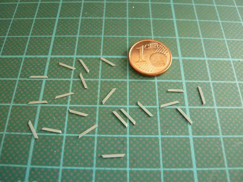 The glueing of the bracers with Superglue was again nothing for the faint-hearted, but rather what for quiet hands, and was hard to make without stopping your breath when attaching the bracers to the supports.  But ultimately all bracers sit in place, thank God. And that seems out of Side 3 to the front to Side 1: But ultimately all bracers sit in place, thank God. And that seems out of Side 3 to the front to Side 1: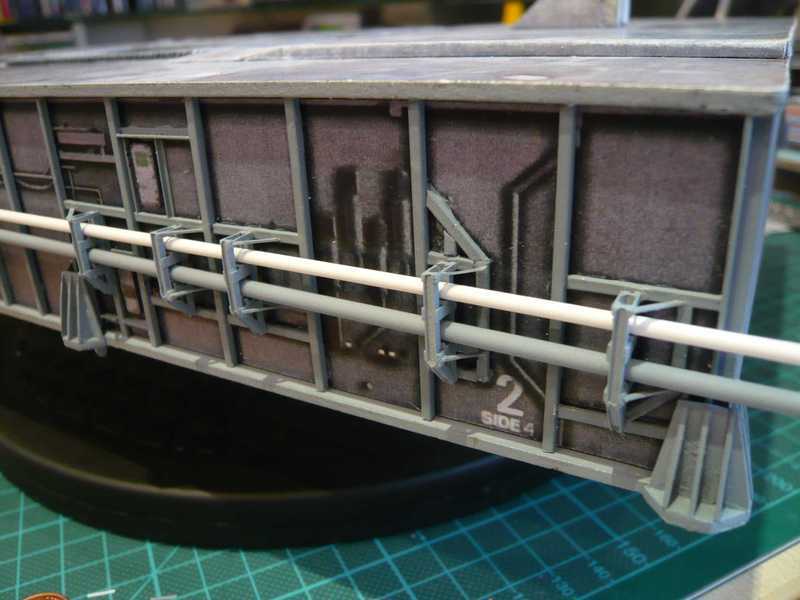 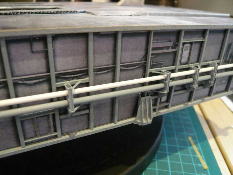 The different side order of the bracers should be to recognize. 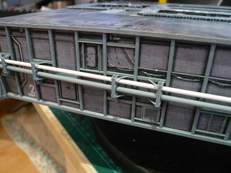 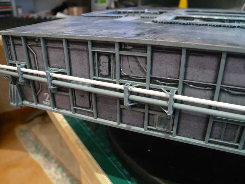 So, that's it then for today, and stay tuned!
__________________
Greetings from Germany Manfred Under construction: Launch Pad 39A with Challenger STS-6 (1:144) Last edited by spacerunner; 10-12-2016 at 04:36 PM.
|
|
#84
08-23-2013, 01:03 AM
|
||||
|
||||
|
And here is a further update on Side 4, because we are just so beautiful here. Before there the LH2 pipes will be permanently installed, there is a nice little detail to build, which would make otherwise unnecessary circumstances. There are namely in the Bay 16 four so-called Pneumatic Vent Mufflers, how I now have be explained. These elongated parts here are:
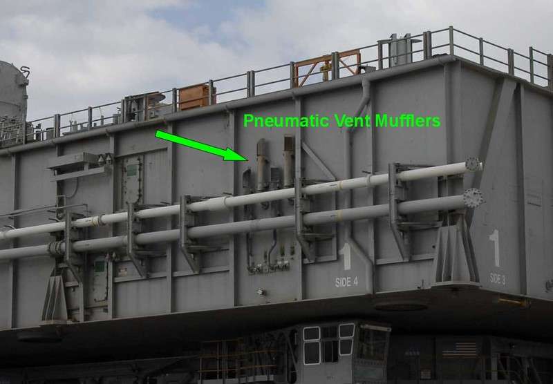 Source: NASA On Side 2 there are two similar vent mufflers in the Bay 3, which are arranged horizontally: 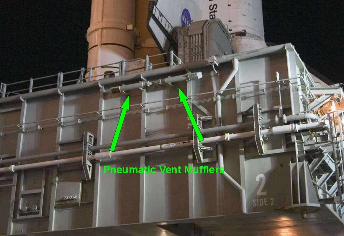 Source: NASA These parts are pneumatic outlets for venting the LH2- and LOX-Vent lines, because without ventilation are not a fuel that could be otherwise filled through the Transfer lines. The Vent mufflers on Side 4 look in the Paper kit: 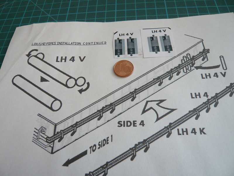 Only simple tubes, with the lower lines are only hinted at what was released but again too simple would be. Here, such model is time to see. 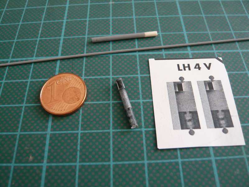 Because I don't love so much these implied Maier Kit Details, I wanted to scratch-build the mufflers first fully plastic and had been prepared already the two round profiles. Then I have only scratch-built the bottom lines and used but the upper parts with the opening, what looks together quite well: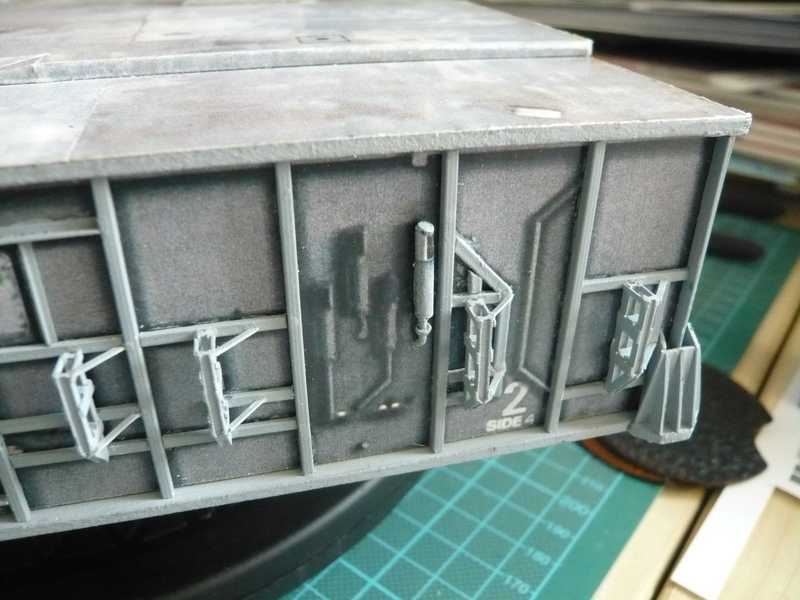 Here I however separately glued the glue seam of the tube, so that is not an edge, and glued a plastic core to stabilise and a small U-beam as bracket. The line is a 1 mm round profile with a ring made of 0.5 mm lead wire to hint the connection clamp. And so the other three Vent mufflers look: 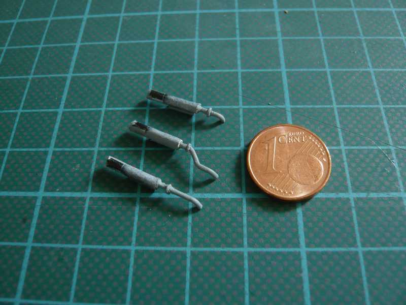 And here after mounting on the MLP wall: 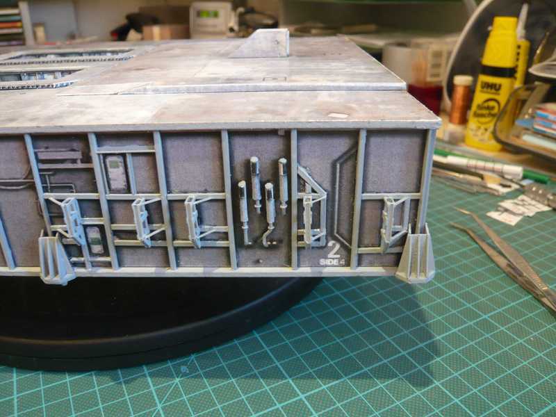 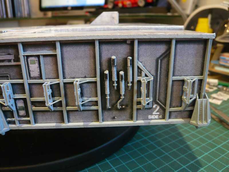 And here you can see now probably also why the Vent mufflers had to come before the final installation of the LH2 pipes tuned. 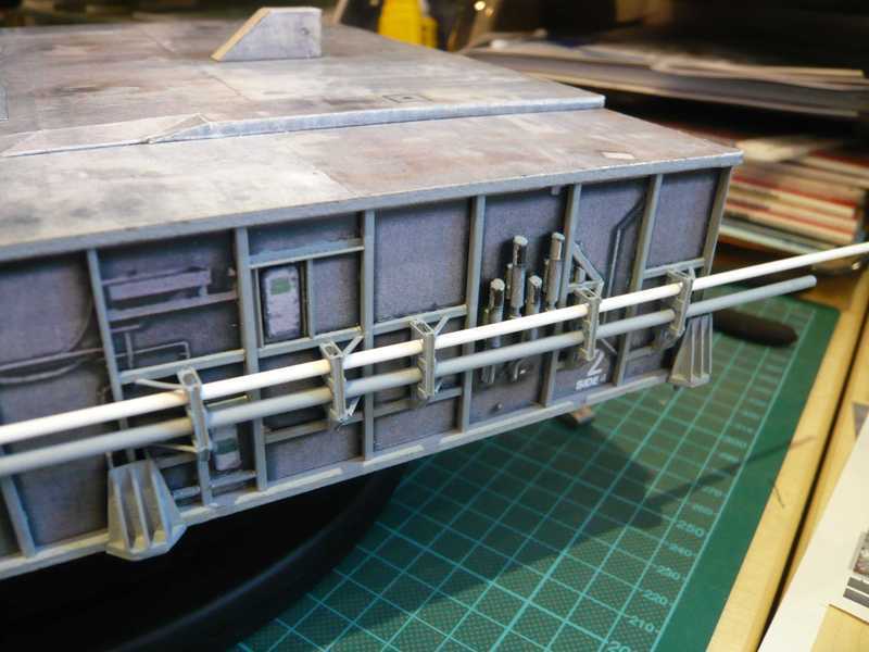 So long.
__________________
Greetings from Germany Manfred Under construction: Launch Pad 39A with Challenger STS-6 (1:144) Last edited by spacerunner; 10-12-2016 at 04:37 PM.
|
|
#85
08-24-2013, 12:01 AM
|
||||
|
||||
|
And because I was just at such small things, here a short update concerning furter pipe brackets details. There are next to the Expansion joints even so-called Pipe anchors. Additional brackets which will probably stabilize these slightly weaker areas of the fuel pipes are as seen here in the picture on the Side 4 in the detail right can see above. The front 3rd Expansion joint on this side (far left) is stabilized by the corner-pipe support at the Side 1.
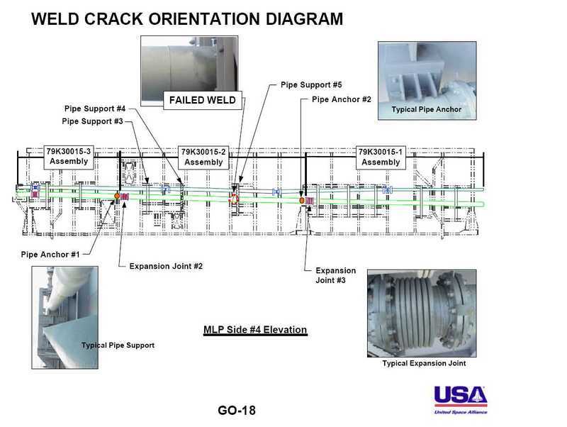 Source: United Space Alliance: STS-111 Flight Readiness Review, GO-18 (2002) These are only very small parts, which can hardly be seen behind the pipes, but they are now included. And since I now know that they exist, I tried also to scratch-build this. Since they directly sit on the vertical reinforcement bars, I have used H-beams 2,5x2,3 mm, at least to indicate the anchors. 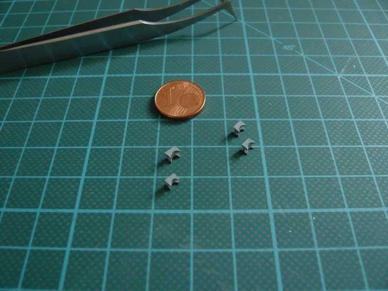 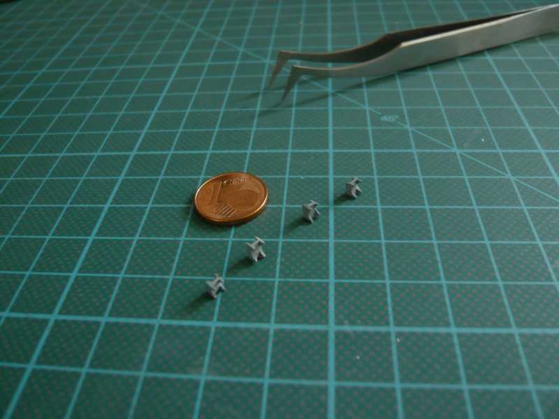 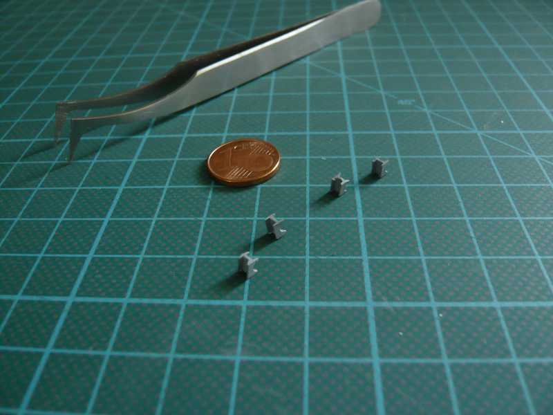 So, I will return to the Side 2 and want to finally start the installation of the LOX-pipes. But first I must scratch build the corner pipe support, here relatively good to see is in these two images, so that one can identify in about the dimensions for scratching. 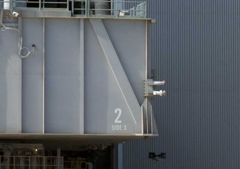 Source: NASA 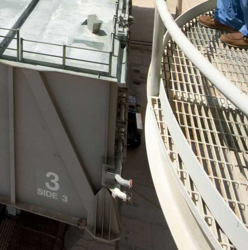 Source: NASA First the small bars from Evergreen strips 1,0x0,2 mm or 2,0x0,2 mm were cut and then glued, which sit on both sides of the corner angle profile under the base plate. 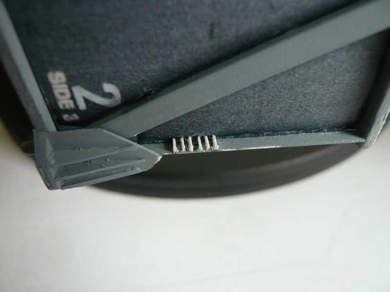 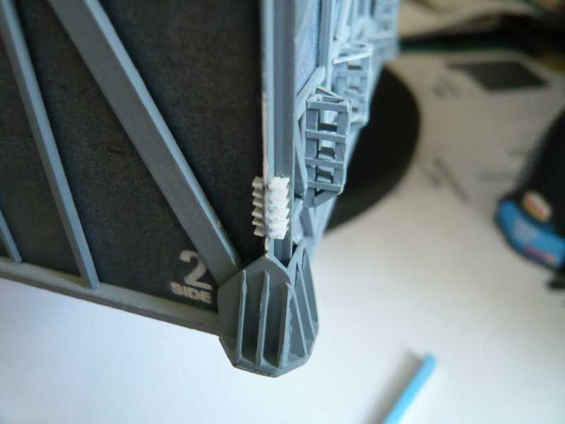 Unfortunately my digicam having a hard time generally somewhat with the resolution of white parts, however I will not deprive but the recordings you. Then was glued the base plate made of 0.3 mm sheet for the two pipe holders now. 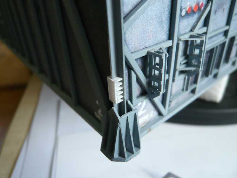 The holder for the upper grey Vent line corresponds to about a H-beam 1,5x1,3 mm, I just but not had in stock. Therefore I made it from Evergreen strip itself and filed the semicircular openings for the pipe. The two pipes are inserted here only provisionally. 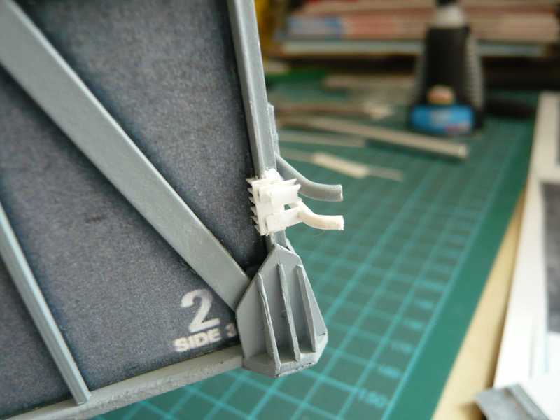 The holder for the lower white Transfer line is here already with glued, it is missing but the triangular lock for the bow, which, in contrast to the vent line is not rounded but segmented. Because the transfer lines are vacuum jacketed double-walled pipes, these cannot be bent easily as the vent lines. I will install but only the transfer line this stiffening triangle after bonding, is here to see the segmented bow. 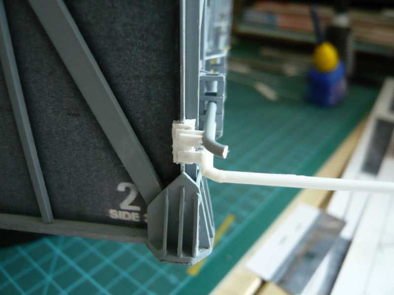 And with grey colour which looks now just something more friendly. 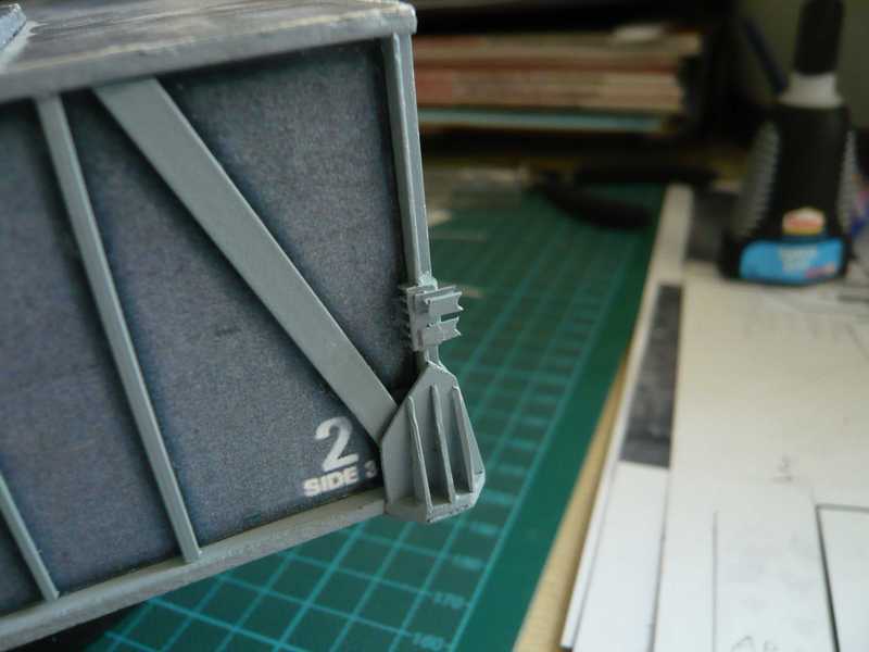 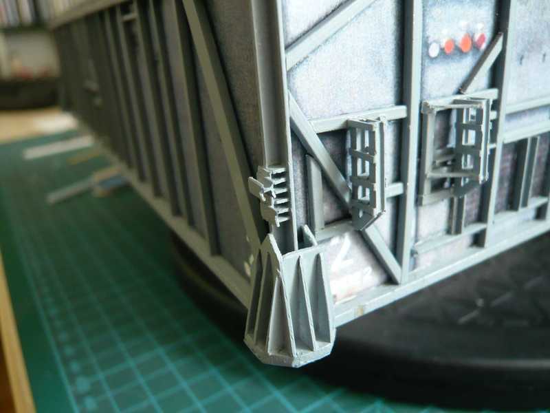 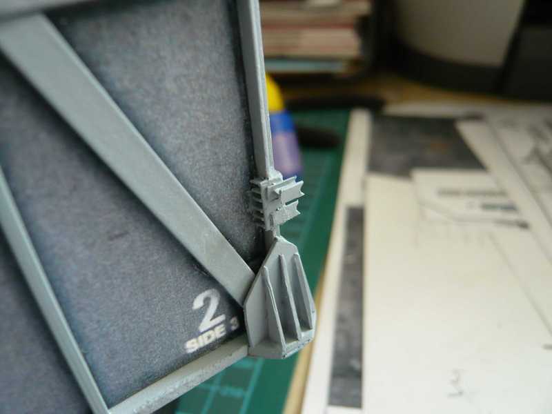 And so the little things that really can stop one are but omit I don't want they therefore also. As far as for today.
__________________
Greetings from Germany Manfred Under construction: Launch Pad 39A with Challenger STS-6 (1:144)
|
| Google Adsense |
|
#86
08-24-2013, 10:49 AM
|
|||
|
|||
|
I'm sitting in front of my screen watching all these tiny bits and pieces come together. This is absolutely remarkable, incredible and unbelieveable. Great work, man! :-)
|
|
#87
08-24-2013, 12:43 PM
|
||||
|
||||
|
Thanks Revell-Fan for your appreciative words.
BTW, the biggest challenge is still before me, when I get to the Access Platforms on Side 1, especially with a lot of pipes, equipment and fittings of the LOX and LH2 Valve skids. This makes having a headache now and will probably become Modeling Madness ...
__________________
Greetings from Germany Manfred Under construction: Launch Pad 39A with Challenger STS-6 (1:144) Last edited by spacerunner; 10-12-2016 at 04:39 PM.
|
|
#89
08-24-2013, 02:05 PM
|
||||
|
||||
|
Thanks eatcrow2 for the nice words, I also love the details.
Therefore it continues with some details of the LOX-Vent line on Side 2. There are a total of three Expansion joints, the structure of which was already seen in earlier photos. I started with the expansion joint in the Bay 18 at the end of Side 2, which sits between the corner angle profile and the first Pipe support. Then there is still the second a little further right in Bay 13, and the third is in Bay 1 at the front of the Side 2. First I have wrapped rings for the mutual flange joints of square profile 0.5x0.5 mm and then bent under hot air and separated some. 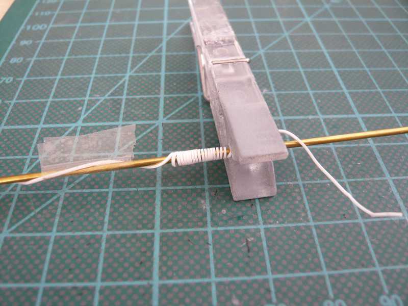 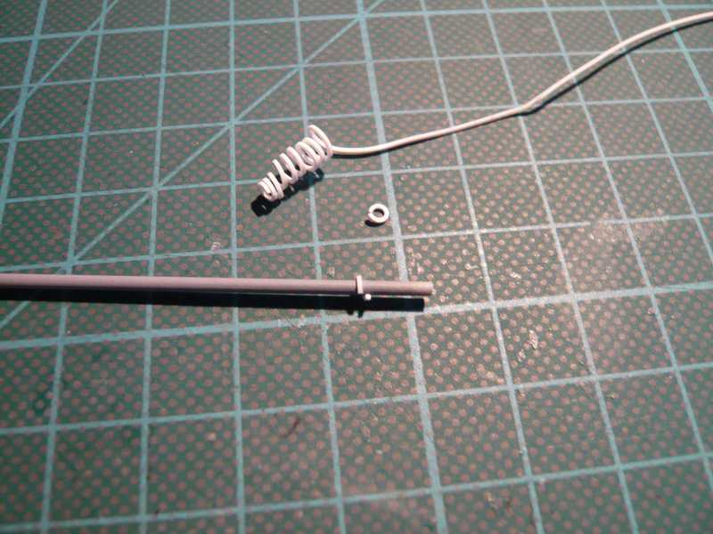 For the boot I used lead-wire 0.3 mm in diameter, which is wrapped and later glued to the 1.6 mm round profile of the vent line. A blank flange with a gasket ring for connection to the LOX-Vent line of the pad is located at the end of the line, I indicated by three small sheet slices. 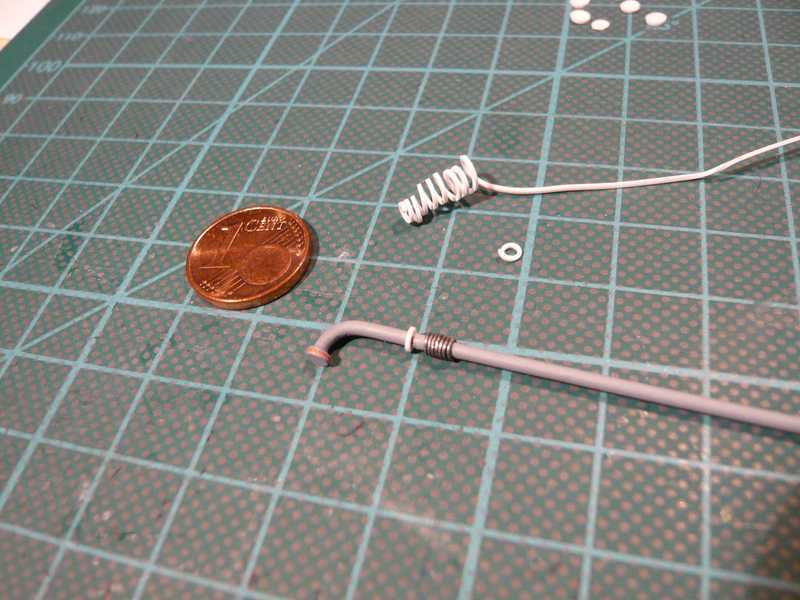 And so looks like the finished Expansion joint. 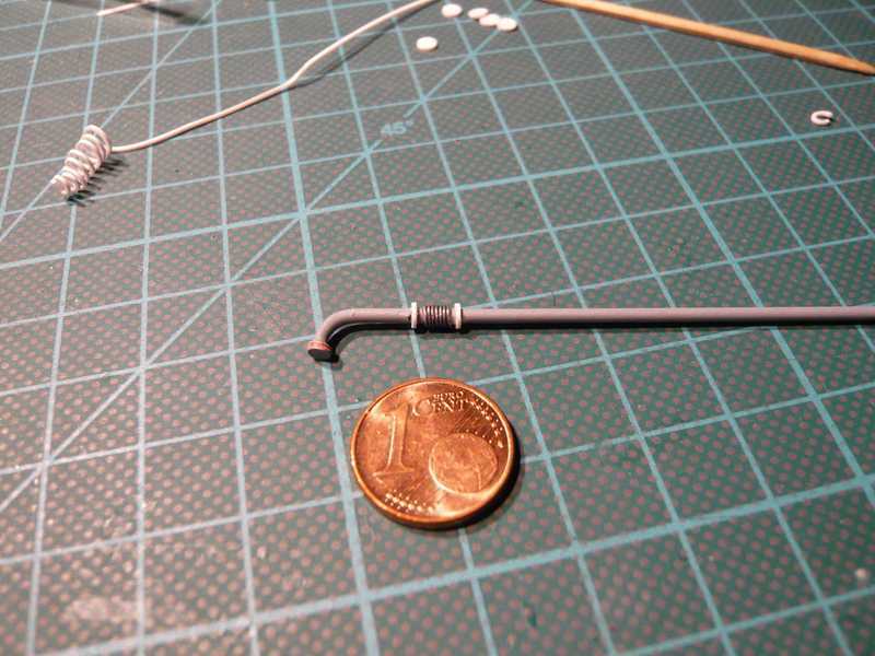 And at this point here next to the corner it is sitting, if it is painted.  And the other two expansion joints are manufactured according to the same procedure, only I have twice split the line for the installation and after insertion of the segments then reconnect, otherwise not go but unfortunately.
__________________
Greetings from Germany Manfred Under construction: Launch Pad 39A with Challenger STS-6 (1:144) Last edited by spacerunner; 10-12-2016 at 04:40 PM.
|
|
#90
08-25-2013, 12:58 AM
|
||||
|
||||
|
As the LOX-Vent line on the Side 2 total has three expansion joints and that next just behind the corner of Side 1 is followed, so a few pieces had to be prepared in the same way as before.
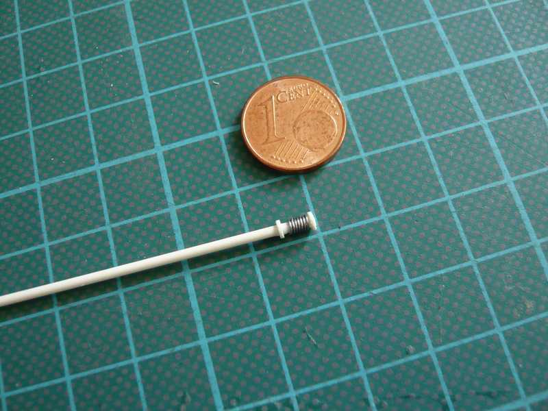 And in the meantime a shift-work in the paint shop was due then also once again, with some pipes and the pipe supports for the left pallet on Side 1 were painted.  Since unfortunately little can be seen by the odds and ends on this photo here are again a few other pics.  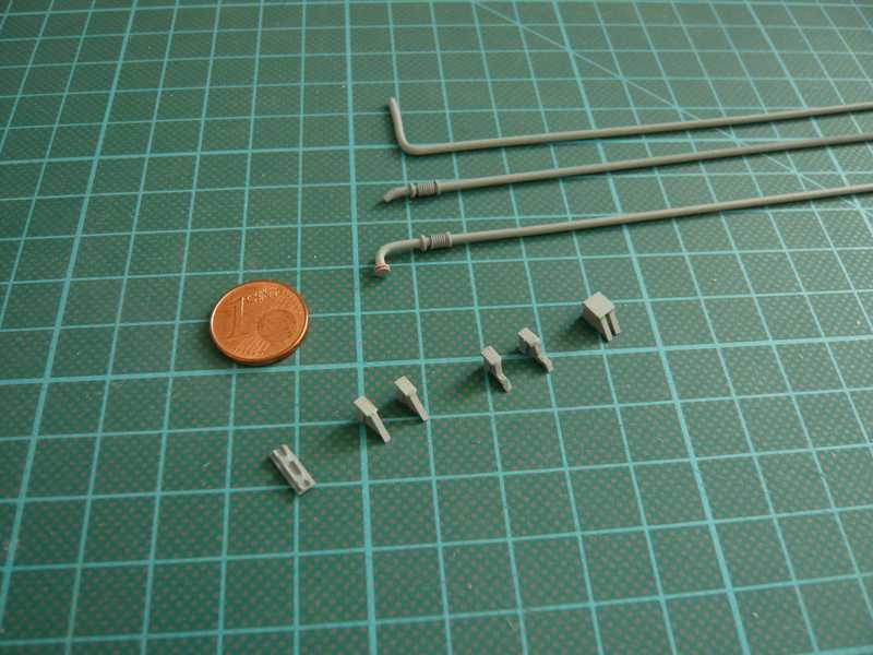 The small part on this photo left in addition to the pipe supports for the Side 1 should be a Pipe anchor be coming as a support in addition to the central expansion joint of Side 2, as this somewhat less stable pipe areas are each additional fixed. And now the first part of the Vent line at the rear end of Side 2 could be installed at last. To build the second expansion joint in Bay 13, I had to cut the vent line there unfortunately.  From here, I then have pitched a further piece of line with an expansion joint (see photo 1) through the pipe supports forward out and both glued carefully with each other, which is hard to see. This second piece is running up into the Bay 1, where the third expansion joint sits, which then can be glued to, whether with or without the line bow around the corner I must consider me still. From here, I then have pitched a further piece of line with an expansion joint (see photo 1) through the pipe supports forward out and both glued carefully with each other, which is hard to see. This second piece is running up into the Bay 1, where the third expansion joint sits, which then can be glued to, whether with or without the line bow around the corner I must consider me still.  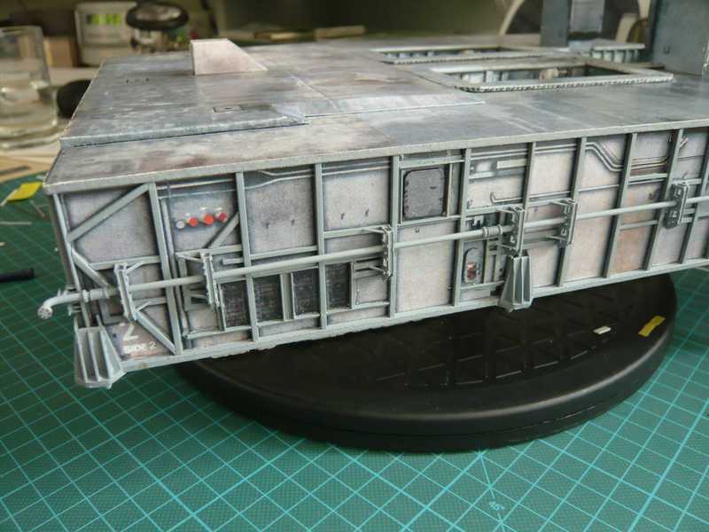 The procedure is admittedly somewhat circuitous, but unfortunately not avoided. And then still the pipe anchor came on his place left in addition to the central expansion joint. 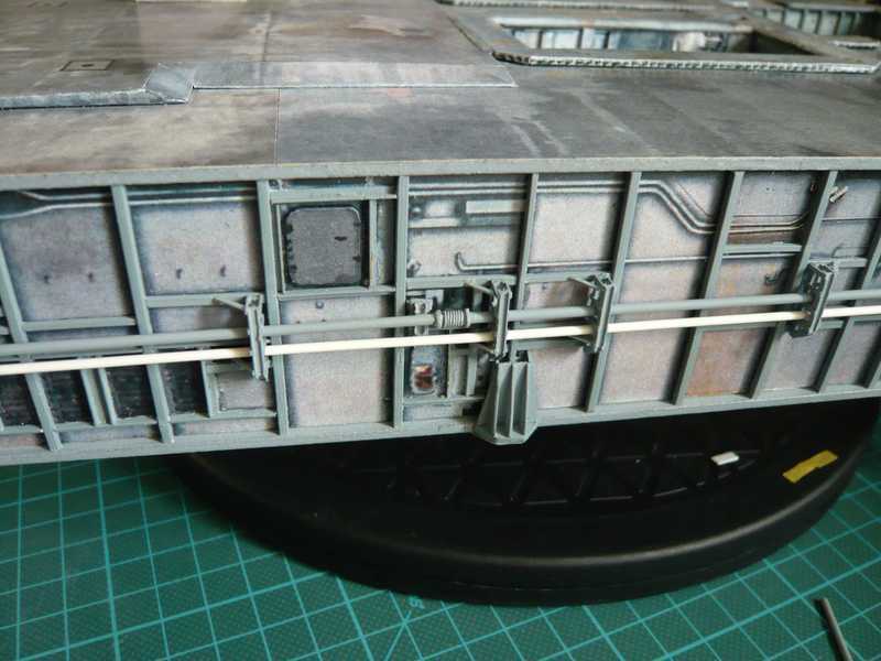 The white LOX-Transfer line is inserted so far only provisionally and is supposed to get a few details. I consider only whether I should still paint the line with white color, or if I leave it as it is, what do you think?
__________________
Greetings from Germany Manfred Under construction: Launch Pad 39A with Challenger STS-6 (1:144) Last edited by spacerunner; 10-12-2016 at 04:41 PM.
|
| Google Adsense |
 |
|
|


 Linear Mode

