


|
|
|
#891
 10-03-2015, 05:03 PM
|
||||
|
||||
|
Sorry guys,
I have confounded the picture,  this is the correct picture. this is the correct picture. 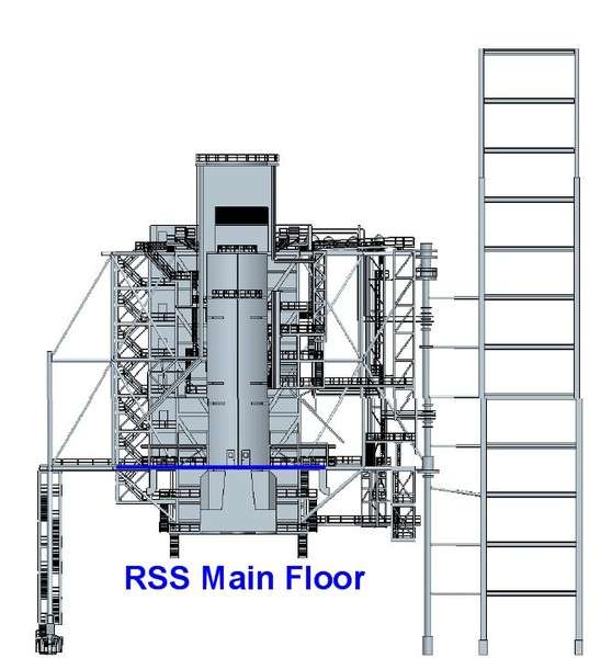 
__________________
Greetings from Germany Manfred Under construction: Launch Pad 39A with Challenger STS-6 (1:144) Last edited by spacerunner; 09-25-2016 at 04:48 PM. 
|
|
#892
10-03-2015, 05:10 PM
|
||||
|
||||
|
Hi everybody,
once again, the staircase in front of the elevator shaft, which LVM has constructed incorrectly, actually even falser than Revell, if you look at it closely, what I want to clarify here again. The Revell stairwell has in the lower and upper part (above the RSS main floor), in each case four floors, what is one too many in the upper part because there are only three floors there.  The LVM stairwell, however, is correct in the upper part with three floors, but wrong in the lower part with only three floors. The correct solution would be a superimposed arrangement with the Revell solution in the lower part and the LVM solution in the upper part, because then the stairwell would actuallyhave seven floors in the correct arrangement.   The question remains, how to solve the problem ...  Therefore, one should actually require a rework by LVM, in view of the money, what the kits have cost.  Then It would have been better if they had left it at the reproduction of the Revell stairwell, in which then at least the lower part would have been correct. 
__________________
Greetings from Germany Manfred Under construction: Launch Pad 39A with Challenger STS-6 (1:144)
|
|
#893
10-04-2015, 02:40 AM
|
||||
|
||||
|
It's really complicated, I hope that you can find out a good solution for your magnificent project!
|
|
#894
10-04-2015, 08:02 AM
|
||||
|
||||
|
Hi everybody,
after further research also the local conditions in the gap behind the RCS Room have further clarified.  The HER has the following dimensions, length (north-south) 36' (10,97 m), width 28' (8,53 m), height 14' (4,27 m) and is thus slightly higher than in my previous basic sketch, which looks something like this. 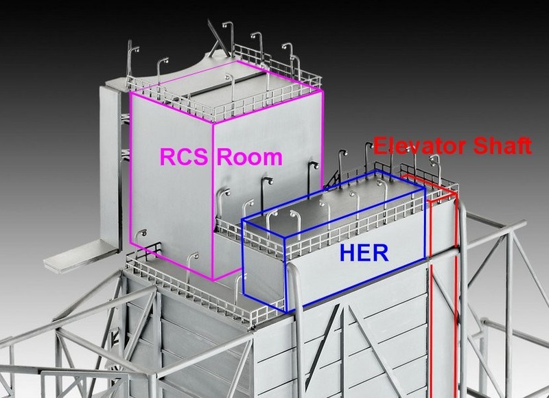 Here is another view of the gap between the RCS Room and HER. On it one see that there is still an anteroom located in front of the HER, which is slightly lower and shorter and fills about half of the intermediate space. Out of it at the top a cable duct leads into the RCS Room. 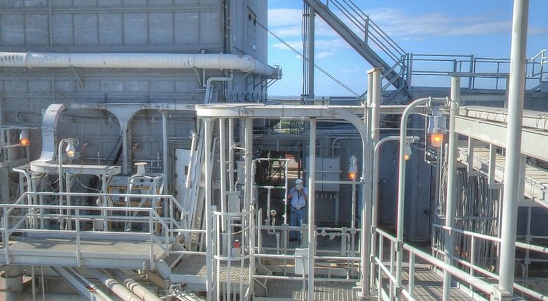 Source: NASA This drawing should illustrate this something. 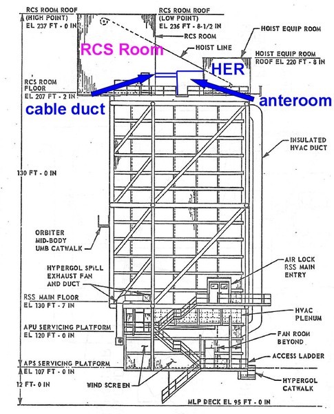 Source: capcomespace.com The interesting question for me was now again, whether this at the time of STS-6 already looked like that, because some rooms on the RSS have been installed only later, such as on the west and south sides of the RSS Main Floor behind the PCR.  Therefore I was glad that I have found after a long search this old black and white photo here from 11/06/1980, which proves that it at the time actually already gave this anteroom. 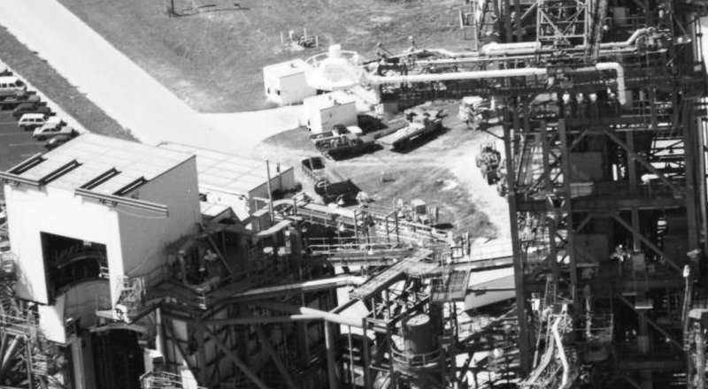 Source: NASA And here still for comparing the present state from a different point of view. 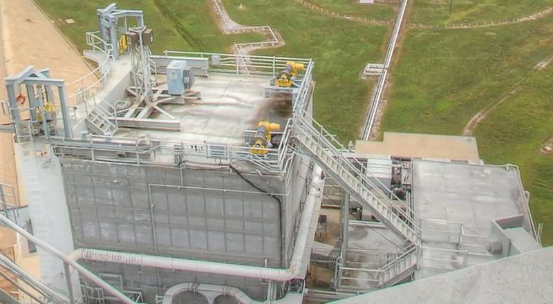 Source: NASA In order nothing stands in the way for an appropriate reconstruction of the RSS. 
__________________
Greetings from Germany Manfred Under construction: Launch Pad 39A with Challenger STS-6 (1:144)
|
|
#895
10-04-2015, 04:21 PM
|
||||
|
||||
|
Quote:
yeah, it's really a tricky and crazy matter, but I will struggle me through, you know me. 
__________________
Greetings from Germany Manfred Under construction: Launch Pad 39A with Challenger STS-6 (1:144) Last edited by spacerunner; 09-25-2016 at 04:49 PM.
|
|
#896
10-05-2015, 03:40 PM
|
||||
|
||||
|
Hello everybody,
after the front and side view I have now also drawn a plan view, which should help me especially with the planned modification of the RSS-rooms, and there was again a little surprise.  For a rough orientation this Streetview image of the Pad 39A was very helpful. 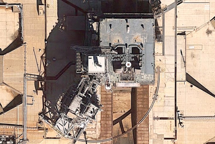 Source: google.de And this here is firstly the unchanged Revell arrangement where I intend to change both the PCR and the elevator shaft and HER and thus adapt more to the reality. 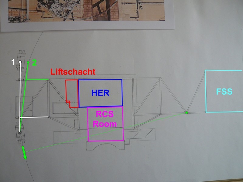 And after drawing in the truck rails arc, I noticed immediately that the rear truck (position 1) would stand next to the truck rails, what obviously can not be,  since I also still intend to plan a diorama. since I also still intend to plan a diorama. To put now the truck from position 1 to 2 on the truck rails, you could now easily put the outer support frame at a slight angle under the support structure, what would then surely look modestly because of the supernatant. Since I was first surprised, I checked the disassembly plans, and thereafter the outer support frame (line 7) is actually slightly inclined backwards, which I had not observed so far. 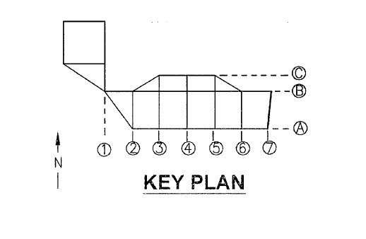 Source: NASA Here are the two supporting frame components with dimensions, part 45 is the front frame, the rear is part 46, both of which have the same structure, which is not correct.  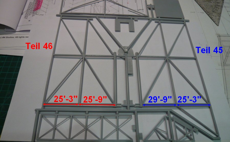 As one can see, the difference is 4' (1.22 m), which corresponds about 7 mm (1:168). Strictly speaking one would intervene in the supporting structure and extend the outer raster of the front frame (part 45) what would be absolutely feasible.  But since these two parts would have to be reworked anyway and are already on the to-do list, 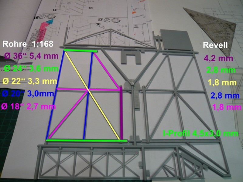 which could then be done the same in one go. 
__________________
Greetings from Germany Manfred Under construction: Launch Pad 39A with Challenger STS-6 (1:144)
|
|
#897
10-15-2015, 08:51 AM
|
||||
|
||||
|
Hello everybody,
thanks to my friend James MacLaren from the NASASpaceFlight Forum who knows the Pads 39A/B very well, I have now a little more clarity on what profiles were used for the already discussed horizontal and vertical lattice structures on the PCR walls, which I have highlighted in this drawing.  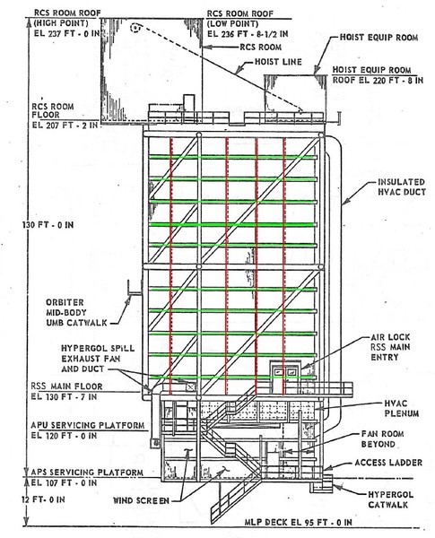 Source: capcomespace.com These girts (green) in the horizontal lattice structure directly on the walls are apparently W12 beams (Wide Flange Beams), and the vertical lattice structure between them is constructed using W6 beams (red). 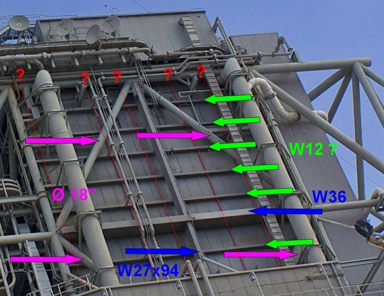 Source: NASA In this view, the arrangement of the profiles is even clearer to see. 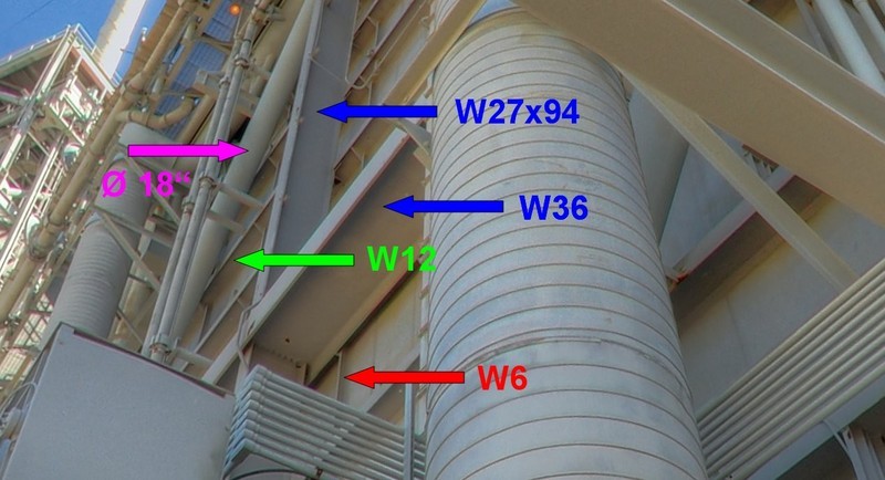 Source: NASA Next, I will deal again closer to the elevator shaft and the HER.
__________________
Greetings from Germany Manfred Under construction: Launch Pad 39A with Challenger STS-6 (1:144)
|
|
#898
10-15-2015, 03:21 PM
|
||||
|
||||
|
Ok, now I am beginning to think; that this whole model, when complete, is gonna be fully functional; and your next build thread is gonna be a fully functional shuttle/boosters/tank combination to fit.
 With the amount of attention to detail you display, well, I cannot think otherwise.... I love this thread! BLAST OFF!!!!! 
__________________
Once a King, Always a King. But, once a Knight is enough!
|
|
#899
10-15-2015, 04:21 PM
|
||||
|
||||
|
Thanks Dan for your kind words, but that would be overkill.
__________________
Greetings from Germany Manfred Under construction: Launch Pad 39A with Challenger STS-6 (1:144)
|
|
#900
10-16-2015, 05:22 AM
|
||||
|
||||
|
Hi guys,
as you can see in the photos of of the dismantled RSS on Pad 39B everything much clearer, here is a last clarification to the stairwell next to the lift shaft. 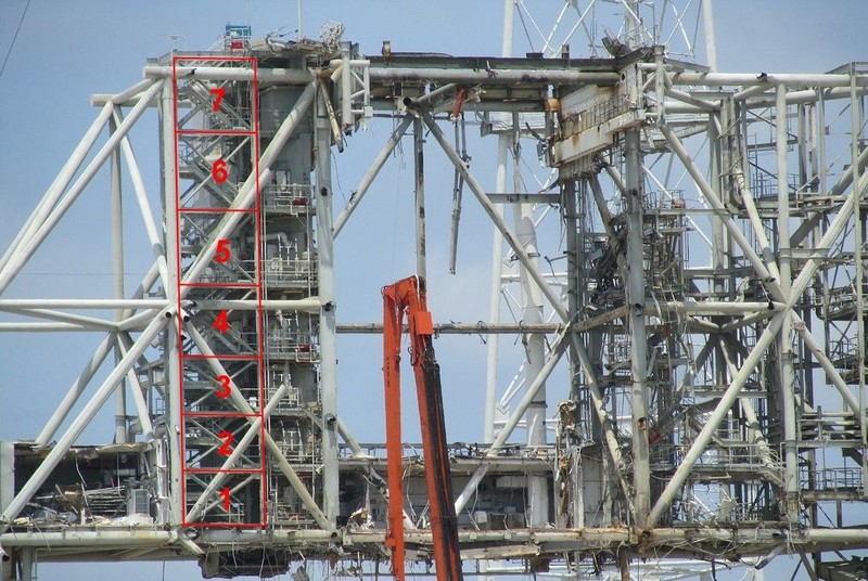 Source: flickr.com (Andrew Scheer) As you can quite clearly see here, the stairwell above the RSS Main Floor, actually has seven floors, and not six as with LVM. But they are not arranged uniformly distributed over the total height of the frame structure.Rather, the bottom three floors have approximately the same height, and also the top three, whereupon whose height is slightly larger. The 4th floor is slightly lower than the upper three and goes out about the central transverse brace of the frame structure, like the 7th floor something goes over the upper transverse brace addition. Whether this finding, however, would now convince LVM thereof, to modify their stairwell accordingly, remains pure speculation, it would be welcomed in any case.
__________________
Greetings from Germany Manfred Under construction: Launch Pad 39A with Challenger STS-6 (1:144)
|
 |
|
|


 Linear Mode

