


|
|
|
#2751
 01-20-2023, 06:40 PM
|
||||
|
||||
|
Hello everybody,
well then let's get to the tricky Double-angle holders, on which the Worm Gears are mounted, which I've cut with the Chisel cutter from my prepared H Profile to 1,7 mm length.  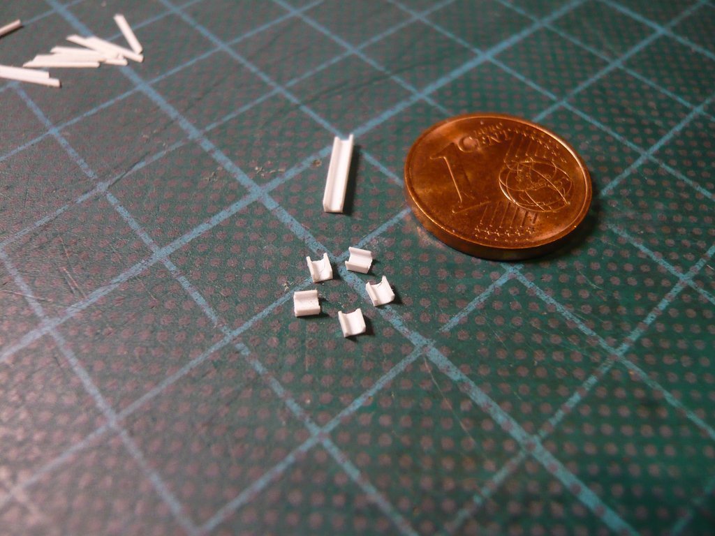 However, since the shape of the sides of the angle is not an isosceles triangle, as can be seen in this image,  Source: NASA (STS-125) I first had to attach these unequal slants to both sides of the tiny one, which was quite difficult because one can hardly fix the angle for it, but I managed to do this to some extent with the cutter and careful sanding.  Then the Screw Jack protective tube (Ø 0,5 mm x 9,5 mm) could be glued at the underside of the angle, aligned and set aside to dry, Then the Screw Jack protective tube (Ø 0,5 mm x 9,5 mm) could be glued at the underside of the angle, aligned and set aside to dry, 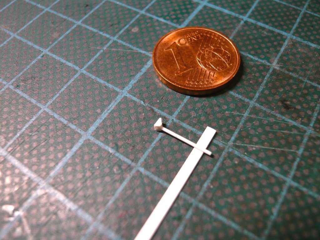 which did complete the bottom half of the first Screw Jack.  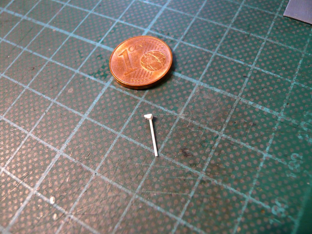 And so to the Folding Bellows sitting on the top of the angle, which I had been racking my brains about for some time.  After careful consideration, I have now decided on the variant with insulating tubes of different thicknesses, with the lower part (Ø 1,4 mm x 1,5 mm and the part above (Ø 0,6 mm x 1,0 mm).  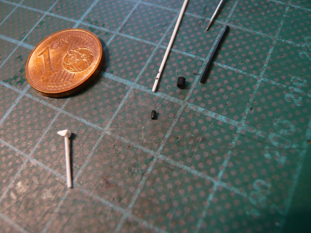 While pushing the thicker part onto the round rod (Ø 0,5 mm) did not cause any problems, I've first widened the thinner part with a pin (Ø 0,5 mm), although pushing it onto only succeeded under hot water.  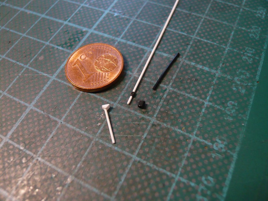 And this bellows with the coupling rod now still had to be glued to the tiny Worm Gear (Ø 1,0 mm x 1,0 mm), to which I before still had to attach the Shaft Housing ( 0,5 mm x 0,5 mm x 1,5 mm). 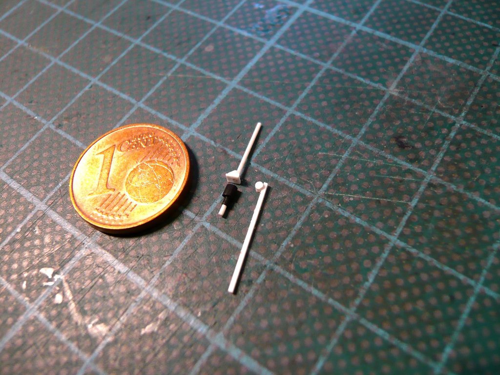 This gear unit was then still glued to a small base plate (0,13 mm x 1,4 mm x 1,5 mm), 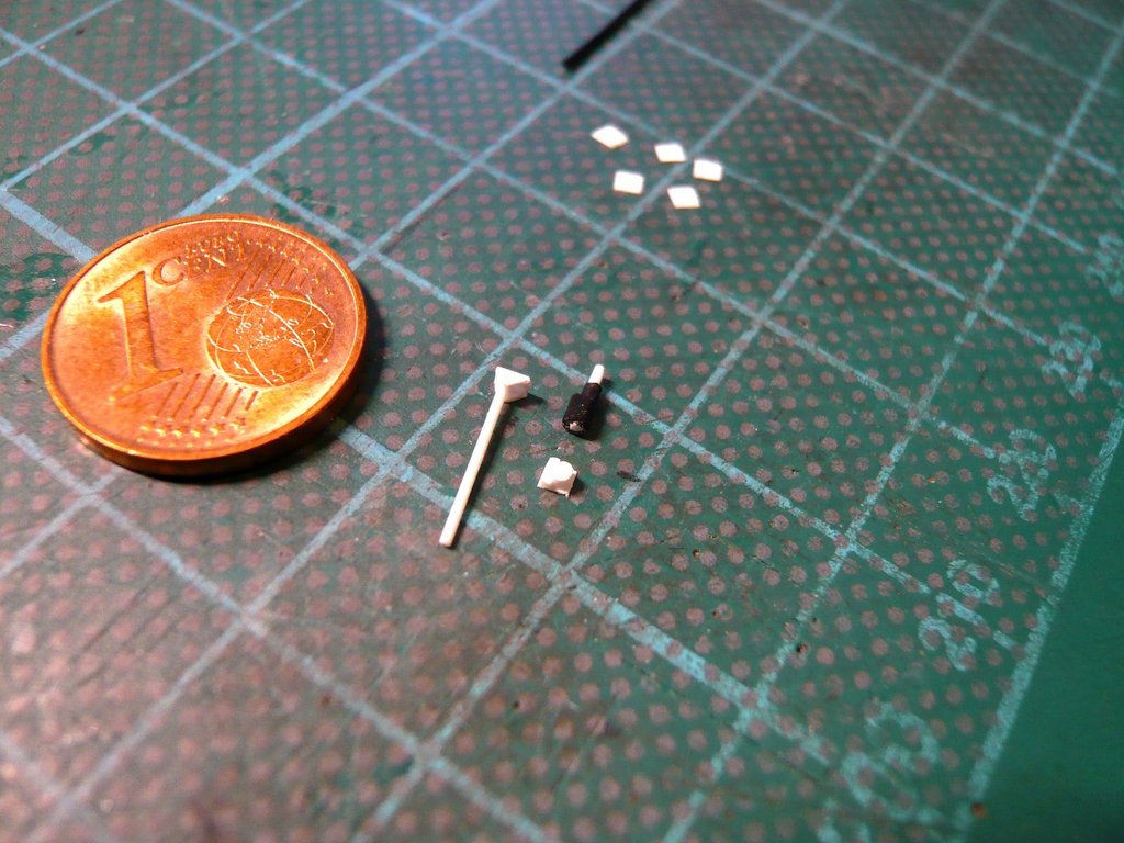 which shows that it is meanwhile about tenths of a millimeter.  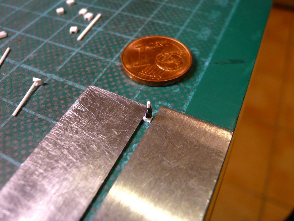 Before gluing both parts together, I still wanted to determine the exact position of the Screw Jack on the still to be built frame platform, 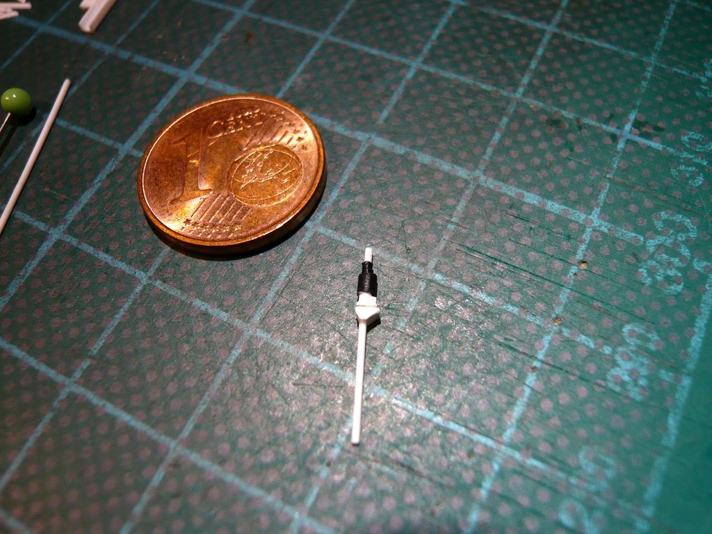 since the position of the Shaft Housing must match that of the Bevel Gearbox of the door drive, between which the tubes of the Output Shaft are running, like one can see in this photo.  Source: NASA (STS-135)
__________________
Greetings from Germany Manfred Under construction: Launch Pad 39A with Challenger STS-6 (1:144) 
|
|
#2752
01-20-2023, 06:41 PM
|
||||
|
||||
|
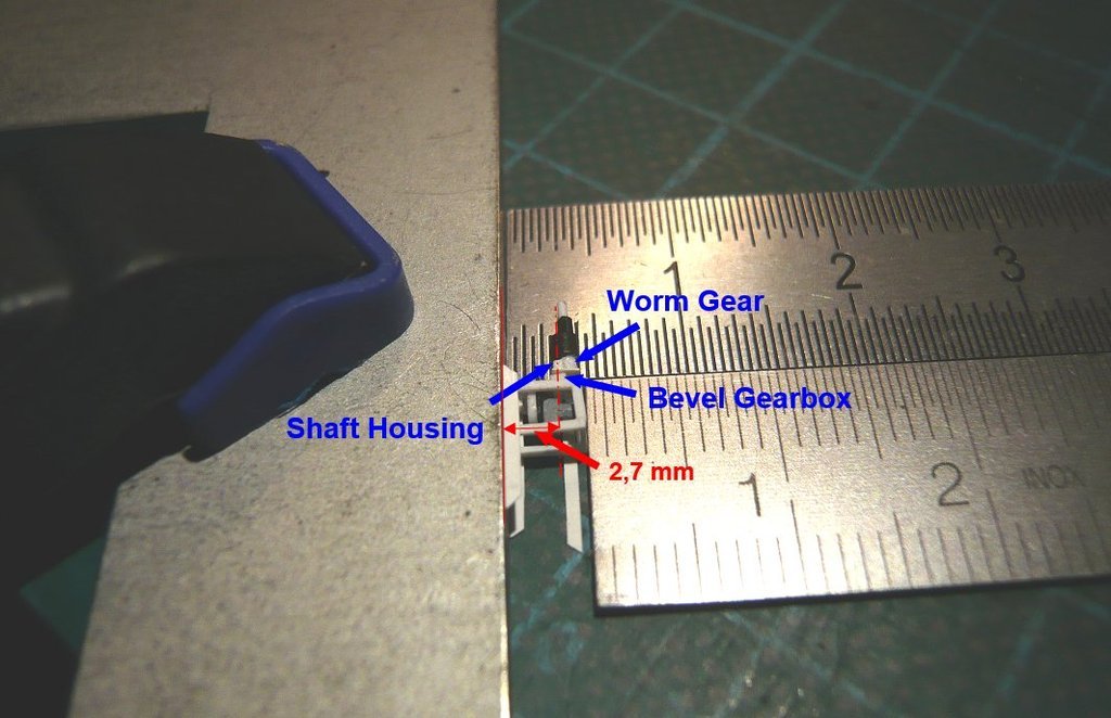
For this purpose, I placed the gear unit with the bellows on the finished door drive in such a way that the center line of the Worm Gear and the Shaft Housing are matching, what was resulting in a distance from the wall of the canister of 2,7 mm, which I have to take into account when gluing the screw jack onto the frame pedestal so that both tubes are running aligned later.
 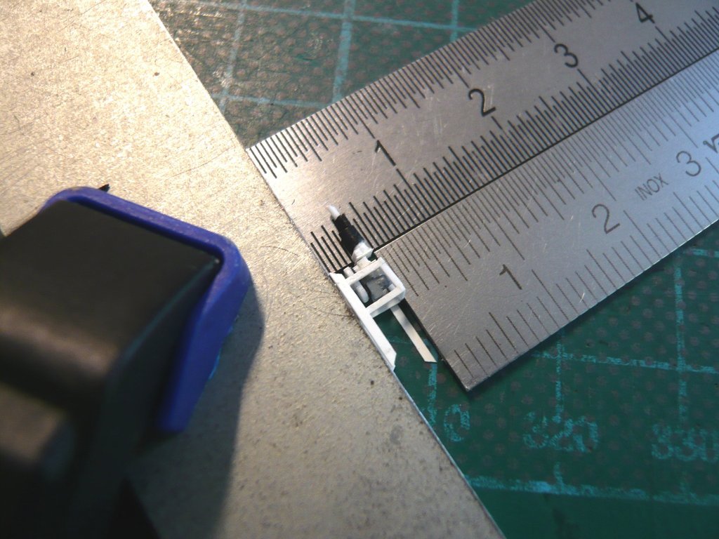 Then I started scratching the upper frame by gluing the prepared struts (0,25 mm x 0,5 mm) together, what resulted to a frame 2 mm x 4 mm. 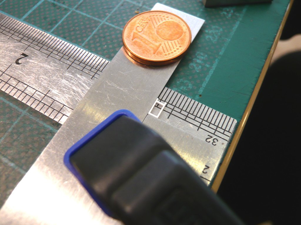 As one can see, the width of the screw jack base plate matches the width of the frame well. 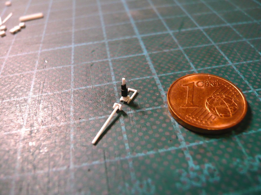 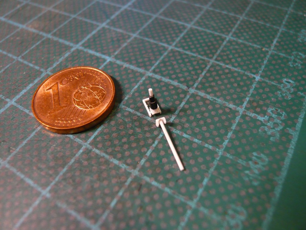 Here is an image to illustrate the size of the parts from the normal viewer perspective of approx. 30 cm.  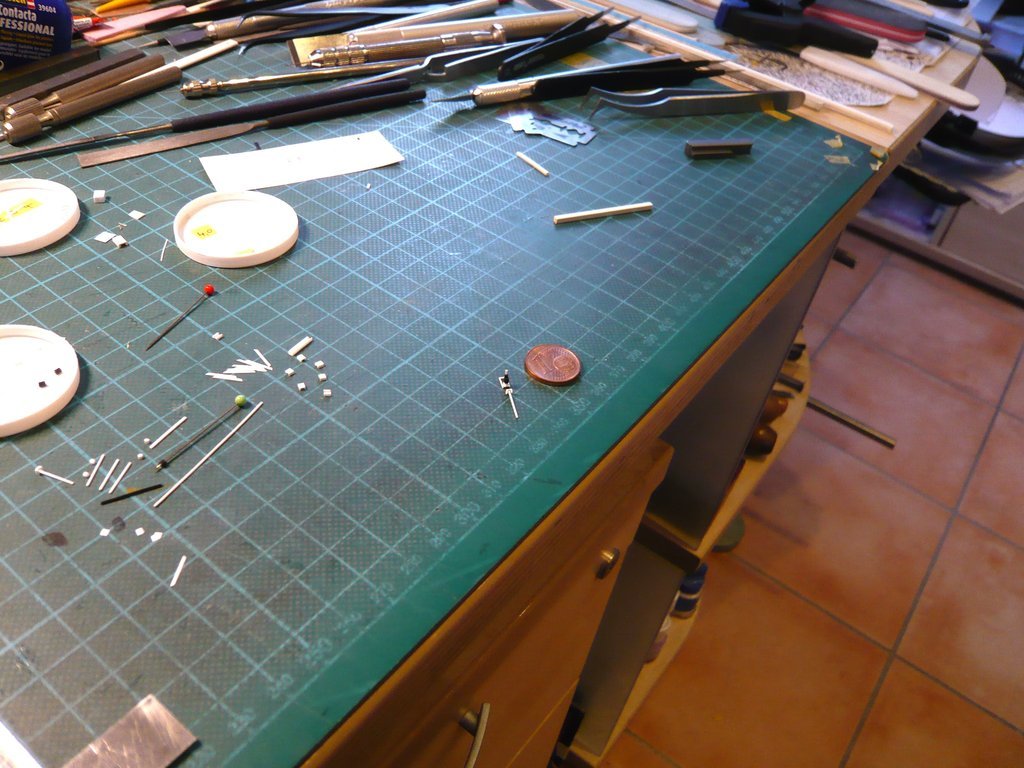 Next, however, the upper frame must first be completed with the remaining struts, because only then the complete Screw Jack can be glued onto it.  
__________________
Greetings from Germany Manfred Under construction: Launch Pad 39A with Challenger STS-6 (1:144)
|
|
#2753
01-23-2023, 07:58 AM
|
||||
|
||||
|
Hello everybody,
so let's continue with the remaining struts on the frame for the Screw Jack. 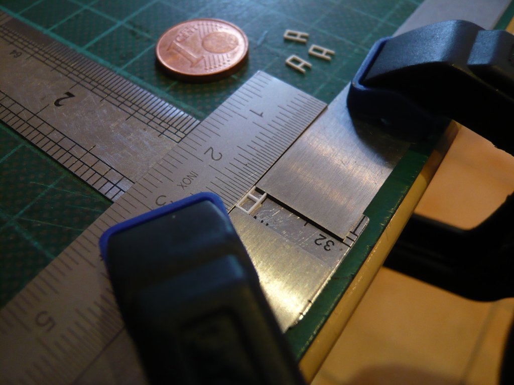 After all four top frames were done, 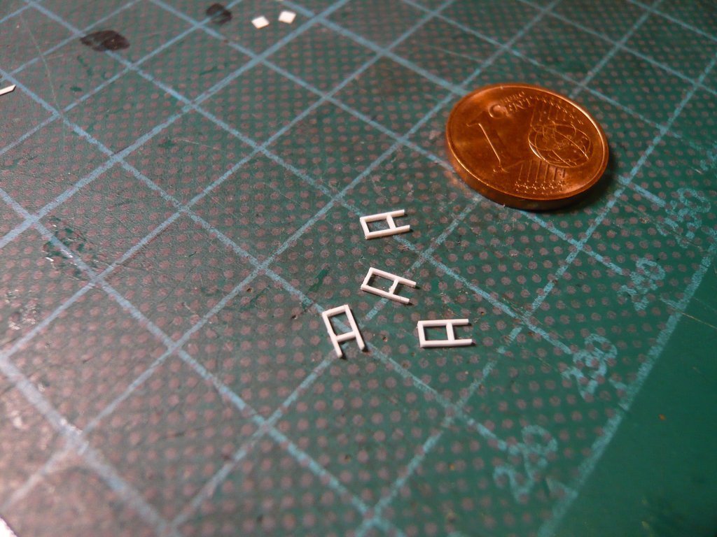 the vertical struts were glued, for which the frame had to be fixed again in order not to be able to slip, which can otherwise happen very quickly, 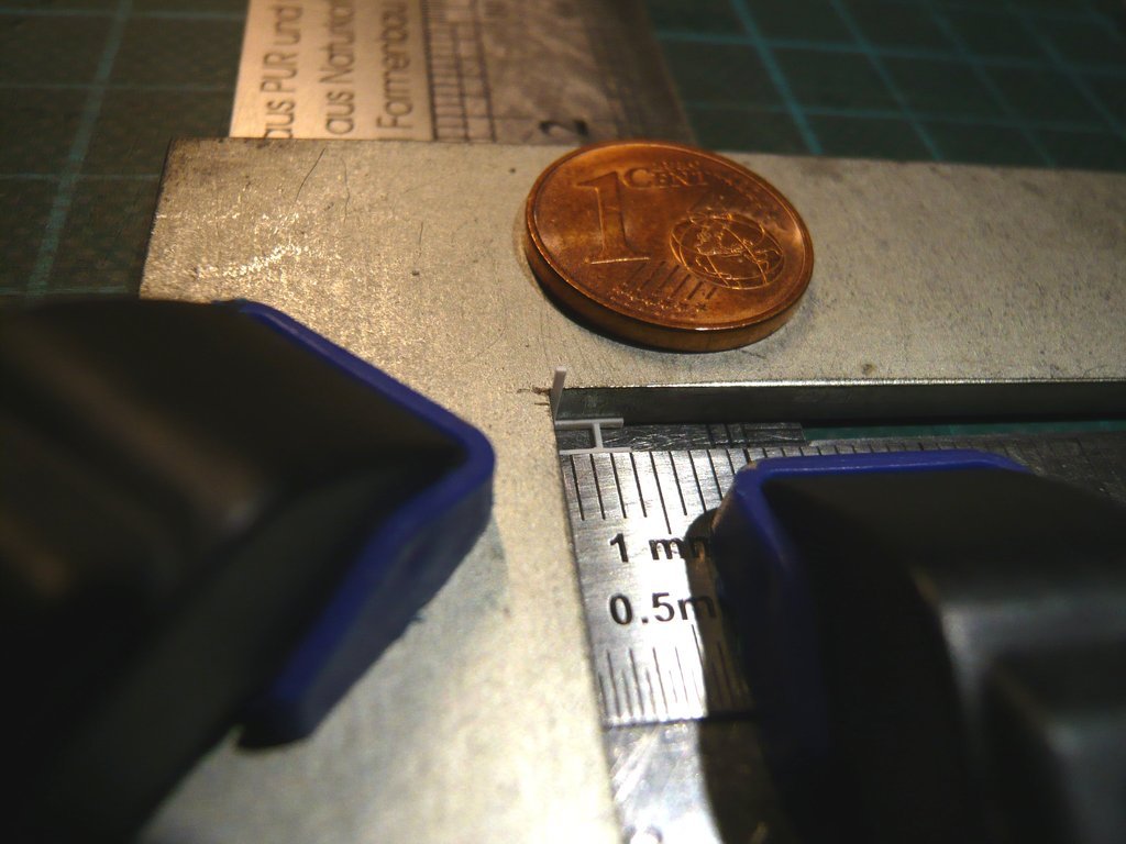 whereby had to be rechucked again and again.  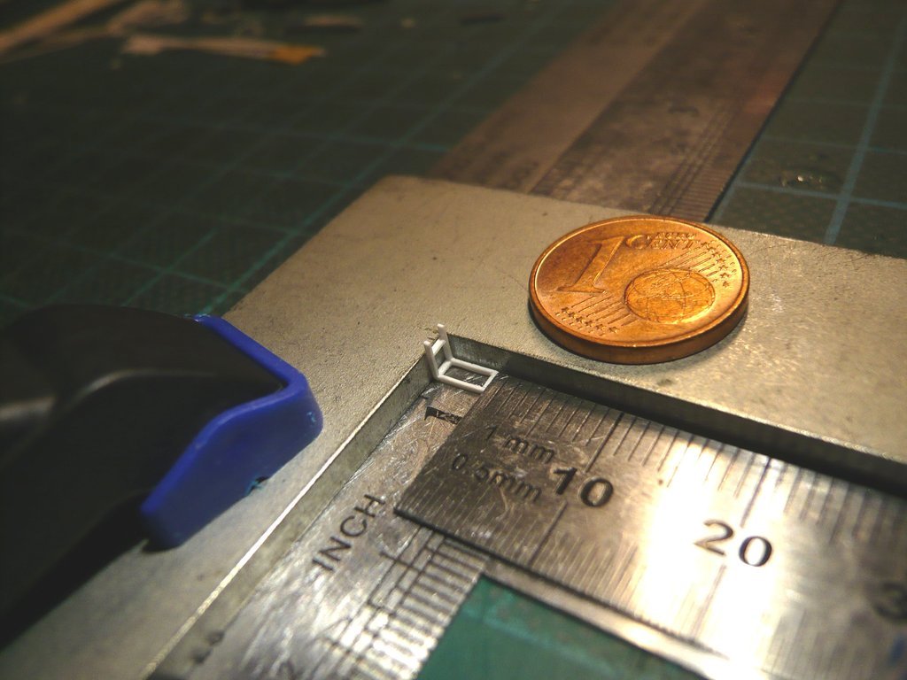 The test fitting on the sketch fits quite well so far, 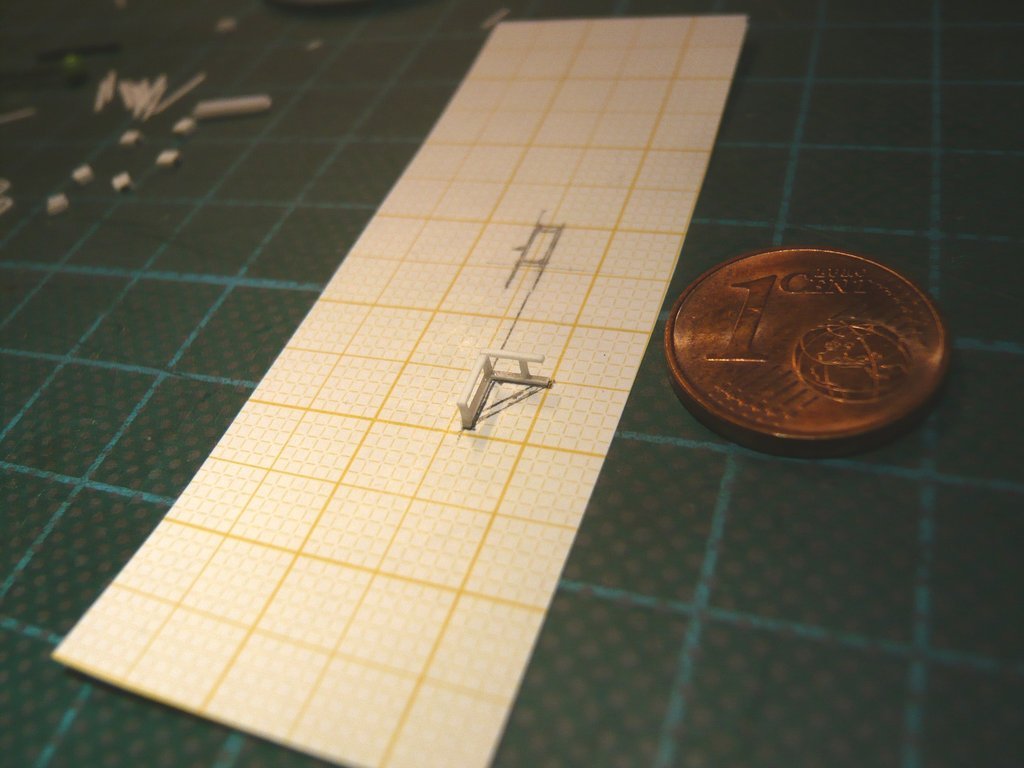 and the frame so far looks stable too. 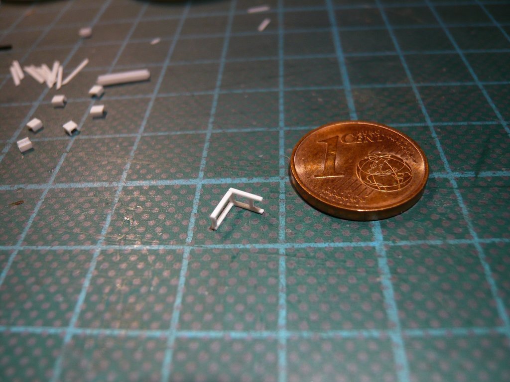 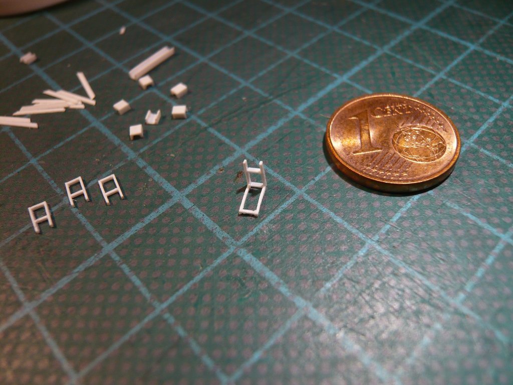 So it could now continue with the gluing of the diagonal struts, which were cut on this sketch. 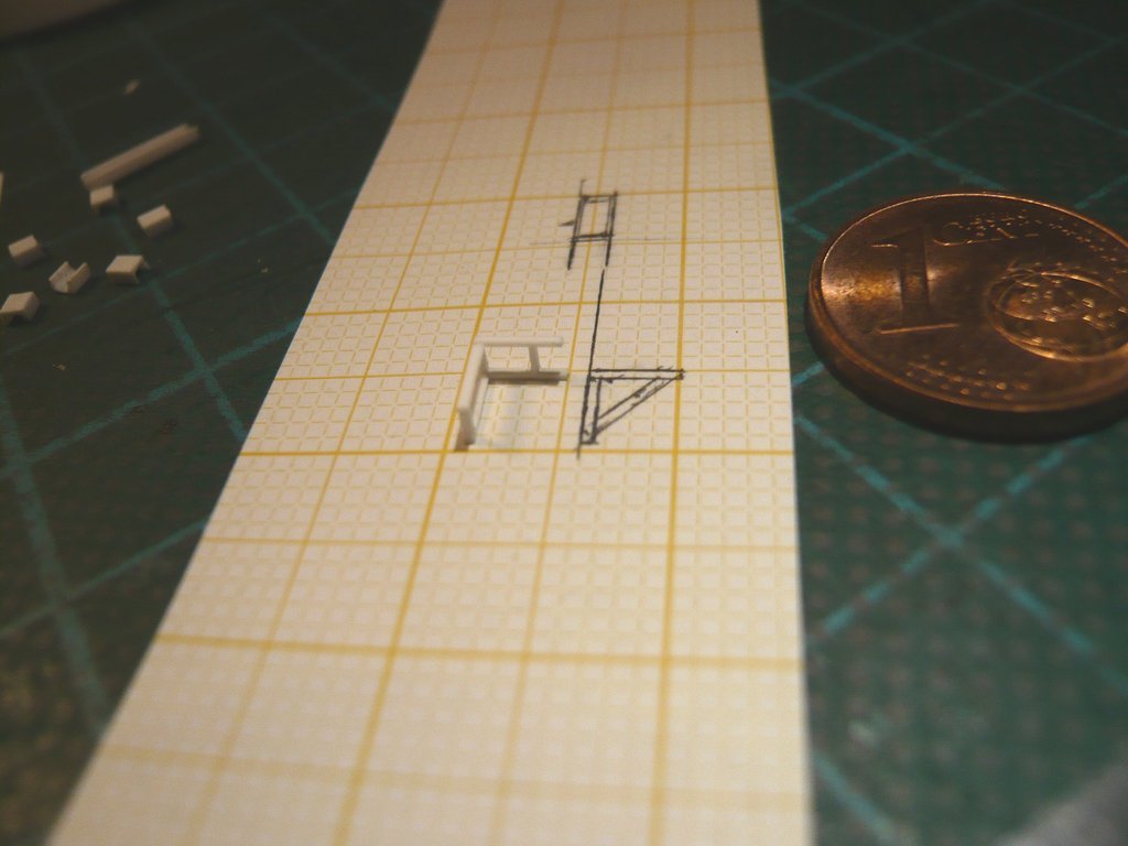 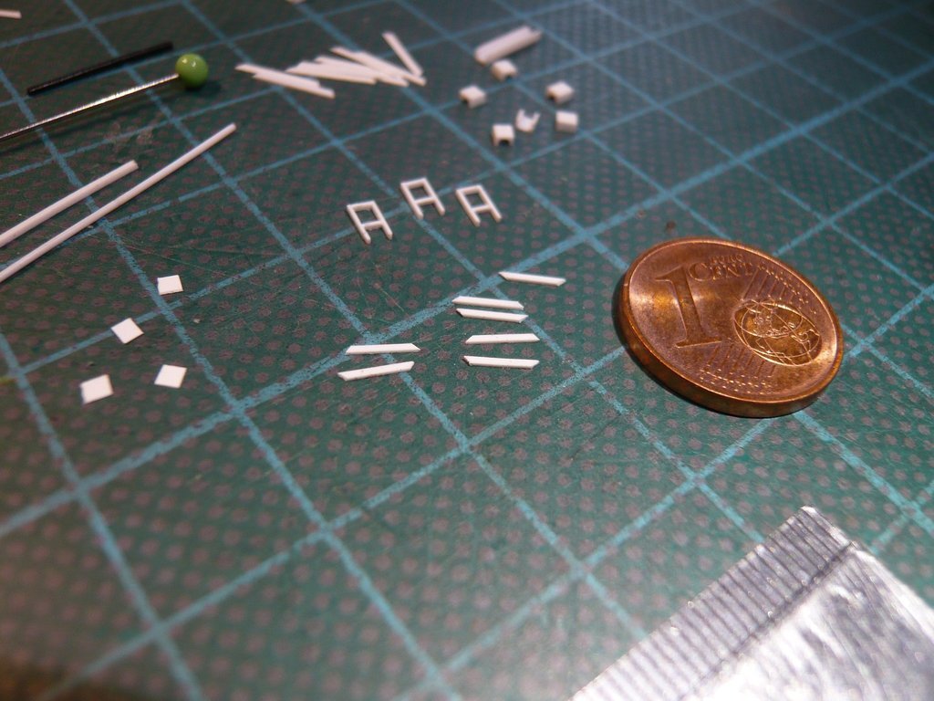 While the first strut could still be glued in relatively well after the appropriate fixation, 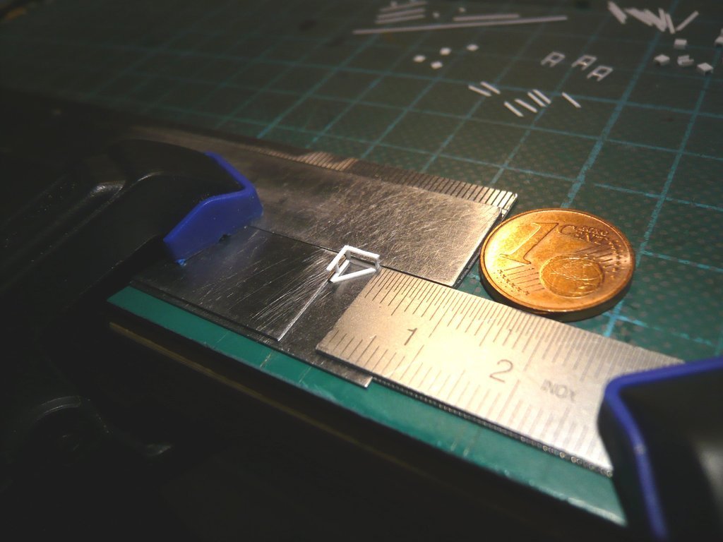 gluing the other strut was a bit more difficult, which is why the framework had to be fixed differently in order to have reasonably free access without the frame being able to slip. But I found a solution for that too.  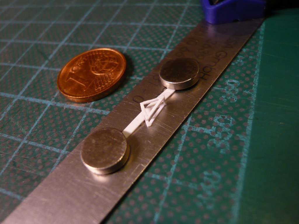 Now only the slightly longer struts had to be glued onto both long sides of the frame. 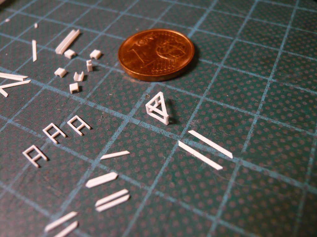
__________________
Greetings from Germany Manfred Under construction: Launch Pad 39A with Challenger STS-6 (1:144)
|
|
#2754
01-23-2023, 08:00 AM
|
||||
|
||||
|
For this I have adjusted the stop on the ruler in such a way that there is an overhang of 1 mm at the top,
 behind which I then glued the framework. 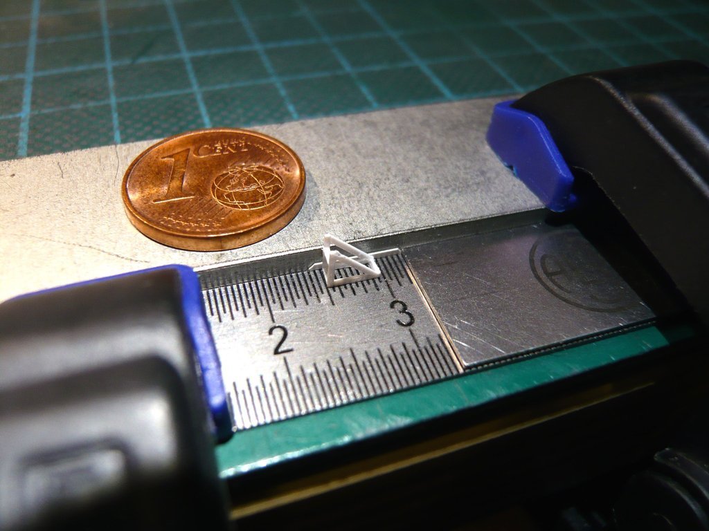 Then the strut was glued on the other side. 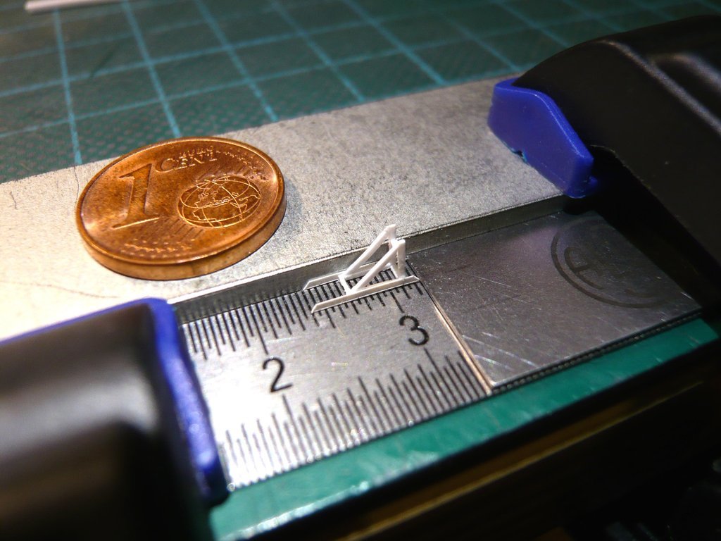 This was followed by a fitting on the Payload Canister, which was okay so far.  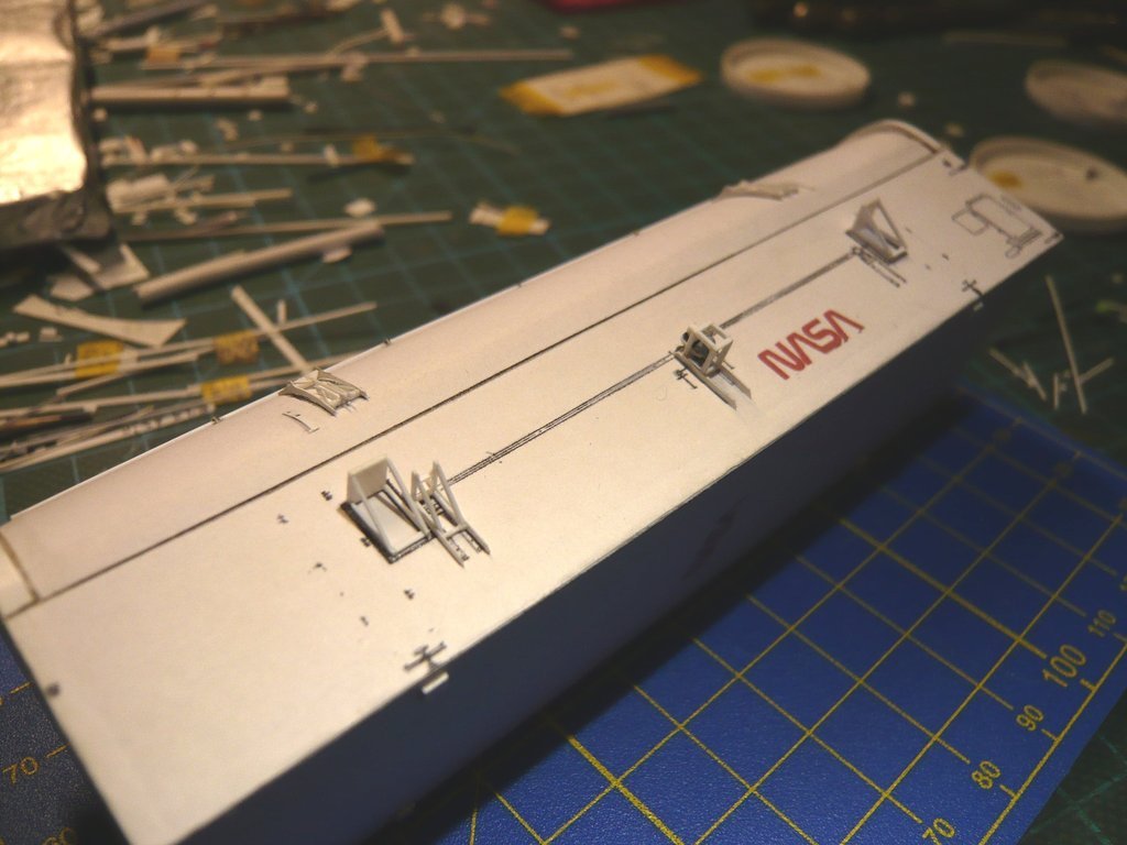 For gluing the Worm gear on the Folding bellows I first have tested the clamping option of the Protective tube with the Double angle holder and tested the seat of the gear. 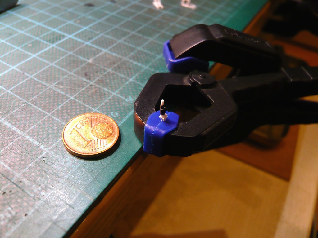 However, since I was not able to check the alignment of the protective tube with the upper spindle with this clamping and correct it if necessary, I decided to clamp into the scissor tweezers, which was clamped firmly on the table top. And thanks to my steady hand, the gluing of both parts worked right away, 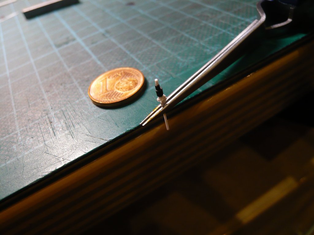 and the fit of both parts was also perfect. 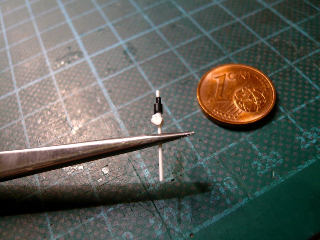 However, trying on the Screw Jack on the frame turned out to be a blatant number, since the clear opening of the frame and the width of the double angle holder with 1,5 mm are identical, causing the part kept slipping through. But on the 10th attempt it worked and stayed stable for a photo, which made up for the effort.  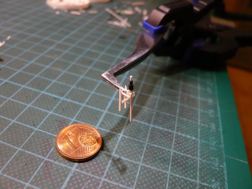 And that's exactly why the two small lateral holders must now also be attached to the double angle, but which are only 0,13 mm x 0,4 mm x 0,5 mm in size.   Source: NASA (STS-135) But I'm still trying to make it,  for which I have already found a suitable thin strip in my hodgepodge. for which I have already found a suitable thin strip in my hodgepodge. 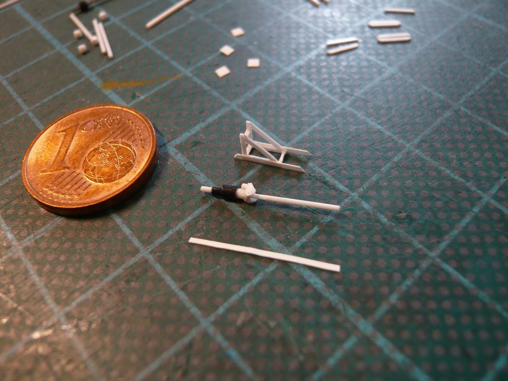 Let's wait and see.
__________________
Greetings from Germany Manfred Under construction: Launch Pad 39A with Challenger STS-6 (1:144) Last edited by spacerunner; 01-23-2023 at 11:55 AM.
|
|
#2755
01-25-2023, 09:16 AM
|
||||
|
||||
|
Hello everybody,
an exact re-measurement of the small angle holder on the double bracket of the Screw Jack resulted dimensions of 0,4 mm x 0,5 mm, which is why I did not use the initially selected 0,5 mm wide strip, as I would have had to cut 0,4 mm long strips from it, which is almost impossible to do it reproducibly.  So I've cut a new strip out of Evergreen Sheet Styrene (0,13 mm x 0,4 mm), although it was difficult to get the width (0,4 mm), which took me several attempts. This gave me the advantage that I could set the length (0,5 mm) on the ruler and only had to cut off the pieces. 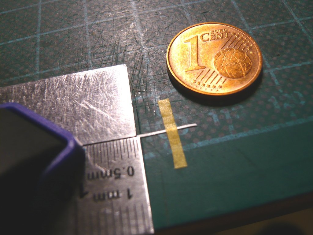 And now please buckle up!  These angle holders are by far the tiniest bits I've ever had in front of me to scratch, These angle holders are by far the tiniest bits I've ever had in front of me to scratch,  which I now somehow had to glue onto both sides of the double angle, which is why I was curious whether I would be able to do that at all. which I now somehow had to glue onto both sides of the double angle, which is why I was curious whether I would be able to do that at all. 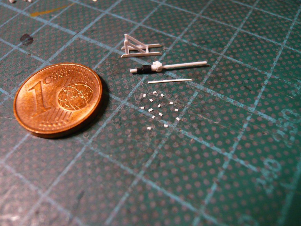 Here one can see that the snippet just about fits on the tip of the tweezers, but then really grabbing it, holding it and sticking it to the angle is almost impossible.  If at all, this only works with one of my patented Tape tweezers, who have often helped me in similar cases, hopefully this time too. Here I have already tapped and picked up the snippet with the tip of a new tape tweezers, and the acupuncture needle lays already in place to dab a tiny droplet of Revell Contacta-Professional onto the underside of the double angle. 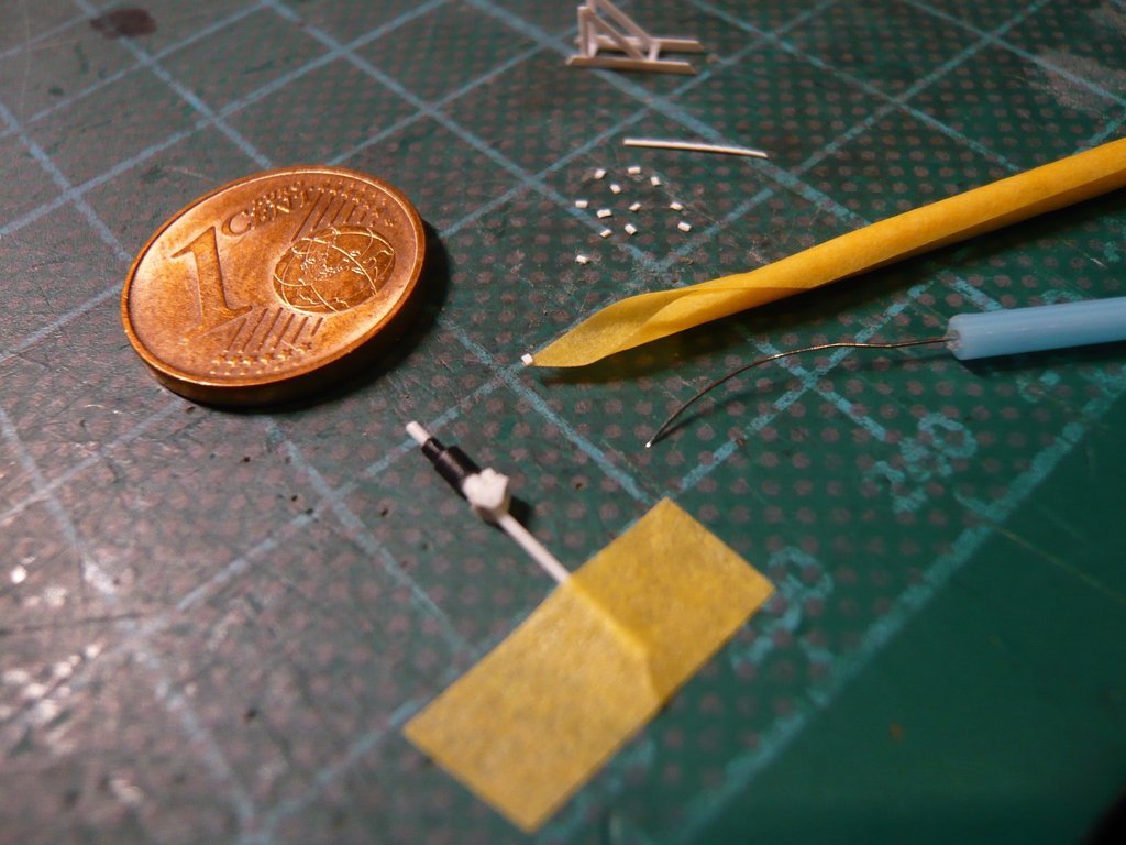 And here the first snippet is already glued, but you can hardly see it because these white plastic particles offer too little contrast, which is a well-known phenomenon with such macro shots. 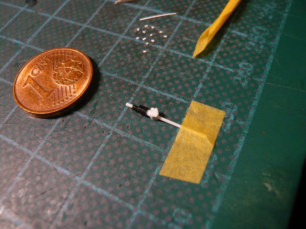 Maybe one can see it a little better on this shot, although it always depends on the incidence of light. 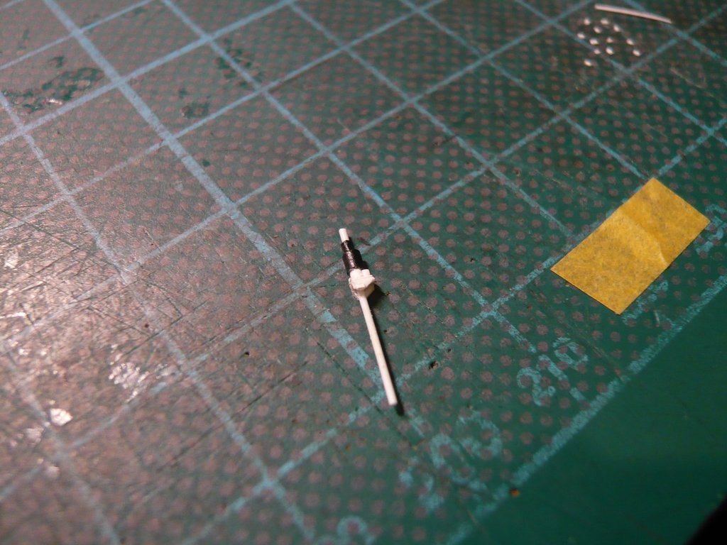 That's why I chose a lateral position here, where one can now see the midget relatively well. 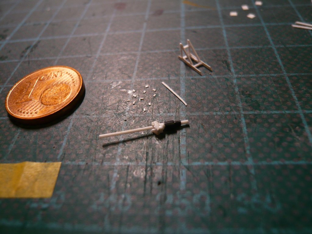 Then the angle holder was also glued to the other side, which resulted in a width of the double angle with these holders of 1,8 mm, which is actually enough to stand on the frame, which has a clear opening of 1,5 mm. 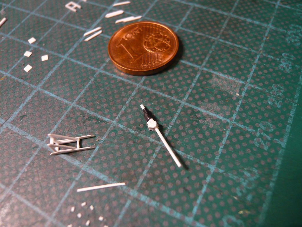 And after drying, the Screw jack was put to the test on the frame, what can be seen in this image, 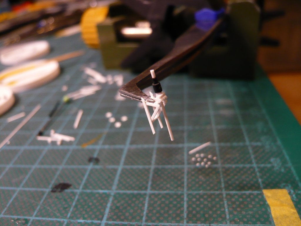 which has completely convinced me and so I could go to bed last night full of satisfaction ...
__________________
Greetings from Germany Manfred Under construction: Launch Pad 39A with Challenger STS-6 (1:144)
|
|
#2756
01-28-2023, 03:04 PM
|
||||
|
||||
|
Dear friends,
on this memorable day in 1986 with the Challenger Mission STS-51-L took place the first launch from the just finished Launch Pad 39-B,  Source: wikimedia.org which ended in a disaster 73 seconds after lift-off, in which the seven-person Challenger Crew lost their lives. 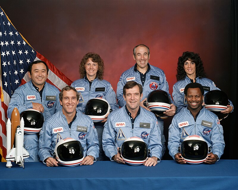 Front: Michael Smith, Francis Scobee, Ronald McNair; Back: Ellison Onizuka, Christa McAuliffe, Gregory Jarvis, Judith Resnik Source: wikimedia.org Let us take pause in silence and keeping their legacy alive forever.
__________________
Greetings from Germany Manfred Under construction: Launch Pad 39A with Challenger STS-6 (1:144)
|
|
#2757
01-30-2023, 05:51 PM
|
||||
|
||||
|
Hello everybody,
for the remaining three Screw Jacks I came up with a different solution.  In order not to have to glue the tiny Angle holders to the sides of the Double angle holder last, which was a pretty tricky affair, I have this step this time brought forward. That's why I first drilled the holes for the Spindle protective tubes in the brackets, first with Ø 0,3 mm pre-drilled, and then with Ø 0,5 mm re-drilled. Then the sides were beveled, 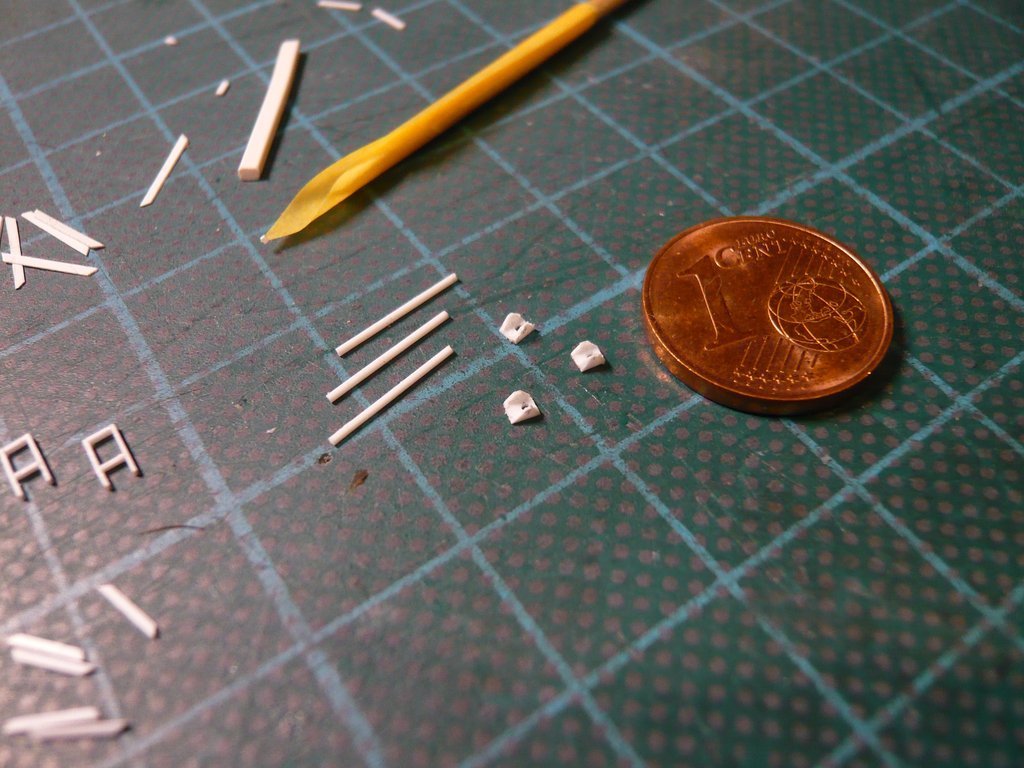 wherefore this time I fixed the holders between four rulers and then cut off the slants on both sides one after the other with a razor blade. And in this position I also glued the tiny angle holders onto the front side. 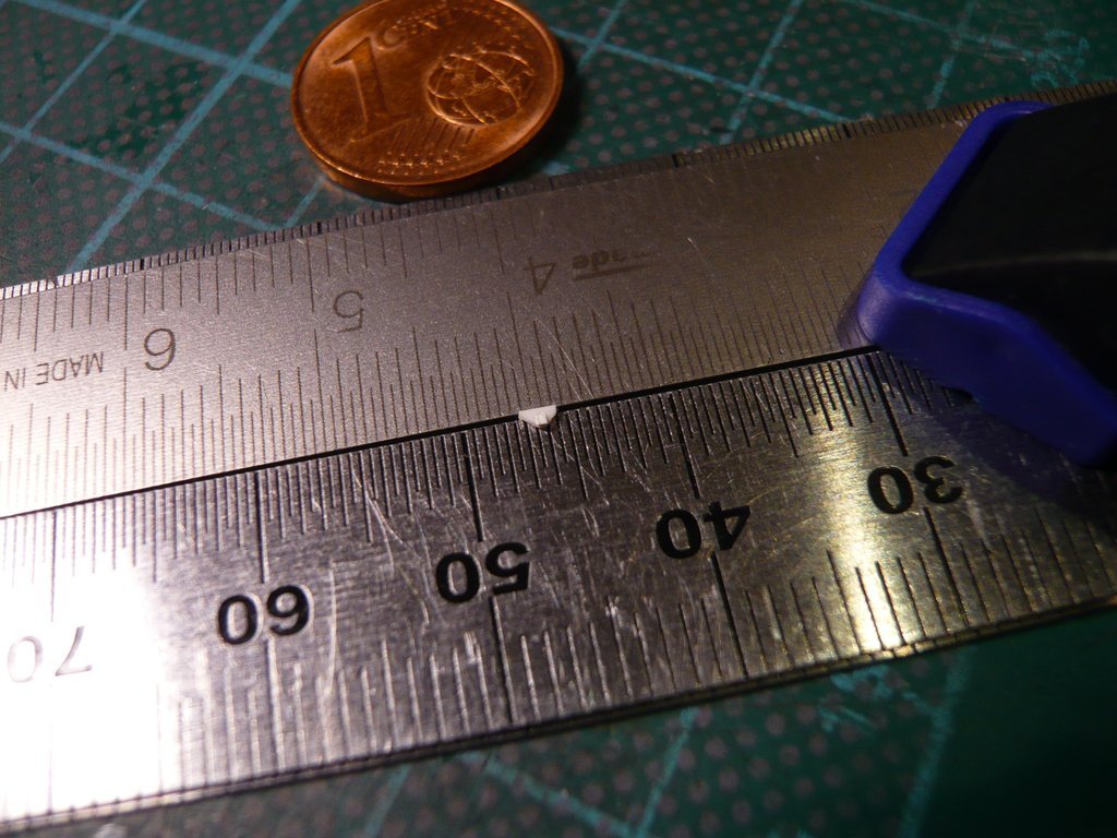 To glue the angle holders to the back, however, they had to be carefully re-clamped and precisely aimed with the tiny one on the Tape tweezers. 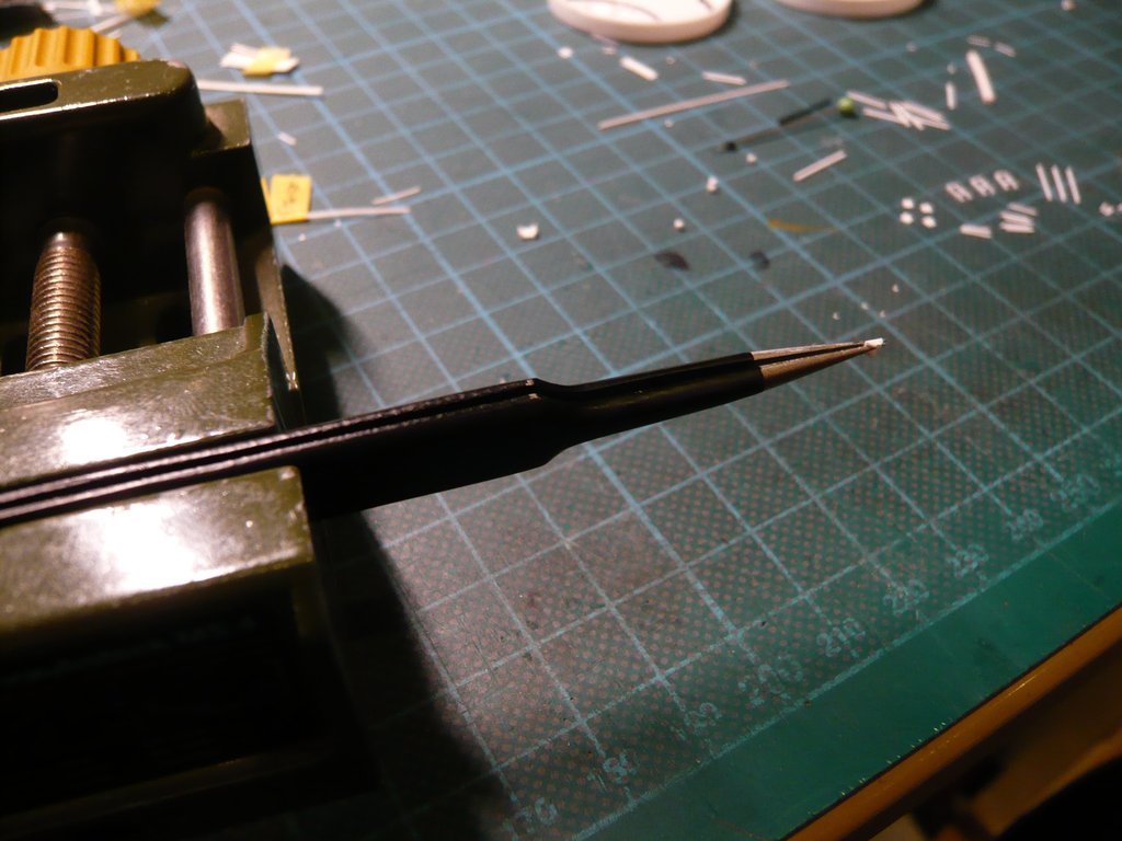 But now the Double angle holders are finished, 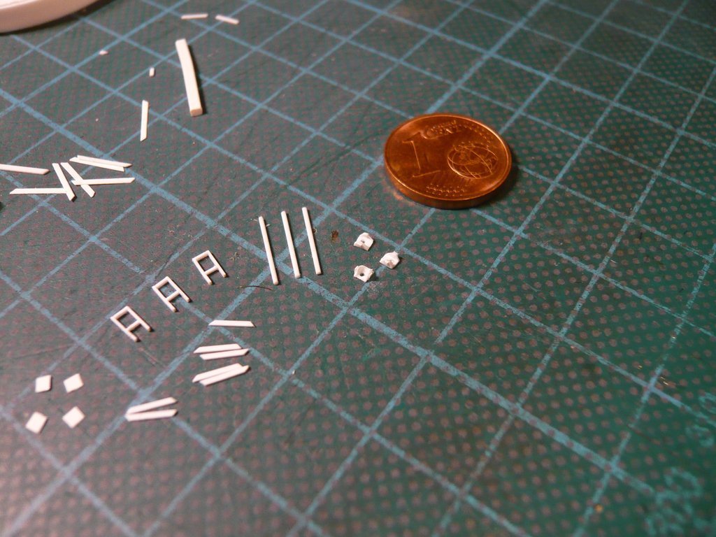 and I can glue in the protective tubes and then move on to the Worm gears and Folding bellows.
__________________
Greetings from Germany Manfred Under construction: Launch Pad 39A with Challenger STS-6 (1:144)
|
|
#2758
02-02-2023, 01:04 PM
|
||||
|
||||
|
Hello everybody,
and thus to the Folding bellows, their assembly sequence I've quickly recapitulated in my former Reply #2751. First, I glued the Lifting spindle protective tubes into the holes in the Double-angle holders. In order not to break off the already glued tiny Angle holders on the sides, this time I clamped the holders at the front and back between the rulers, 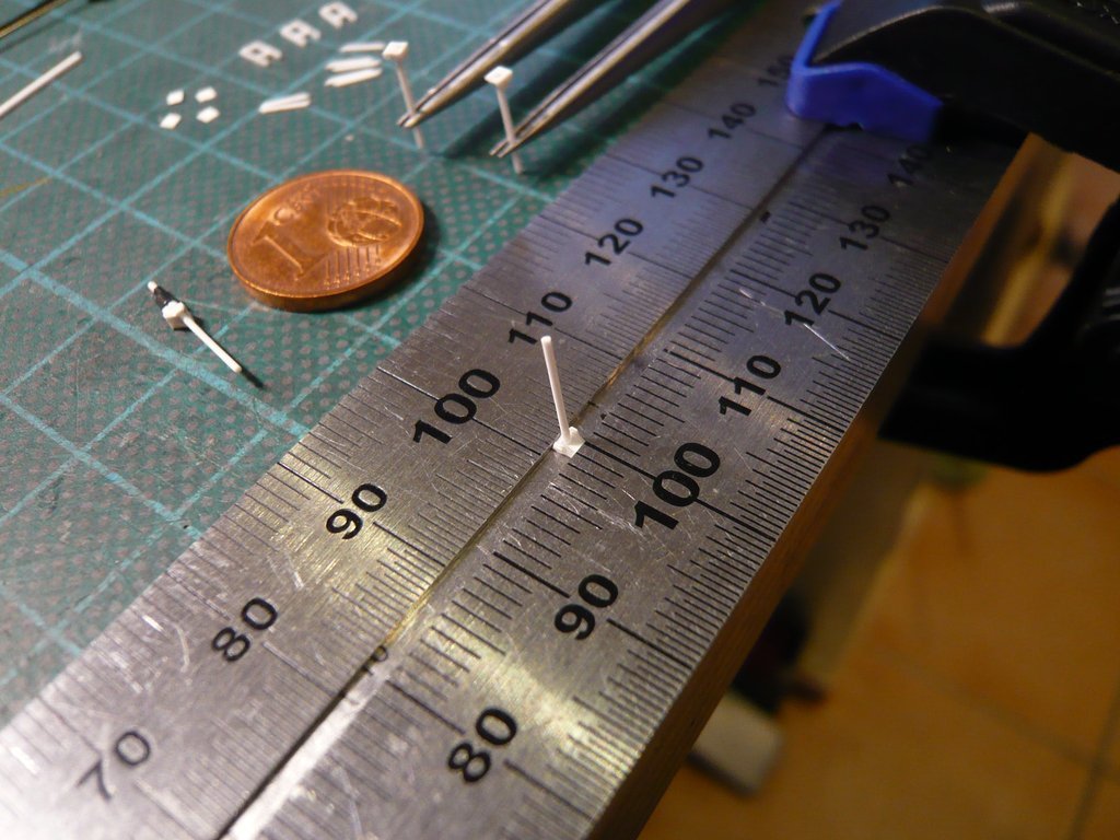 as well as aligned their seat in scissor tweezers and let dry. 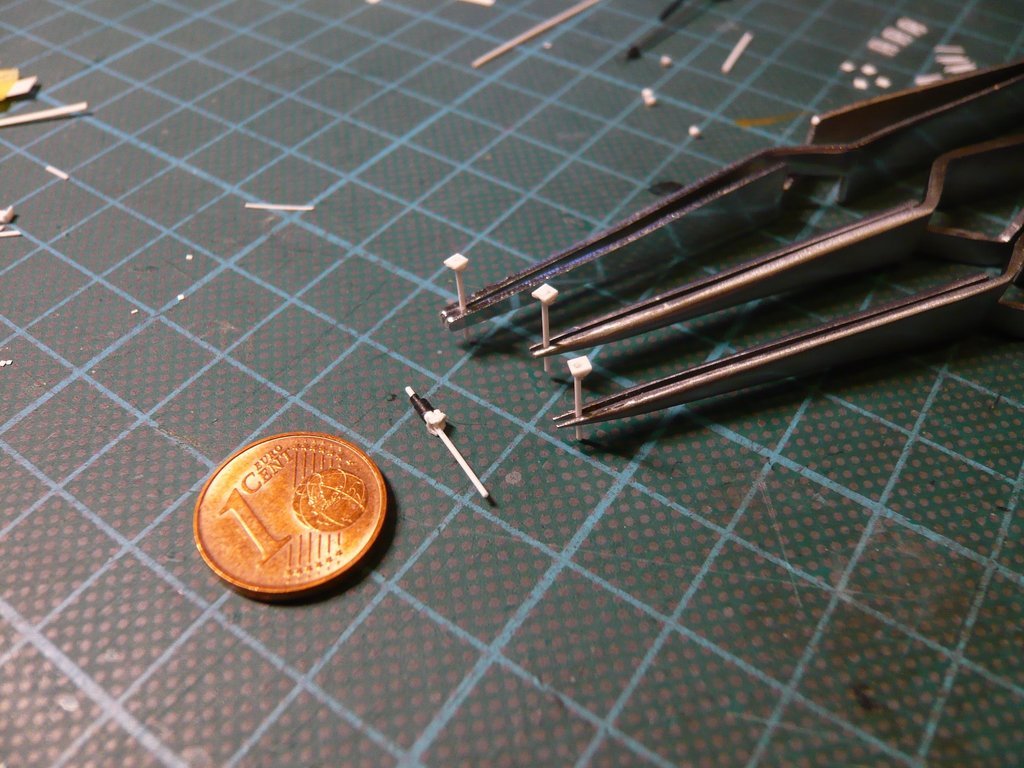 This was followed by the well-known tricky threading of the black rubber sleeves of the bellows onto the sharpened spindle rod (Ø 0,5 mm). After the tricky insertion of the tip into the 1,0 mm long thinner upper sleeve (Ø 0,6 mm), it was pushed up to 1,5 mm in front of the rod end. 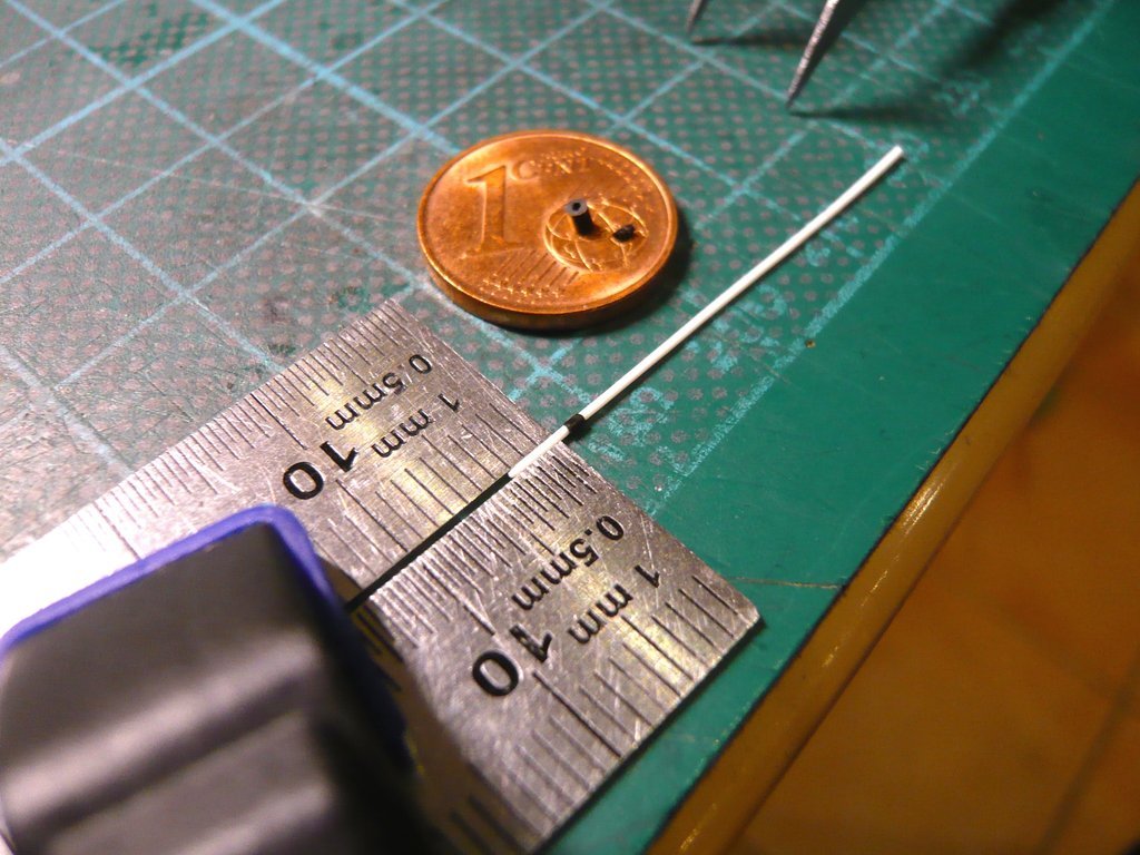 Then the 1,5 mm long lower sleeve (Ø 1,4 mm) was pushed on, which was much easier. 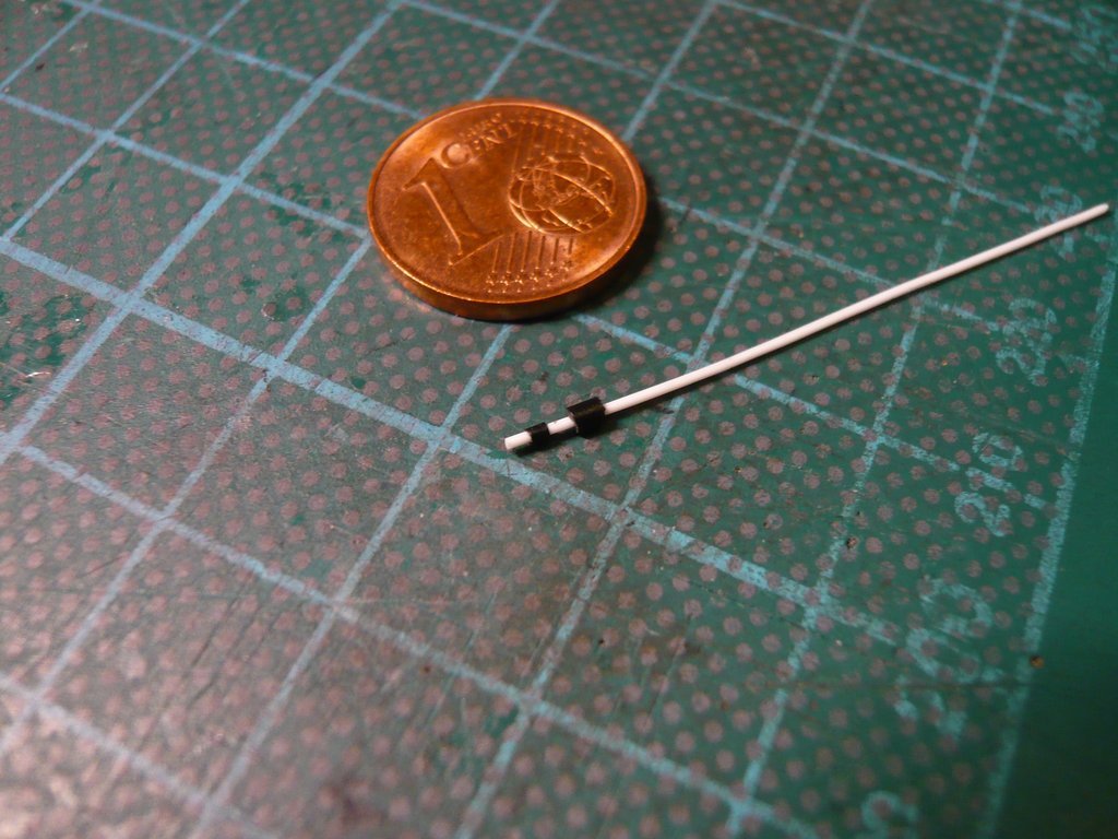 After gluing, the round rod was cut off flush, with which the 2nd Folding bellows was finished. 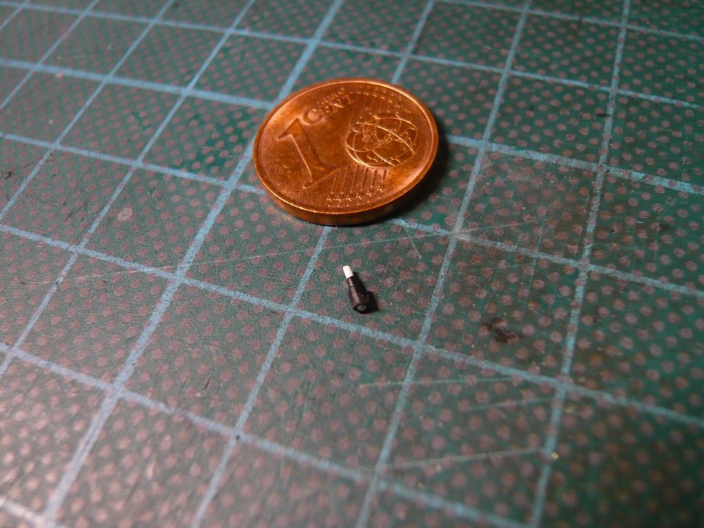 In the same way the two remaining bellows followed. Once you know how it's done, it's only half as bad. 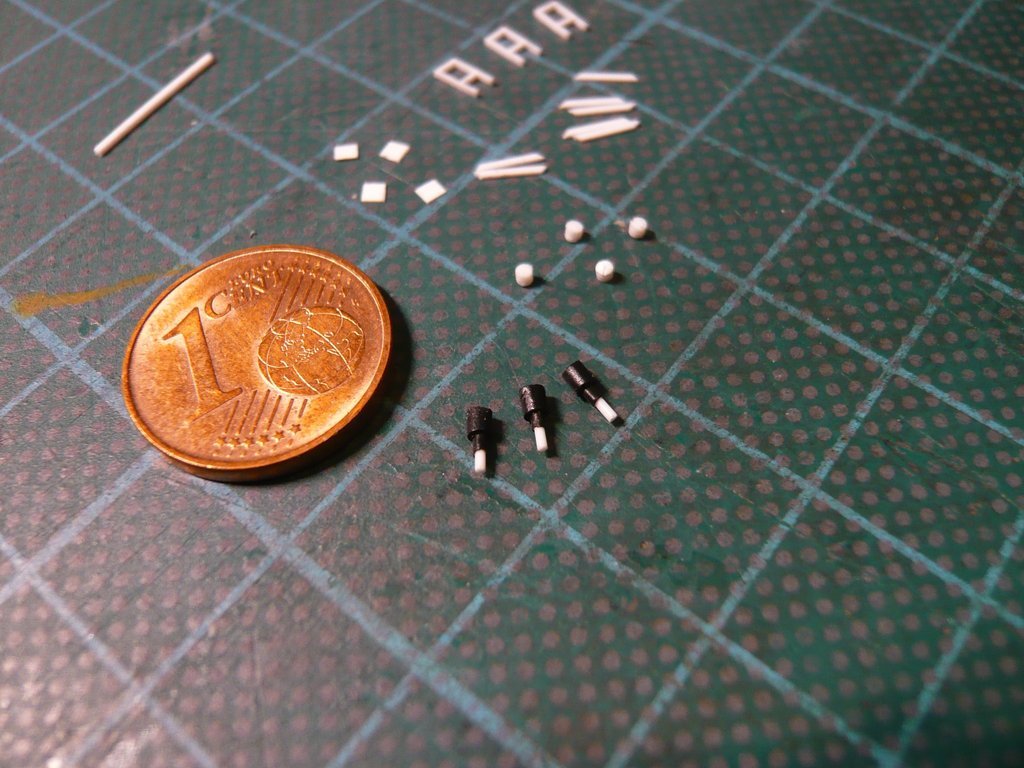 Then I've still scratched the three Worm gears in the known way. 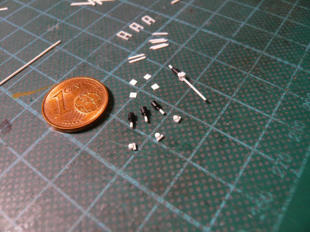 As next step the assembly of the Screw jacks can follow now, 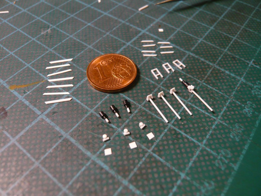 and following this the gluing of the missing frame struts.
__________________
Greetings from Germany Manfred Under construction: Launch Pad 39A with Challenger STS-6 (1:144)
|
|
#2759
02-03-2023, 10:24 AM
|
||||
|
||||
|
Hello everybody,
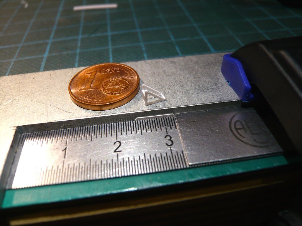
I can be honest, it is a new challenge every day to sit down at my craft table because I know what is waiting there again for me ... A little fun on the side.  In our German forum, a friend was astonished at that my components are narrower than the protruding edge of the 1 Cent coin.  And if he really means the width of the protruding edge of my constant companion, then according to the current measurement it is 0,46 mm wide, which shows, that some of my parts are meanwhile smaller indeed. 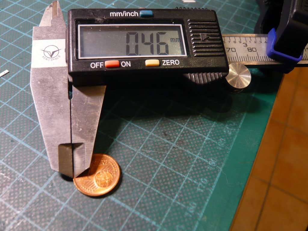 Today I was satisfied with gluing the vertical struts to the frame, 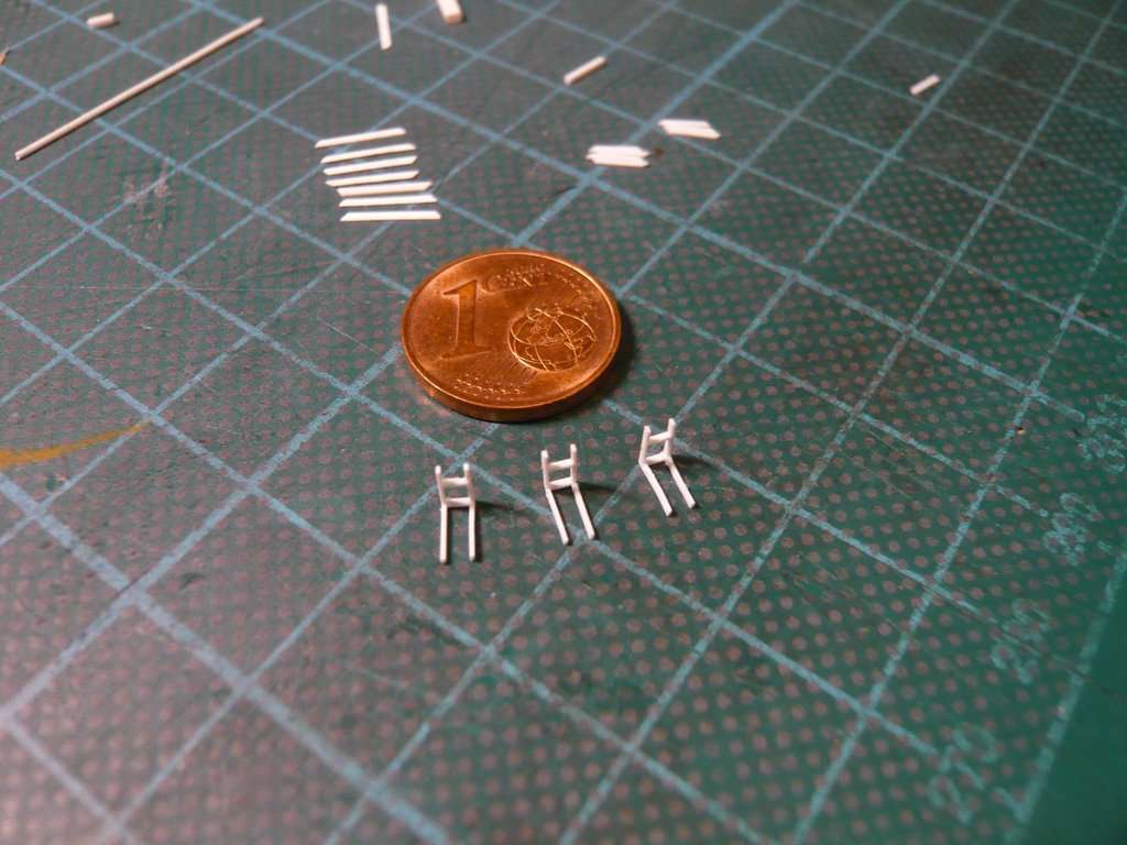 what was also the same stressful business as last time (Reply #2753), 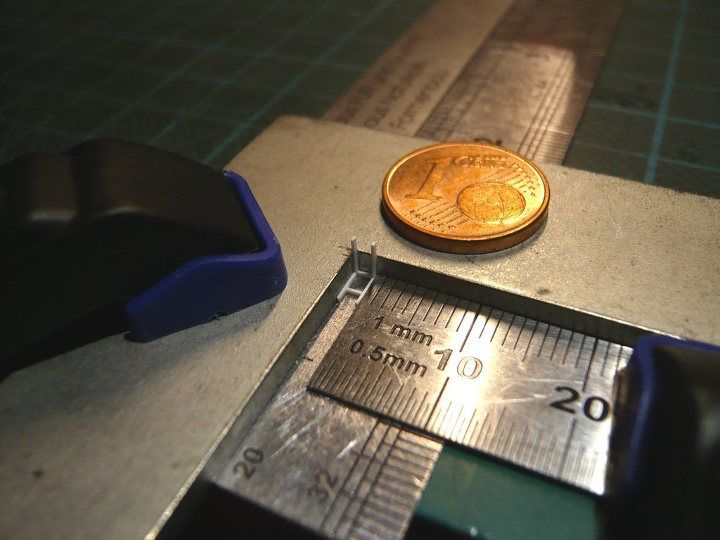 especially since immediately the first strut dropped out of the tweezers when dipping into the glue blob and was therefore scrap.  The squirrel laboriously feeds itself and is hopping from strut to strut... 
__________________
Greetings from Germany Manfred Under construction: Launch Pad 39A with Challenger STS-6 (1:144)
|
|
#2760
02-03-2023, 05:40 PM
|
||||
|
||||
|
Hello everybody,
this was followed by gluing the lower small cross struts (0,25 mm x 0,5 mm x 1,5 mm) at the end of the vertical frame struts. 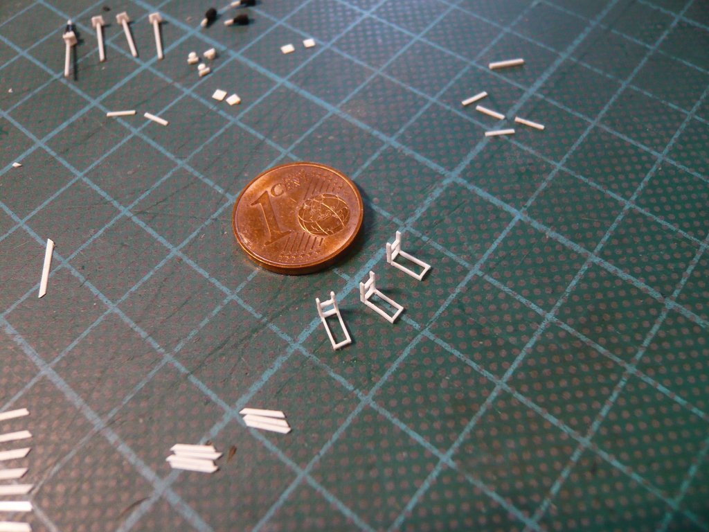 For the gluing of the Diagonal struts I had to scroll back and look at the special arrangement of the steel rulers for fixing.  Due to the modest artificial light conditions, I've set up my improvised Object lighting with a Headband LED, 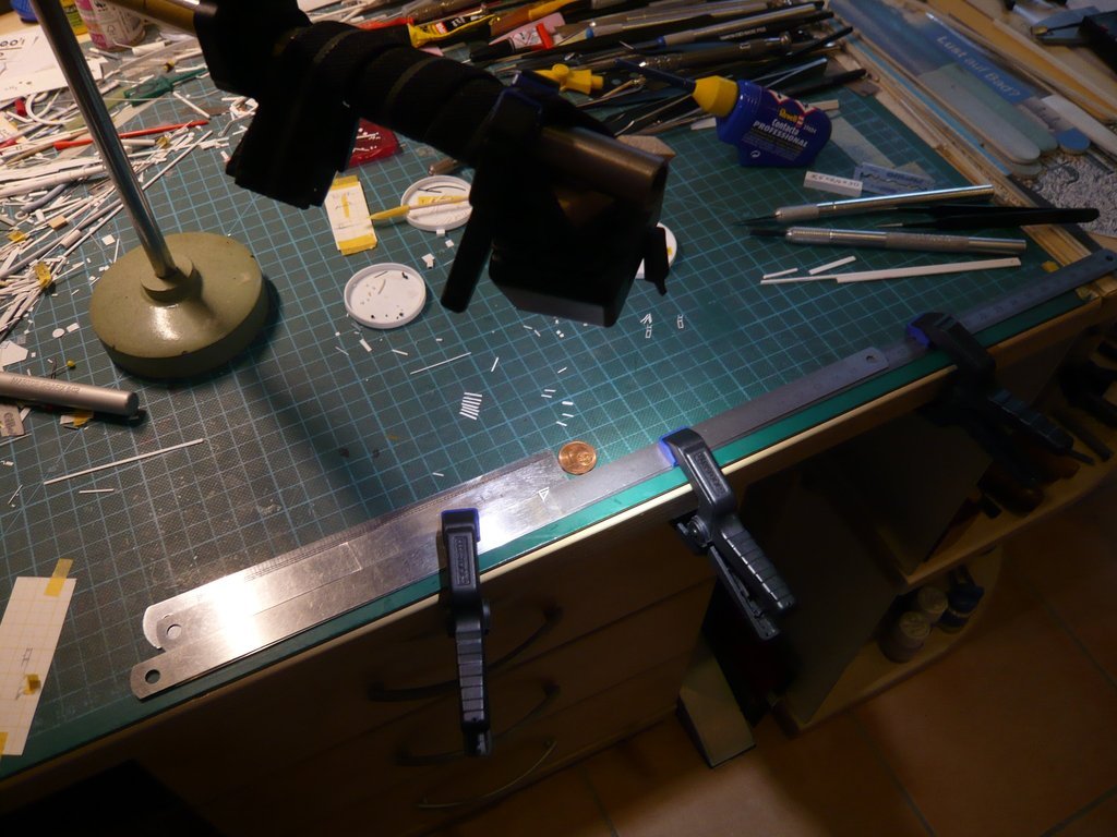 which, together with my Headset magnifying glass, gave me the perfect view.  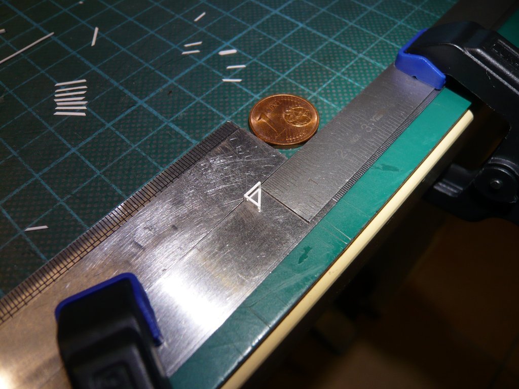 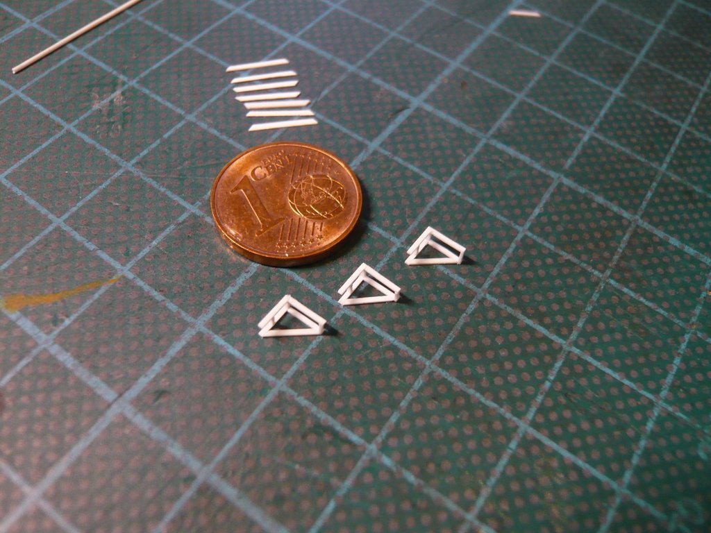 For the gluing of the opposing diagonal struts, the frames had to be fixed non-slip as usual using the super magnets. 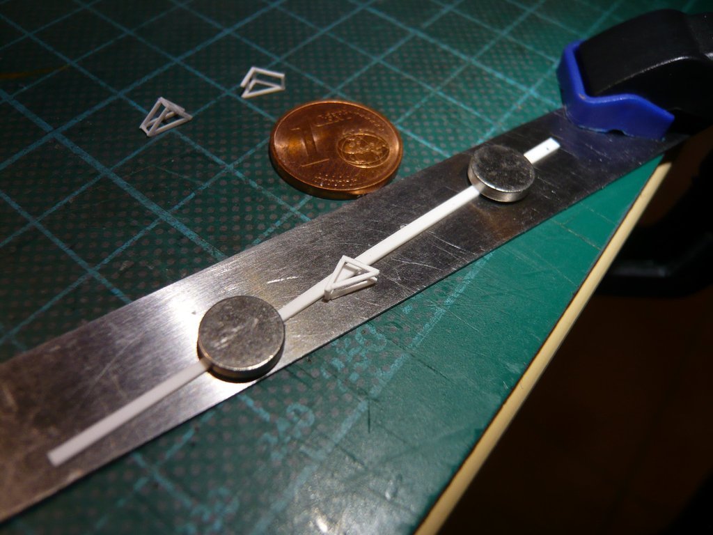 And then the frames were finally done. 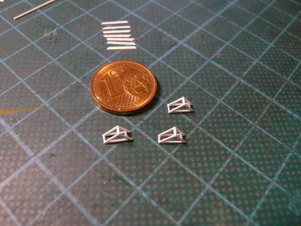 Next, the Worm gears and Folding bellows can be glued to the Double angle holders. Always nice one thing at a time.
__________________
Greetings from Germany Manfred Under construction: Launch Pad 39A with Challenger STS-6 (1:144)
|
 |
|
|


 Linear Mode

