


|
|
|
#2761
 02-03-2023, 07:00 PM
|
|||
|
|||
|
Anyone feel the need to measure things that are still wider than Manfred’s smaller parts? My exact-o blade for instance. Haha
__________________
Happy Crafting - Scot On the Bench: Planck and Hershcel 
|
|
#2762
02-04-2023, 08:09 AM
|
||||
|
||||
|
Well roared, lion, hahaha ...
 
__________________
Greetings from Germany Manfred Under construction: Launch Pad 39A with Challenger STS-6 (1:144)
|
|
#2763
02-07-2023, 05:58 PM
|
||||
|
||||
|
Hello everyone,
today in a quick way some images of the gluing of the three remaining Screw Jacks without many words.  After gluing the Gear units onto the fixed Base plates (0,13 mm x 1,4 mm x 1,5 mm)  the Folding bellows were glued onto the Worm gears one after the other.  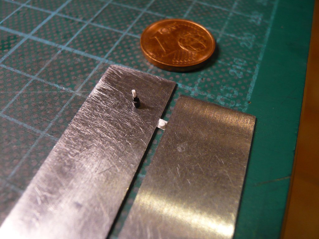 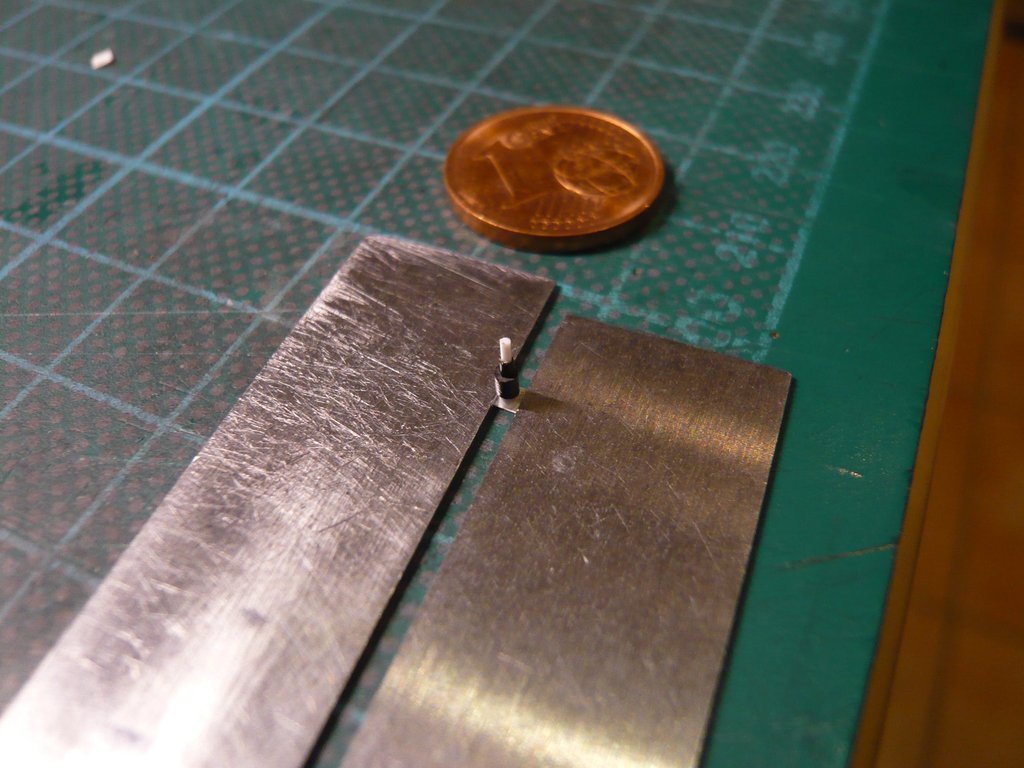 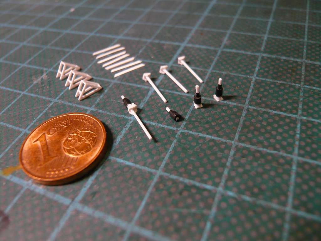 And here they are standing in rank and file like the tin soldiers,  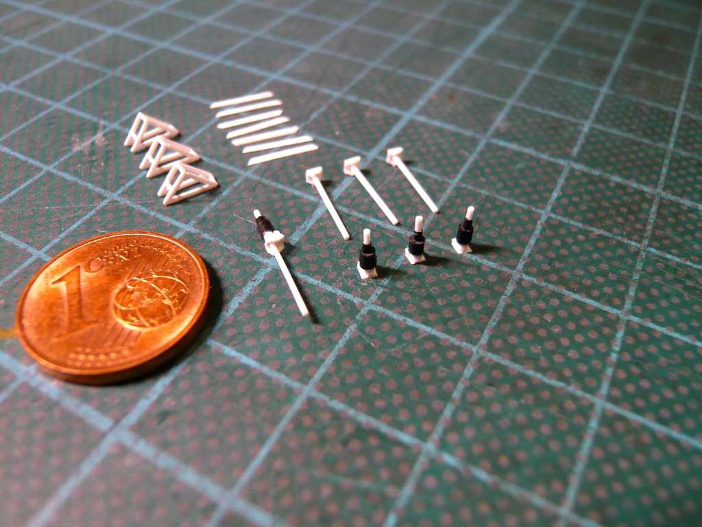 and can next be glued onto the Double angle holders. 
__________________
Greetings from Germany Manfred Under construction: Launch Pad 39A with Challenger STS-6 (1:144)
|
|
#2764
02-08-2023, 02:51 PM
|
||||
|
||||
|
Hello friends,
and thus to the final gluing of the Gear units with the Folding bellows on the Double angle holders. 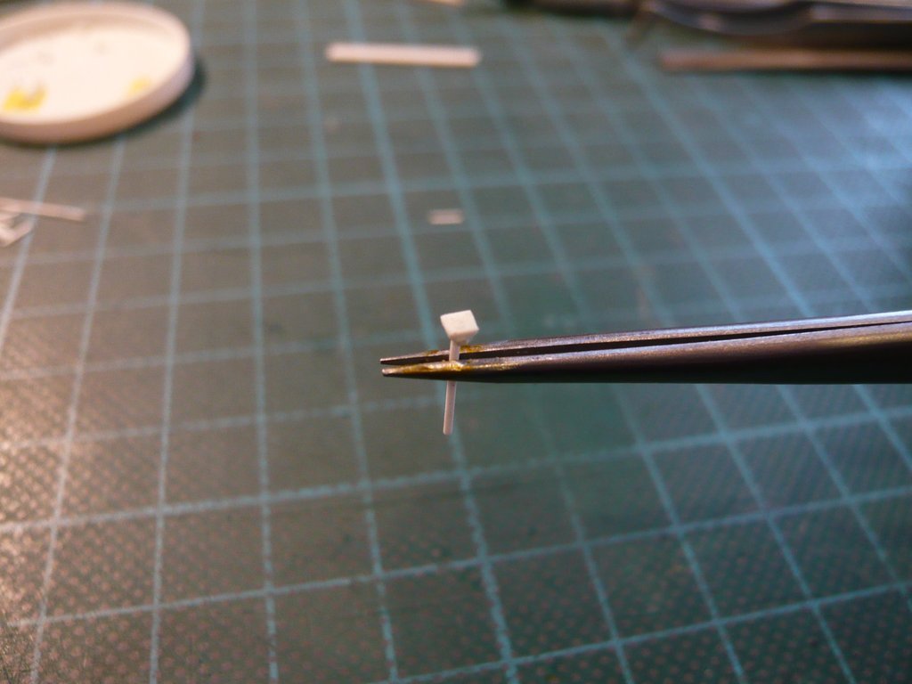 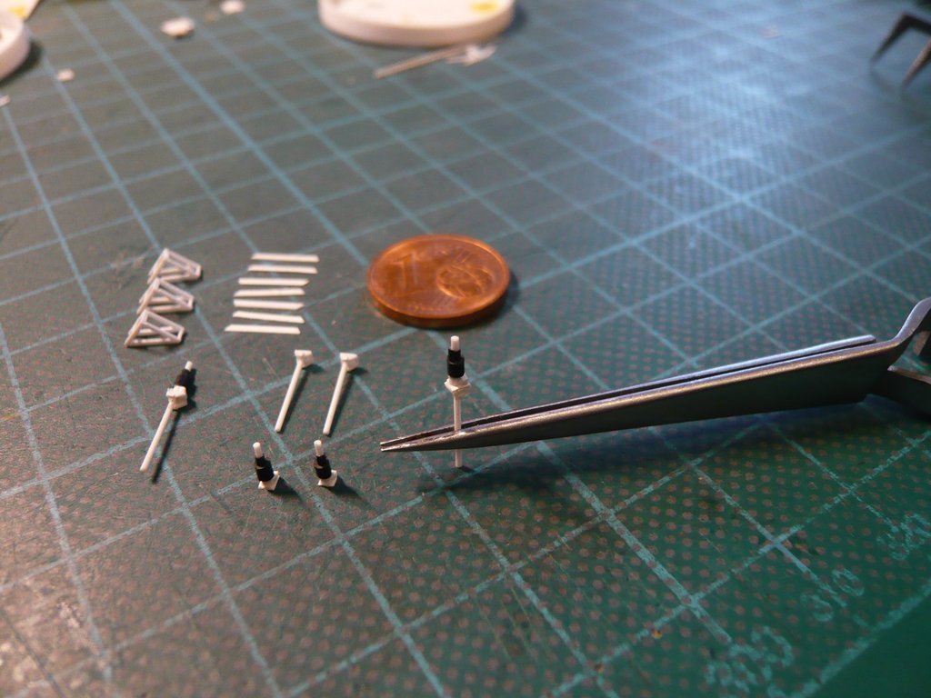 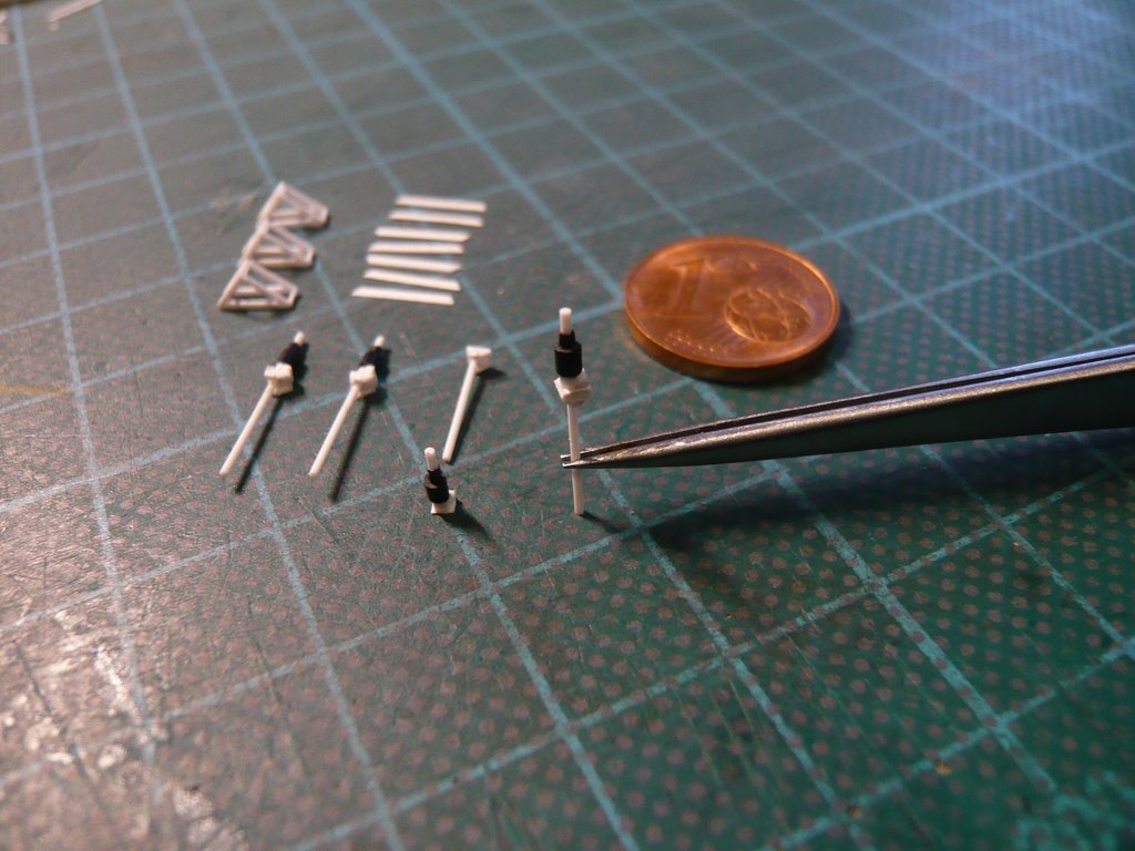 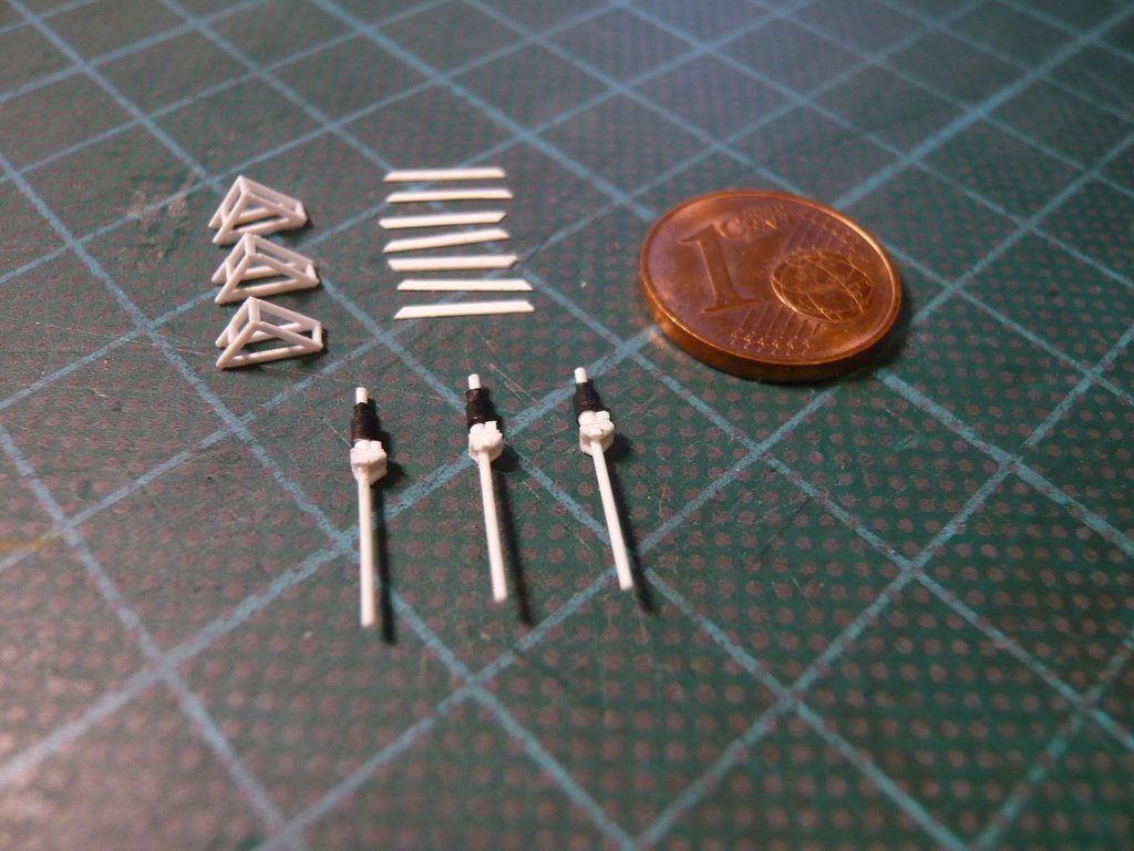 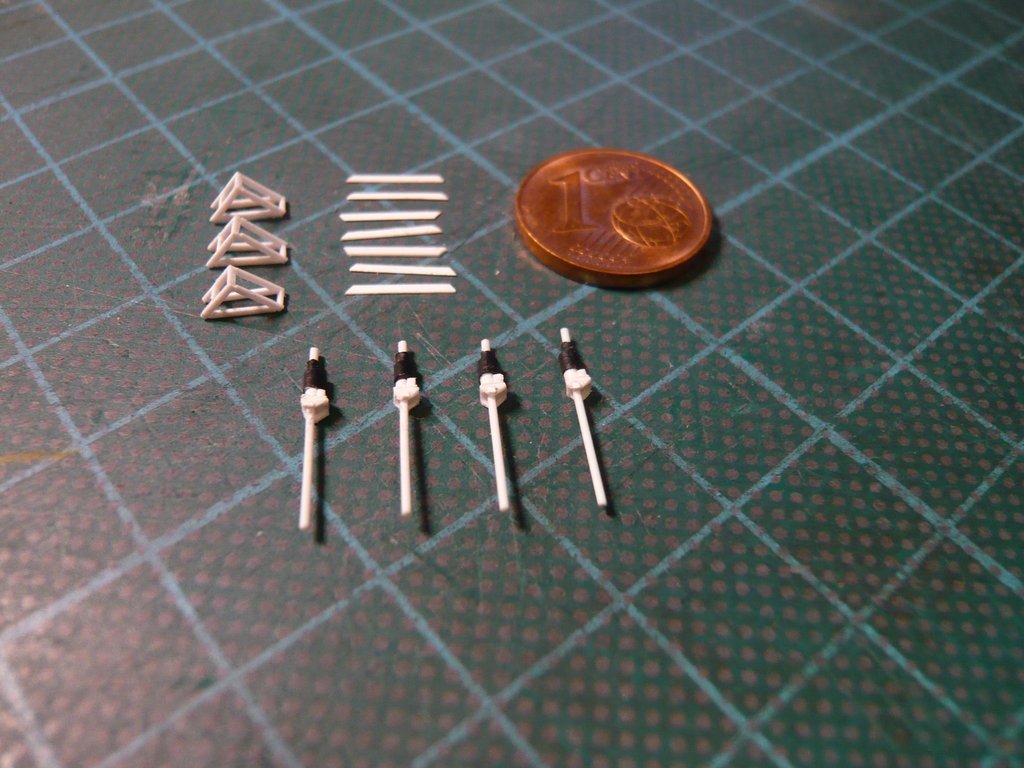 Next the gluing of the vertical braces to the remaining frames will follow, 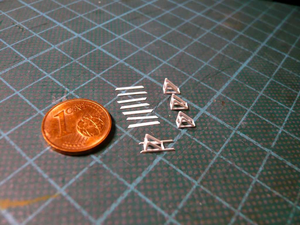 and then the four Screw Jacks are glued to the frames, wherewith finally would be complete this complex subassembly.
__________________
Greetings from Germany Manfred Under construction: Launch Pad 39A with Challenger STS-6 (1:144)
|
|
#2765
02-10-2023, 06:09 PM
|
||||
|
||||
|
Hello everybody,
as advertised, here is the brief overview of gluing the vertical struts to the three remained frames with 1 mm overhang at the top of the frames as I had described for the first frame. 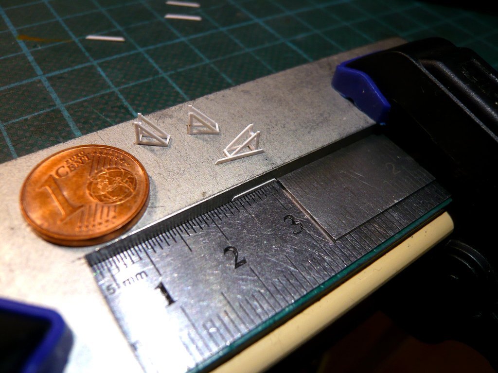 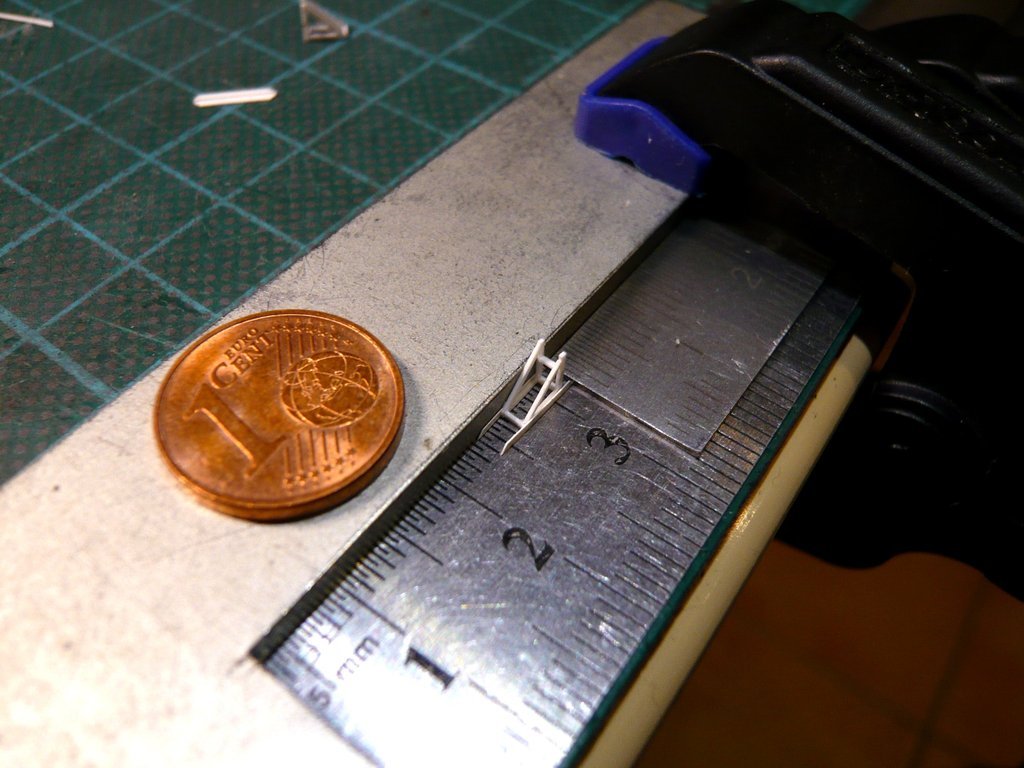 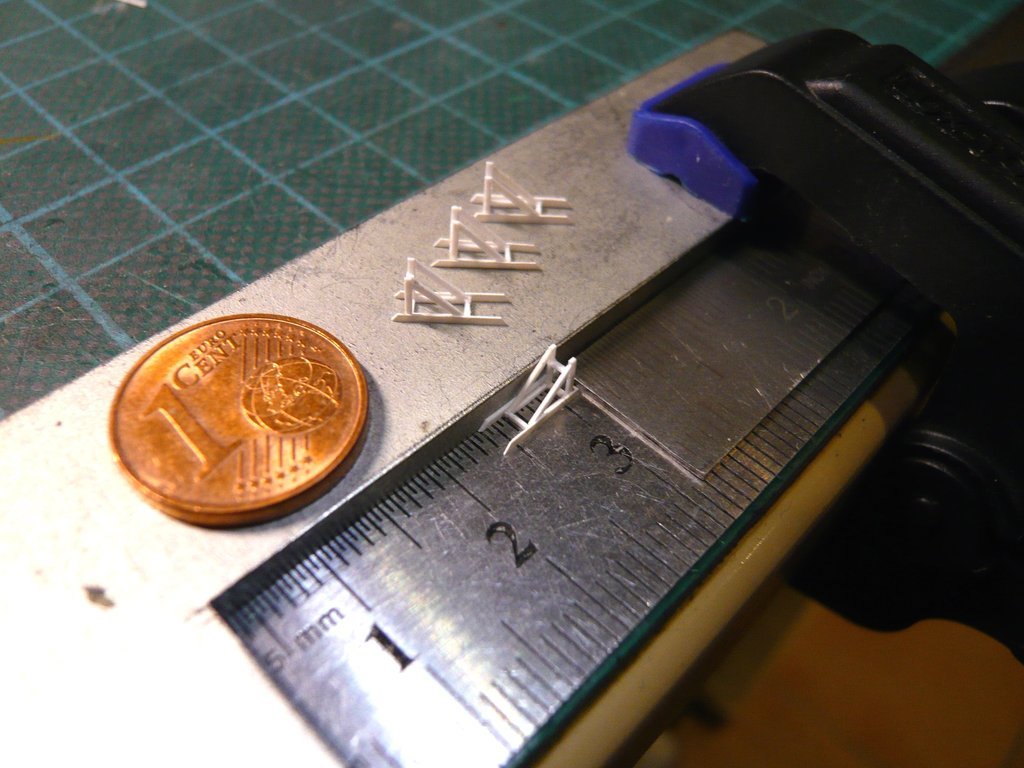 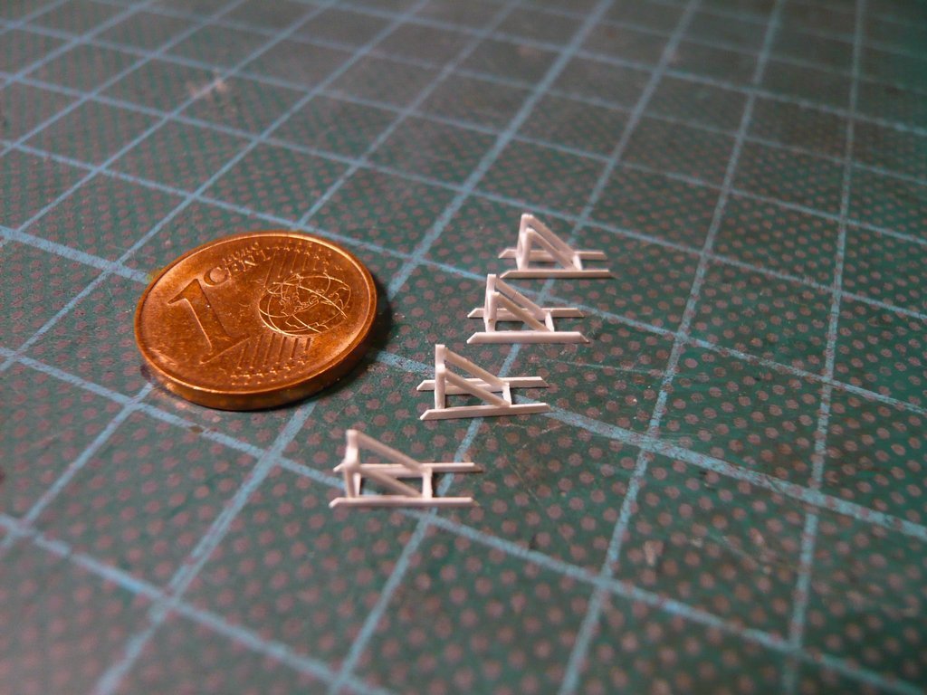 The gluing of the Screw Jacks I'll do tomorrow in daylight.
__________________
Greetings from Germany Manfred Under construction: Launch Pad 39A with Challenger STS-6 (1:144)
|
|
#2766
02-10-2023, 06:11 PM
|
||||
|
||||
|
Hello everybody,
and thus to the trickiest part of the exercise, gluing the Screw Jacks onto the fragile frames, where everything can still go wrong,  but must not go wrong! but must not go wrong! That's why I thought back and forth beforehand as to how the frames could be fixed best and as gently as possible in order to be able to glue the Screw Jacks as centrally and precisely as possible to the front edge.  Finally, I've fixed the frame with narrow tape strips on a steel ruler, the lower struts with 2 mm tape, and the upper short ends with 1 mm tape, which resulted in a sufficiently tight fit. To try it on, I've clamped the ruler in a small vice and carefully laid down a spindle on it, which was quite a balancing act, but has held up.  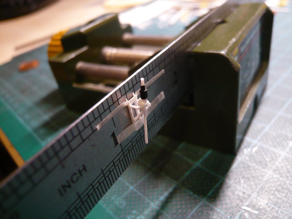 In order to be able to handle better when gluing the parts, I first held the ruler in my hand and dabbed the front ends of the struts lightly with Revell adhesive and put the ruler down for a moment. Then I grabbed the protective tube with the flat tweezers, picked up the ruler with the other hand and carefully placed the spindle with the tiny Angle holders on the adhesive points of the struts, which worked well, so that I could breathe a sigh of relief.  Then I inspected the vertical seat of the spindle from all sides and corrected it slightly, 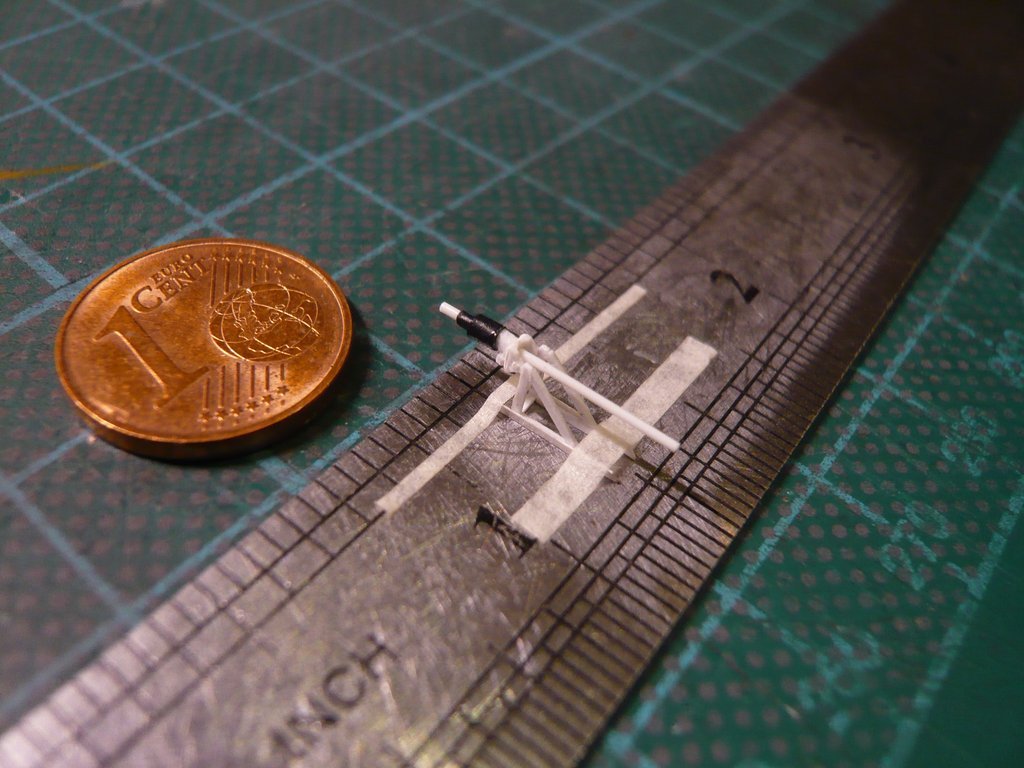 and let all dry for a while.  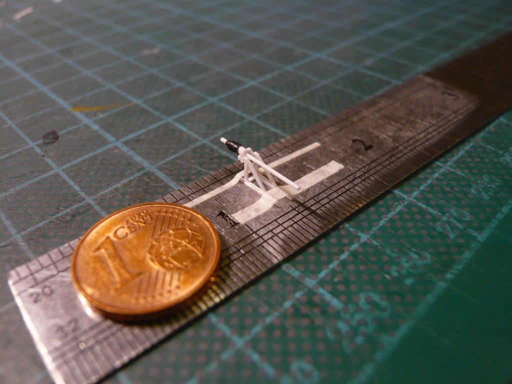 After I carefully removed the tape strips, I was glad that everything worked out and that my plan had worked again perfectly.  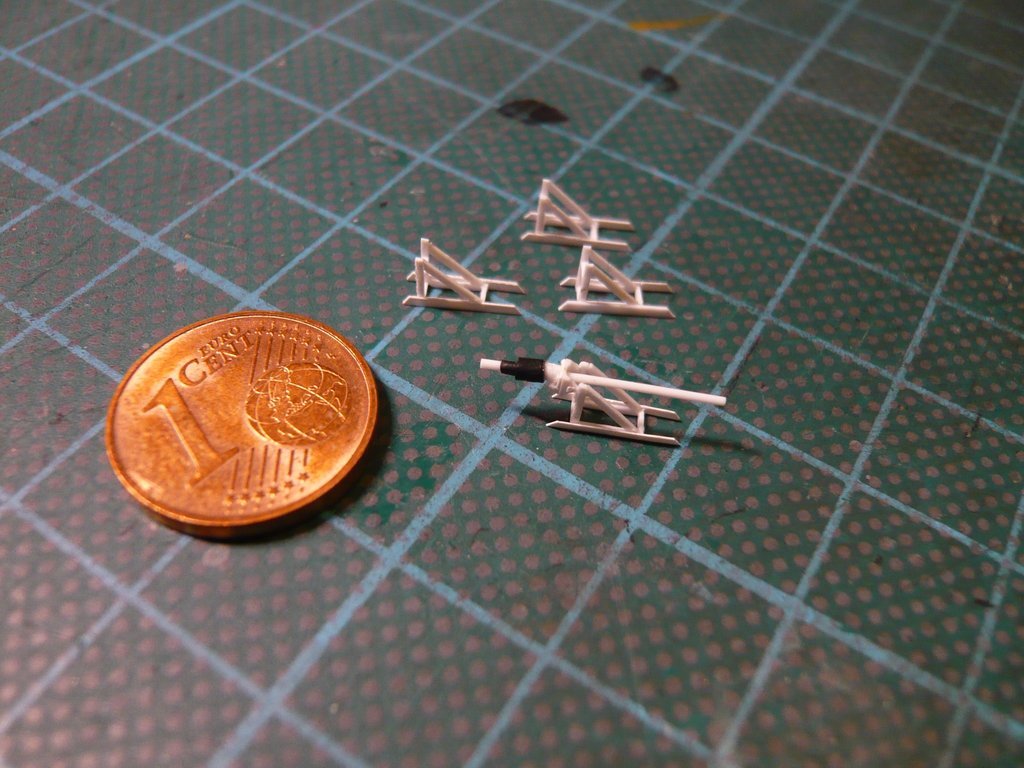 Gluing the remaining three Screw Jacks will become a bit easier already, I hope so.
__________________
Greetings from Germany Manfred Under construction: Launch Pad 39A with Challenger STS-6 (1:144)
|
|
#2767
02-13-2023, 05:01 PM
|
||||
|
||||
|
Hello everybody,
and with that go right to the next Screw Jack, which was indeed easier to do, since the method of gluing has now proven itself. 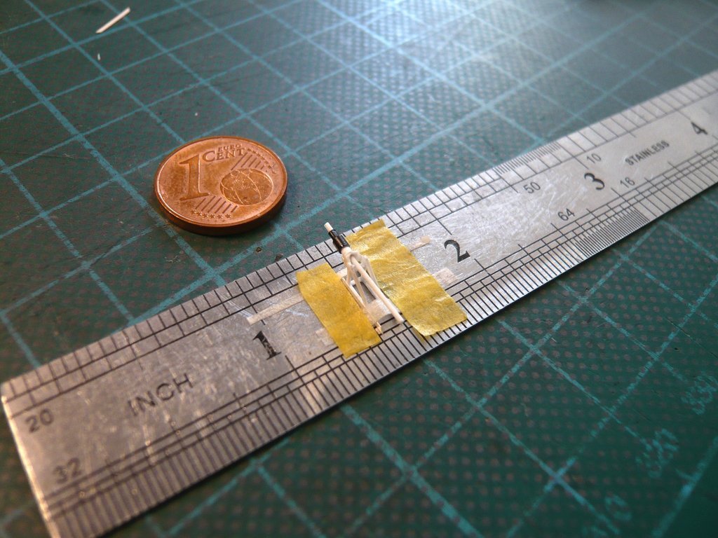 After the tape strips were carefully removed, the seat of the spindle was slightly adjusted, 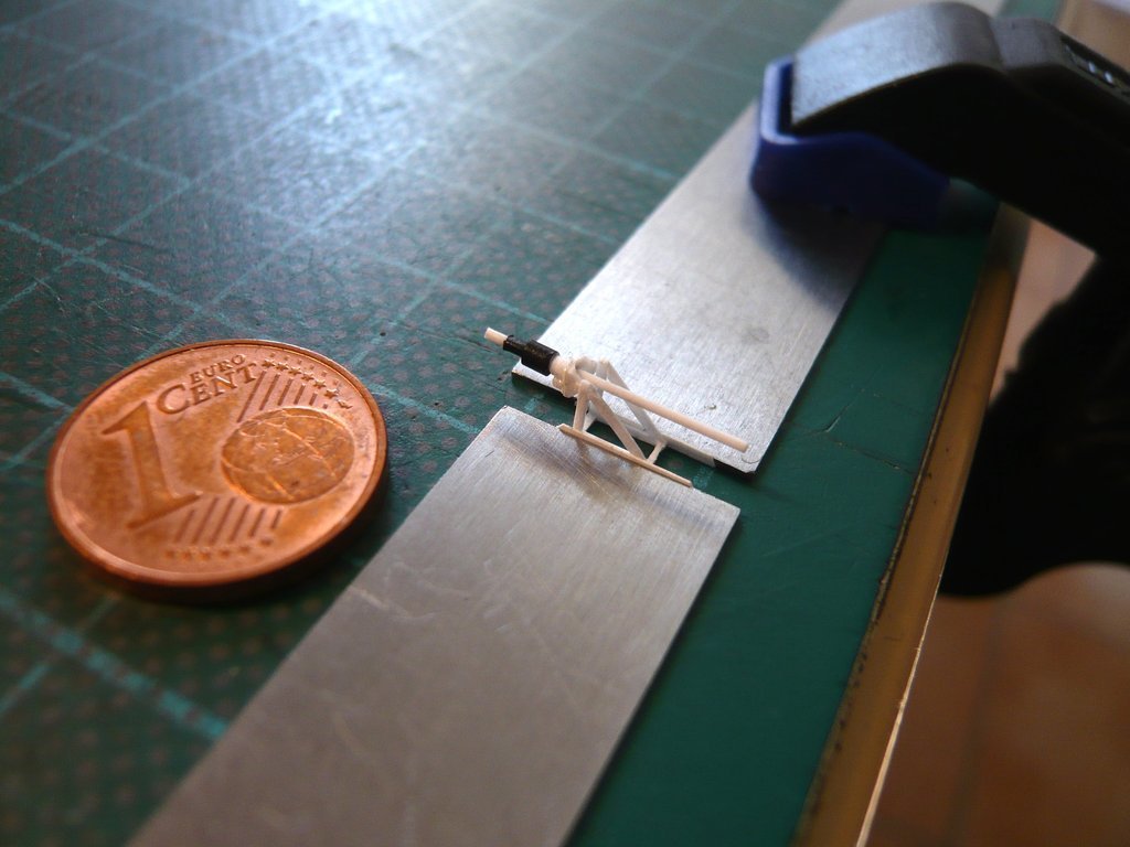 and finally found as perfect,  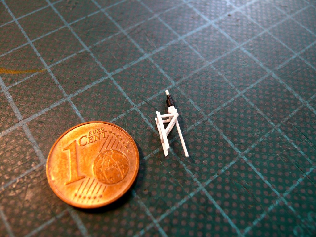 which already half of the Screw Jacks was done. 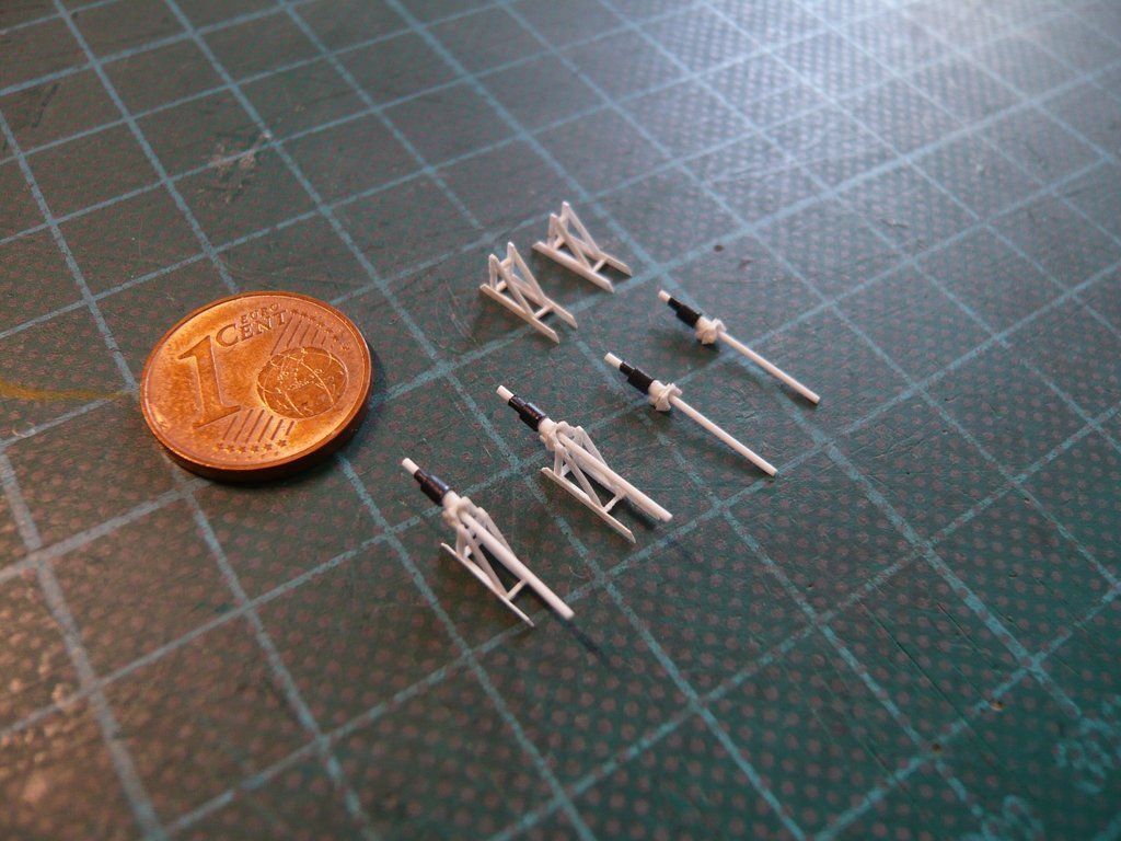 And so it was worth going for a test on the Port Side of the Payload Canister. 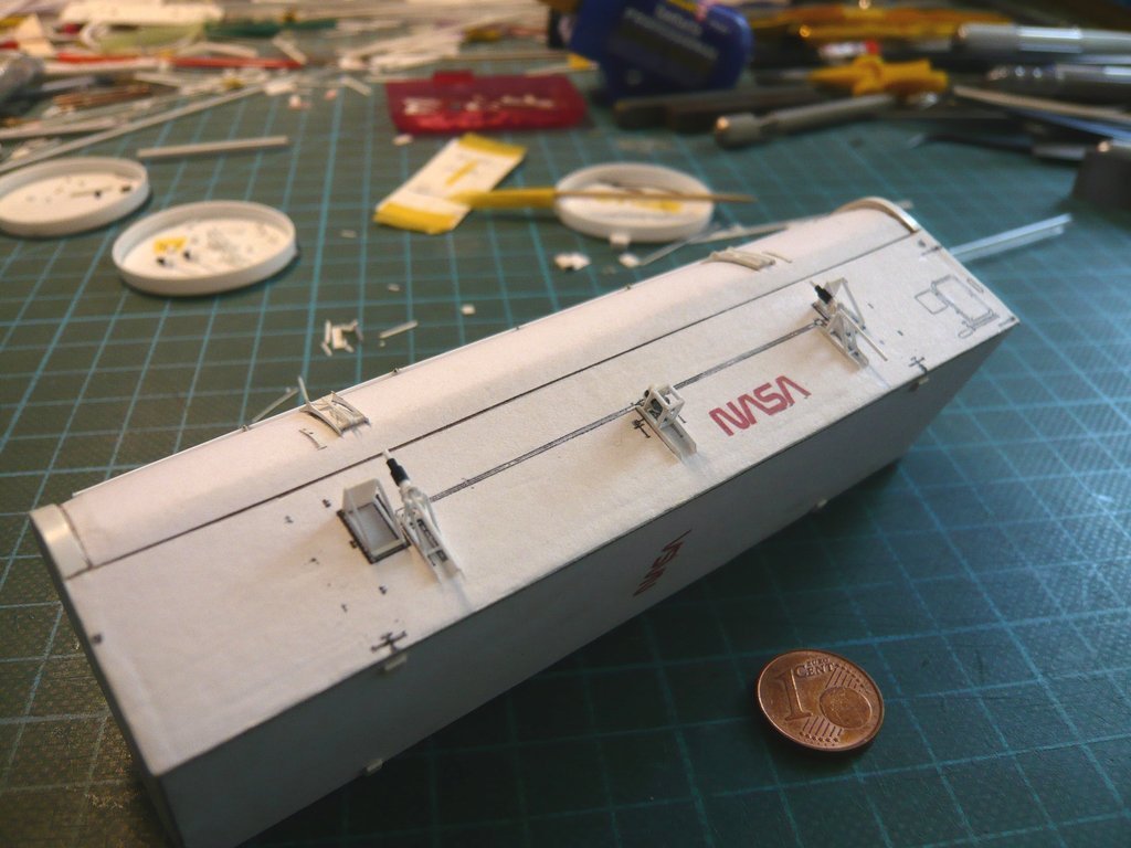 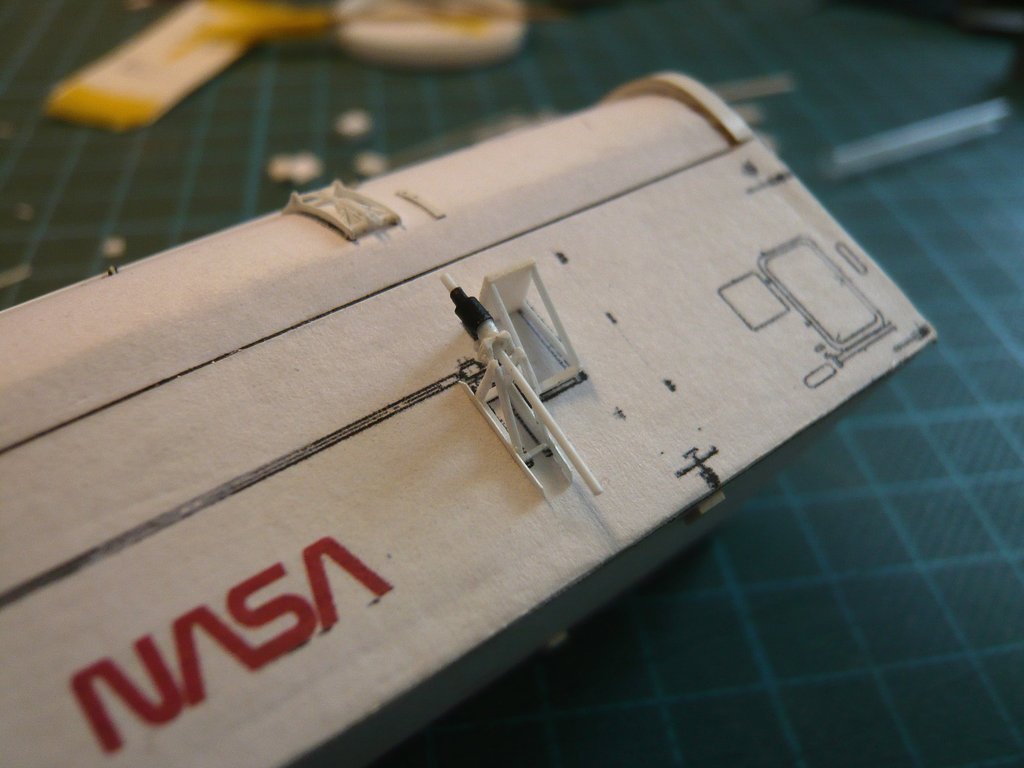 This was followed immediately by the third Screw Jack, 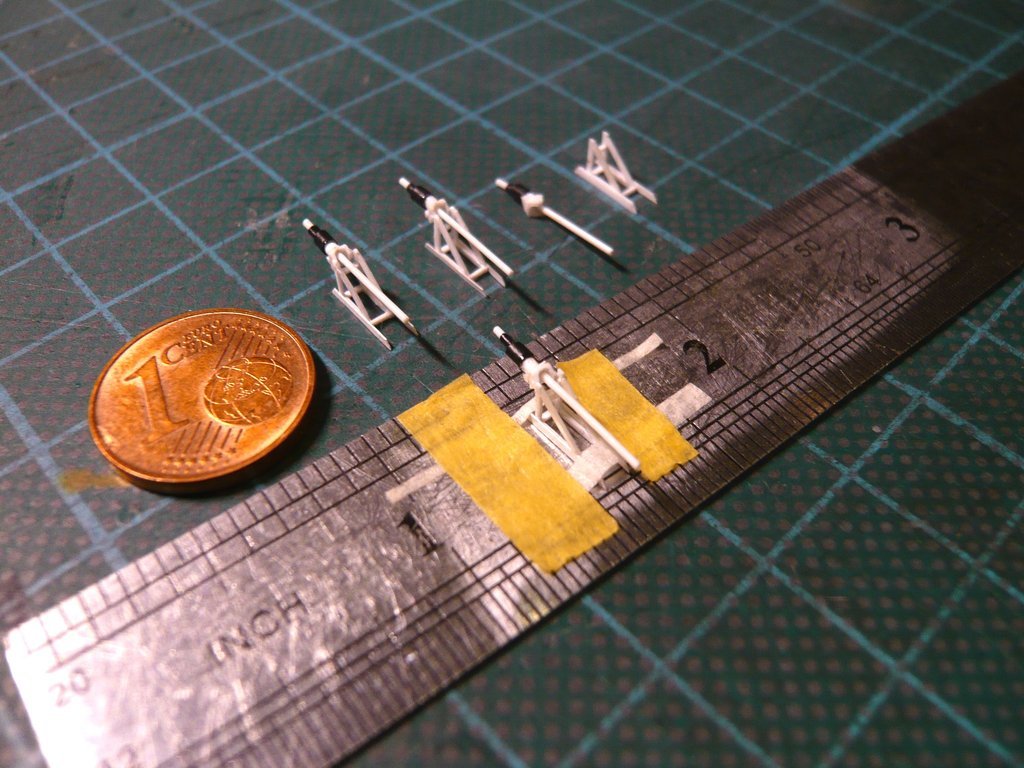 and finally still the fourth one too. 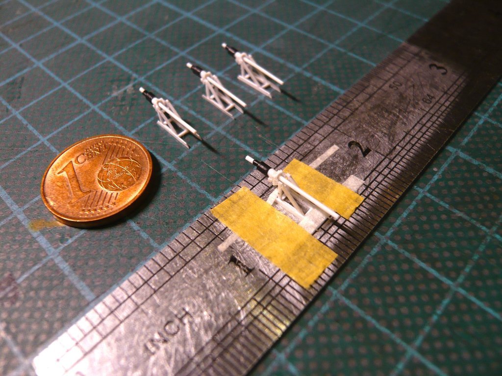 And I think they look pretty much alike, right?  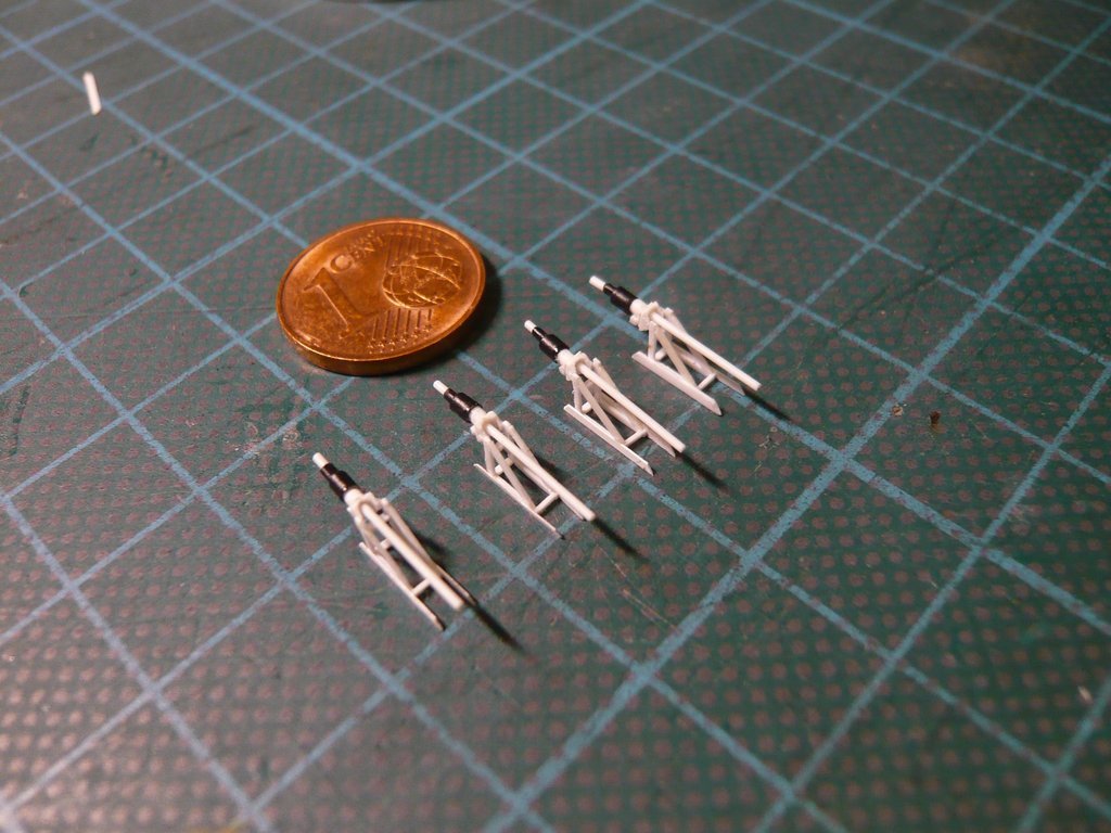 And together with the two Door Actuator Pneumatic Drives, another small but very laborious and tricky milestone has been reached,  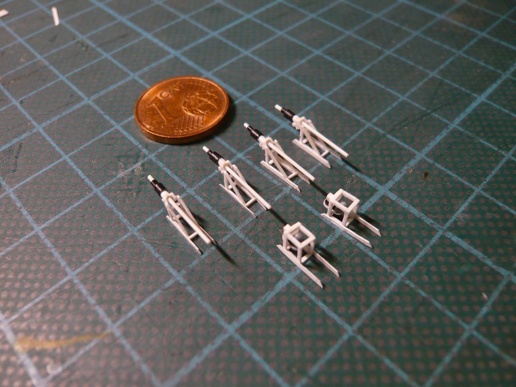 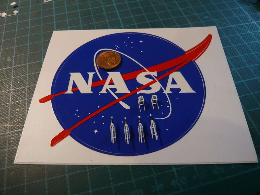 what more than only satisfies me.
__________________
Greetings from Germany Manfred Under construction: Launch Pad 39A with Challenger STS-6 (1:144)
|
|
#2768
02-16-2023, 12:59 PM
|
||||
|
||||
|
Hello everybody,
but in addition to the Screw Jacks and Door Actuator Drives there are a few more details on the side walls that should not be missing. And those are the Ladders right next to the Access Platforms and these Outriggers (folded) at the front end of the canister.  Source: NASA (STS-135) The outriggers can be folded or folded out as needed for the transfer of the canister to the Payload Changeout Room (PCR) of the RSS. In the extended position, the rotatably mounted PCR Guide Shoes slide in vertical guides on both sides of the RSS Payload Bay when the canister is hoisted and thus to keep the shuttle's payload as stable as possible.  Source: NASA (STS-129) Here the guide shoes dip into the guide rails.  Source: NASA (STS-129) On this image I determined the dimensions of the ladders.  Source: NASA (STS-132) For these ladders, I got already these PE Ladders from ABER (1:200-05) a long time ago, 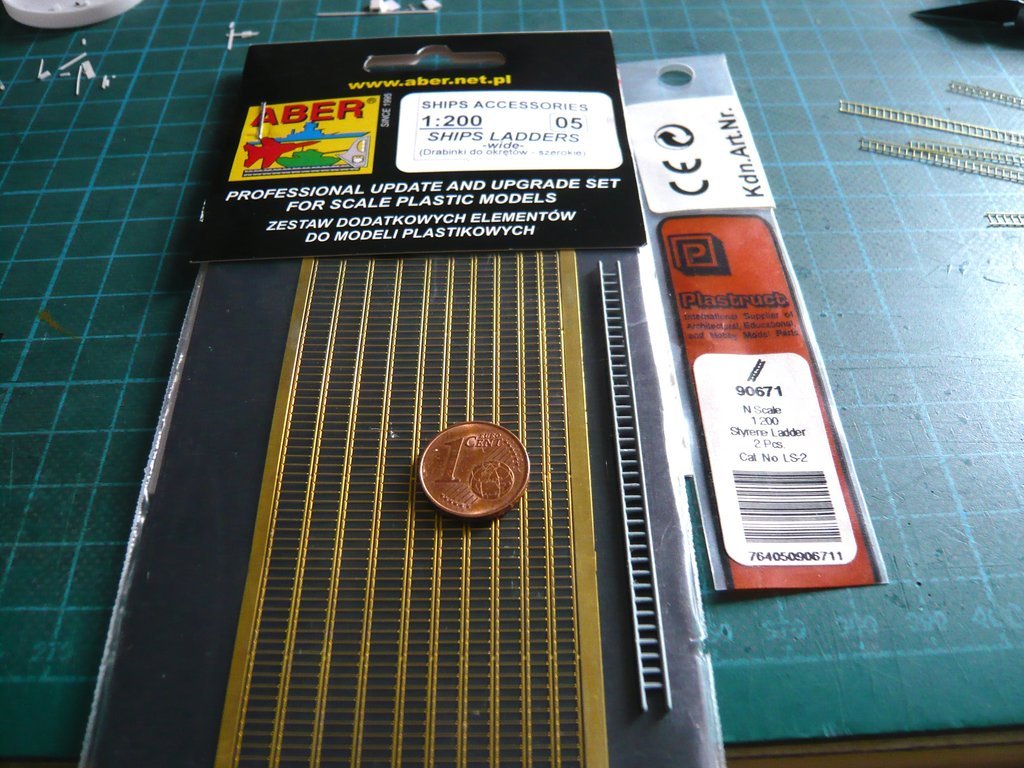 which are offered there as Ships Ladders (wide) in three different widths, of which the middle width (3,5 mm) is well suited for my scale (1:160). The Plastruct Styrene Ladders would have the required width, but they are 'rough wrought-iron work' that one can safely forget.  After cutting out from the PE circuit board, the narrow side bars still have to be bent by 90°, 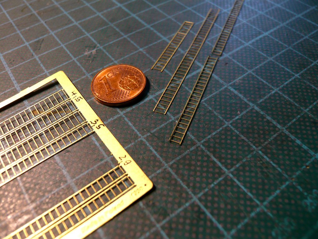 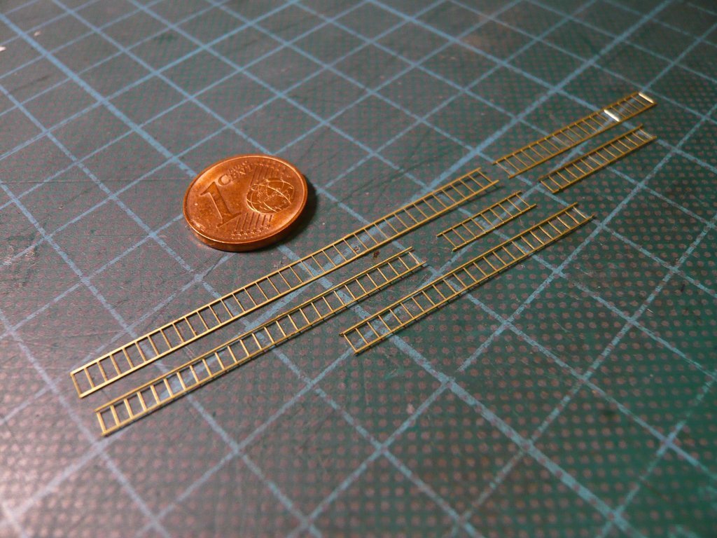 for which a special Hold and Fold tool is needed. 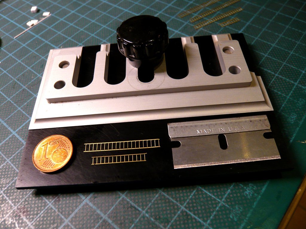  And this ladder size fits well into the mould, 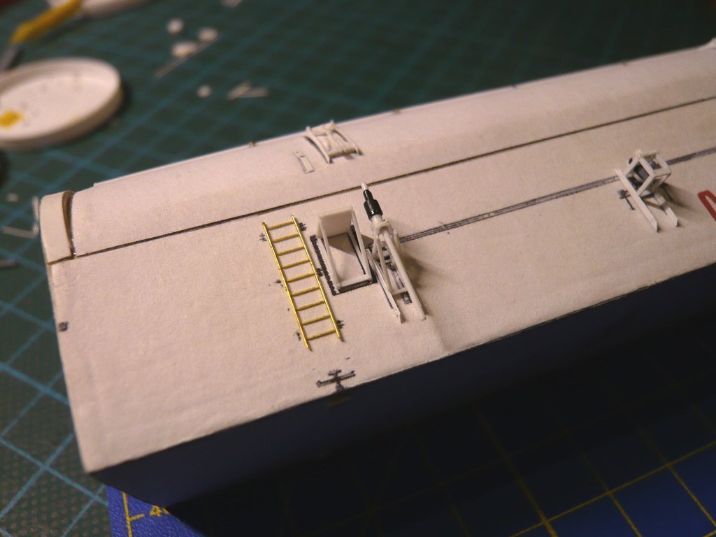 which I can also use for the ladders on the Forward Bulkhead of the canister. Source: forum.nasaspaceflight.com (STS-9, Ares67) And as one can see, there are still also some Railings there that can be folded or folded out as well.
__________________
Greetings from Germany Manfred Under construction: Launch Pad 39A with Challenger STS-6 (1:144)
|
|
#2769
02-20-2023, 03:13 AM
|
||||
|
||||
|
Hello everybody,
but I want to start with the Outriggers, which, similar to the Door Actuators on the canister doors, consist of foldable linkages, at the end of them the PCR Guide Shoes are mounted, which can be seen in the folded state in these two images. Then I've also marked the two Lifting Trunnions for hoisting the canister, which are also still to do.  Source: NASA (STS-135) For hoisting the canister into the RSS Payload bay , the outrigger is folded out by locking the lower Support strut into the upper bracket marked here, 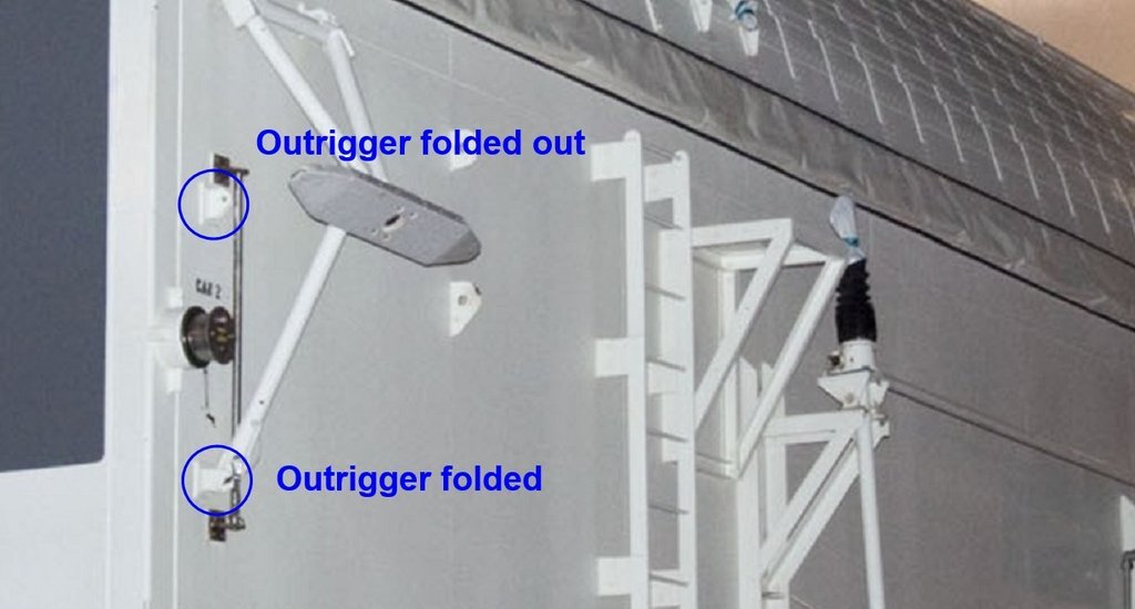 Source: NASA (STS-135) which can also be seen in these drawings. 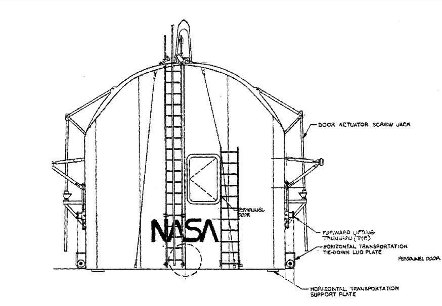 Source: Library of Congress, HAER FL-8-11-I 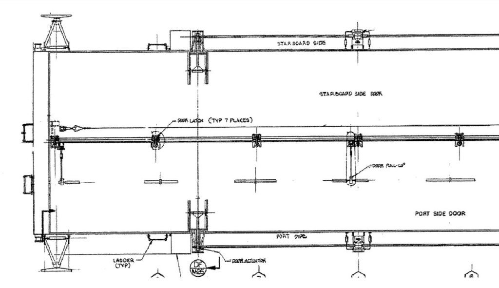 Source: Library of Congress, HAER FL-8-11-I But before assembling the linkages, I've looked for NASA photos, on which one can see the structure of the outrigger better, and actually have made a find at STS-135, which is extensively photo-documented as the last Shuttle mission.  Source: NASA (STS-135) On it one can see the structure of the triangular support frame, which is rotatably mounted at the base in brackets on the side wall and connected to the guide shoe at the other end. The swiveling support strut is rotatably mounted on the shoe's holder, which can be locked in the folded state or, as shown here, in the unfolded state, as required.  Source: NASA (STS-135) And to this size the outrigger must now be shrunk. 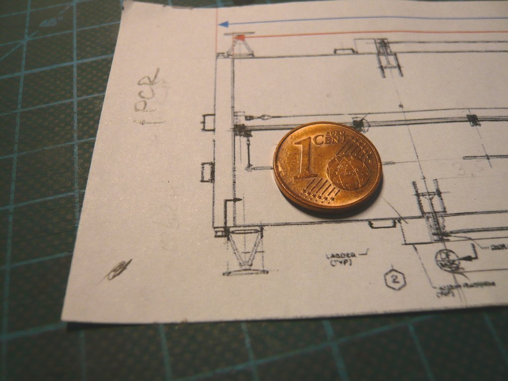 For the PCR Guide Shoe I used an Evergreen Strip (0,5 mm x 1,5 mm), which was sanded down to a width 1,3 mm. 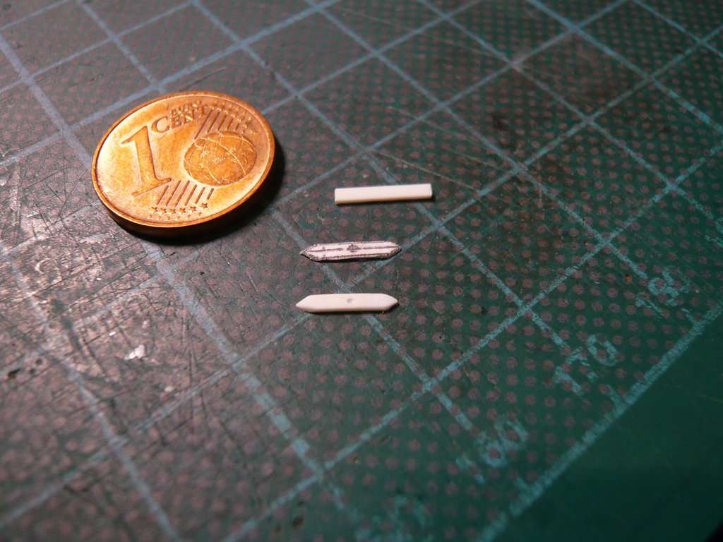 For the struts I will use an Evergreen rod (Ø 0,4 mm), I have provisionally laid out them here. 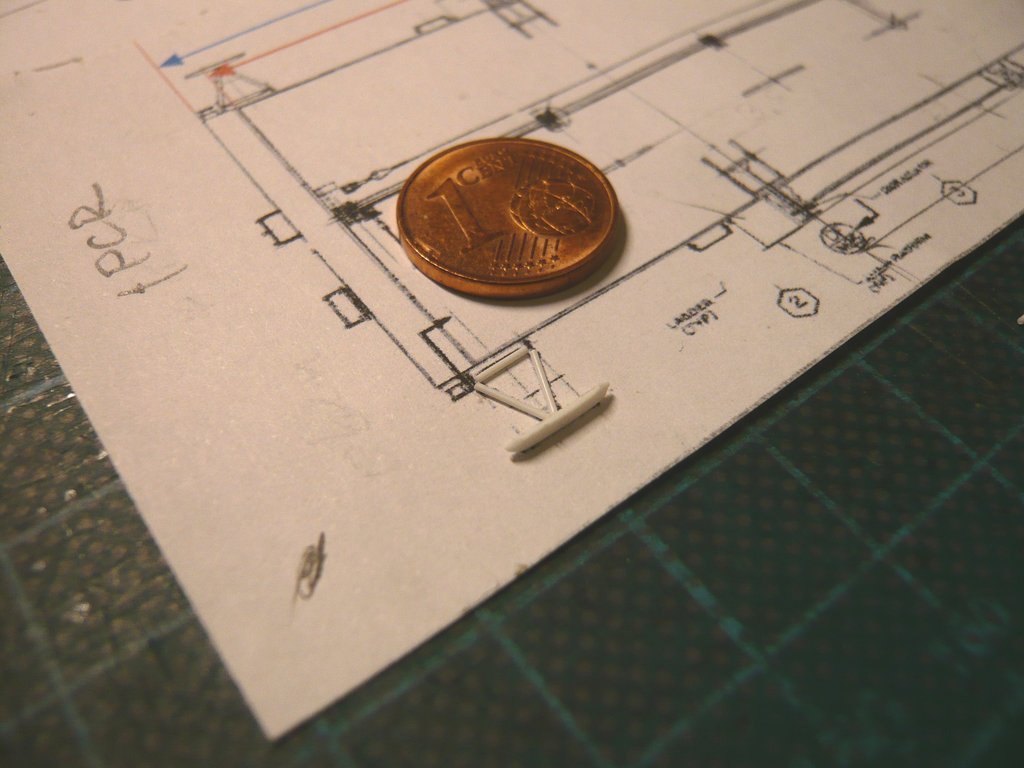 So much for today.
__________________
Greetings from Germany Manfred Under construction: Launch Pad 39A with Challenger STS-6 (1:144)
|
 |
|
|


 Linear Mode

