


|
|
|
#2801
 03-26-2023, 10:45 AM
|
|||
|
|||
|
Manfred,
This is both amazing and crazy! (In a good way!). Your work arounds are genius and it gives me ideas for things I'm stuck on. Thanks for sharing your awesome work. (There is somebody out here...) Dan 
|
|
#2802
03-26-2023, 05:46 PM
|
||||
|
||||
|
Thanks Dan for your overwhelming compliments,
 and for being in here too. and for being in here too.  Stay tuned and keep getting inspired. And if you have any questions just ask, maybe I can help you.  
__________________
Greetings from Germany Manfred Under construction: Launch Pad 39A with Challenger STS-6 (1:144)
|
|
#2803
04-02-2023, 06:38 PM
|
||||
|
||||
|
Hello everybody,
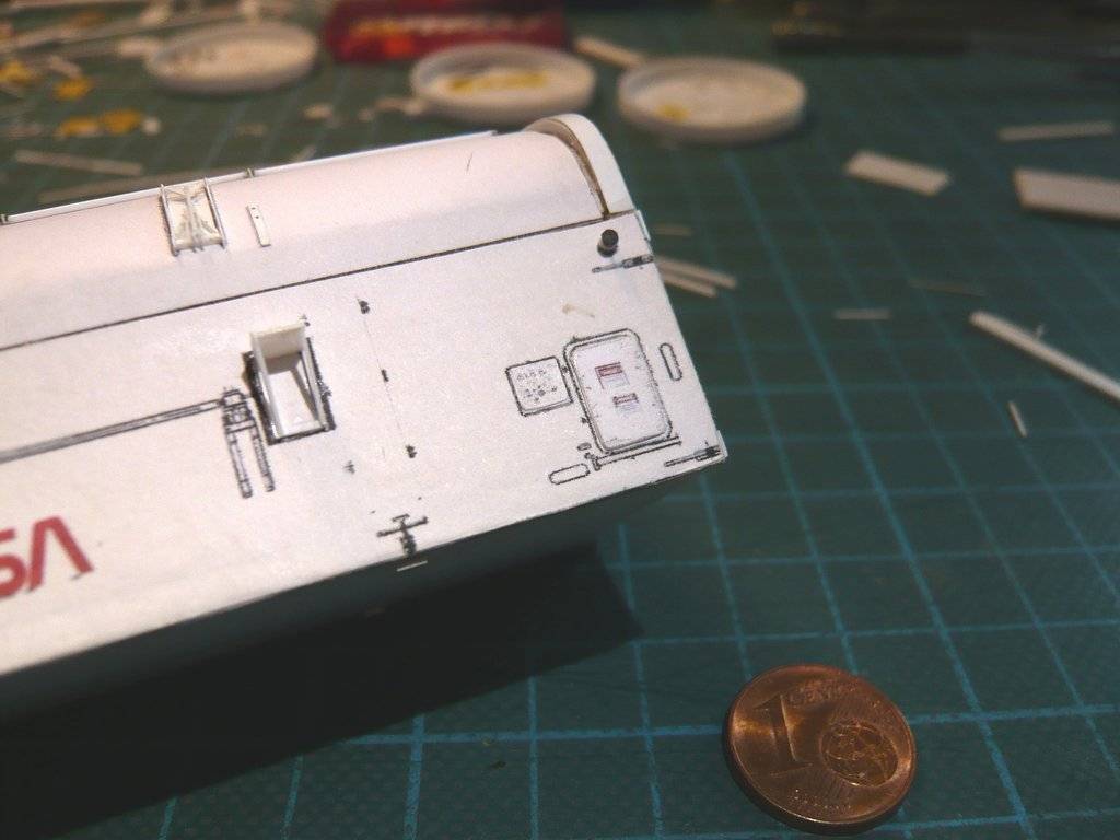
and thanks my friends for your staying interest  because I have seen you have been spying on my build again. because I have seen you have been spying on my build again.  Now that the Handrails are safely stowed away until they are glued, I once again looked at the various doors, hatches and instrumentation panels on the canister. Although these are only small optical details, they give the canister its own face and should not be missing. From these details I then printed out true-to-scale copies from original photos and glued them on. First, there's this Personnel Door on the Forward Bulkhead of the canister, 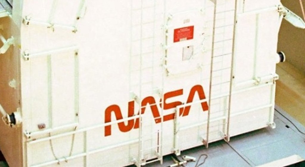 Source: forum.nasaspaceflight.com (STS-9, Ares67) which has to be tight and therefore quite robust, which is why I reinforced the thin paper a bit. The eight Handrails are then glued there too.  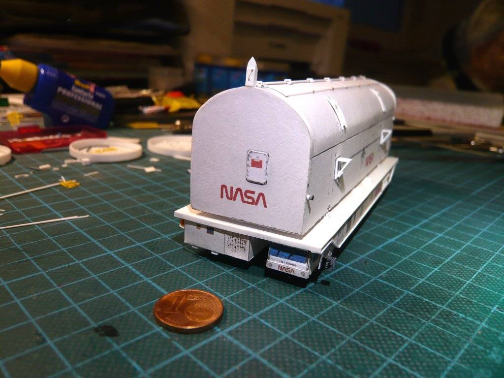 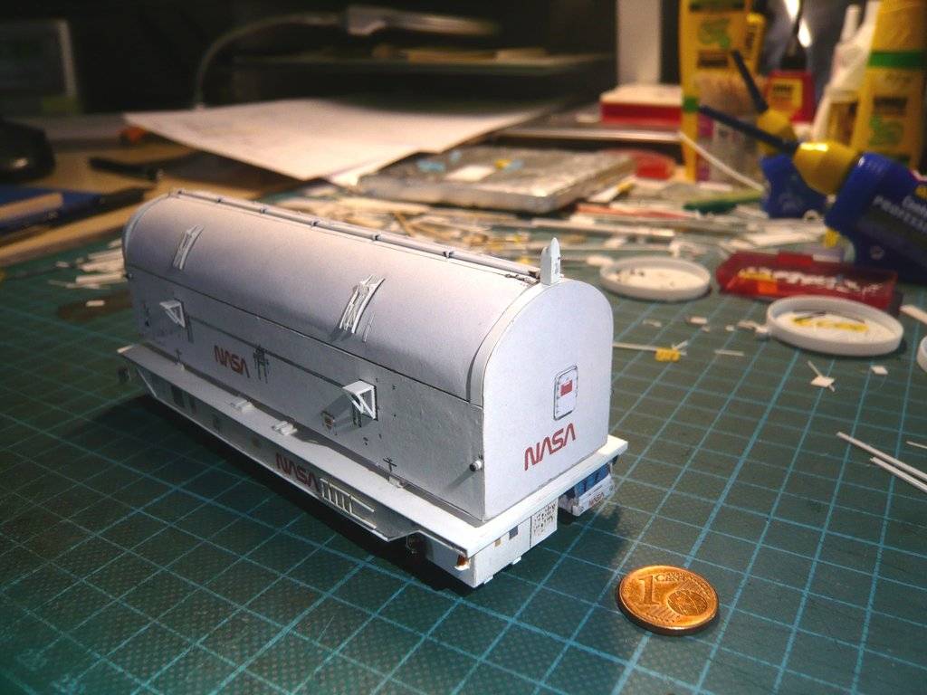 The two Ladders in the first image were only hung in the Horizontal Transportation Mode in the Processing Facility. Since they would have gotten in the way when the canister was hoisted up in the RSS Payload Bay, they were removed before transportation the upright canister to the launch pad. After the canister was hoisted the workers of the Can Crew could enter onto the top of it via a fold-out Payload Canister Access Platform while wearing fall protections, as I've learned from James MacLaren and Richard Chamberlain.  Source: James MacLaren, The Construction of Space Shuttle Launch Complex 39-B (Page 52) As one can see in this image and the next one, the canister is secured by "Umbilical cords" during the whole way from the Processing Facilities to the top of the RSS Payload Bay connected to the transporter. These are the two red hoses on the Port Side and this black cable bundle on the Starboard Side to ensure constant Clean room conditions inside the canister.  Source: NASA (STS-93) And thus to the respective interfaces on the Side walls of the canister, on which various Instrumentation Panels are located, via which the canister is connected with the associated Modules inside the transporter that I already have described in my Reply #2560.  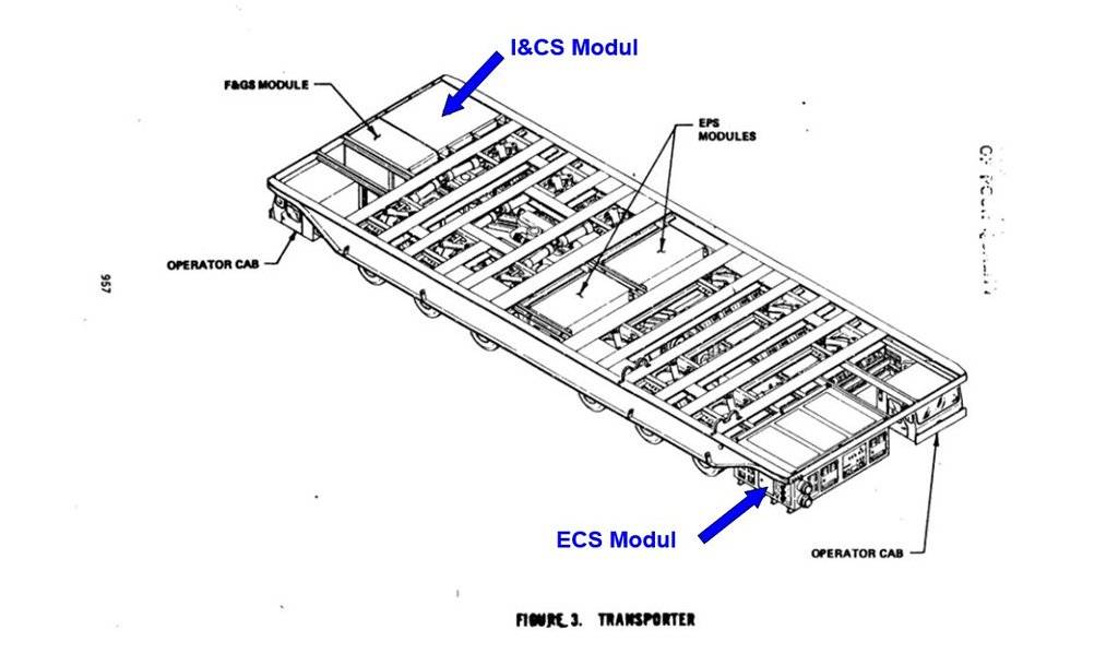 Source: NASA Conference Publication 2342 Part 2 (M. E. Donahue) On the Starboard Side there are three I&CS Instrumentation Panels and a ECS Panel in front of them.  Source: NASA (STS-135) The upper small panel is connected via five cables to the Instrumentation and Communication System (I&CS Module) at the rear end of the transporter, whereby the Climate and Clean room conditions inside the canister are constantly checked and monitored.  I'm not quite sure whether I'll attach these cables (Ø 0,1 mm) later.  In addition, I have to think about when I will attach which prepared fragile Assemblies (Door actuator, Screw jacks, etc.), since this will make handling the canister more and more complicated. In addition, I have to think about when I will attach which prepared fragile Assemblies (Door actuator, Screw jacks, etc.), since this will make handling the canister more and more complicated.  Here the four panels are already glued. 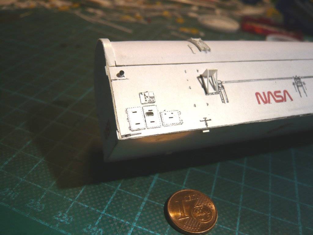 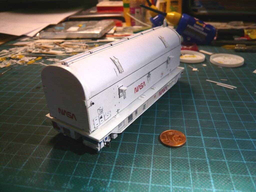 Further back on this side there is still this Access Hatch to the room below the payload bay to the Supply and Return Ducts, which via the red hoses are constantly connected with the transporter's Environmental Control System (ECS Module), which can be seen in the following photo. 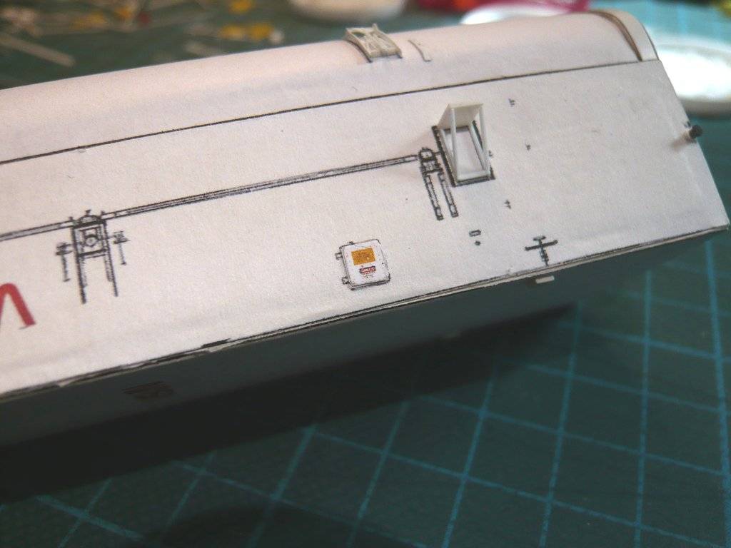 And so to the Port Side. At the forward end is a Personnel Door, which also leads to the room below the payload bay and the ECS duct attachments there, as well as the Pneumatic Interface Panel for the lower door seals. The front white Connection nozzle is connected to the ECS Supply Duct and the lower one to the ECS Return Duct. The red hoses are connected to it, which are connected to the ECS Module of the transporter and can be extended accordingly for the canister standing upright.  Source: NASA (STS-135)
__________________
Greetings from Germany Manfred Under construction: Launch Pad 39A with Challenger STS-6 (1:144)
|
|
#2804
04-02-2023, 06:39 PM
|
||||
|
||||
|
The door and the Interface panel are already glued, but the connection nozzles are still missing and will follow soon.
 For the red hoses (Ø 2,2 mm) I have already found a suitable cable with a corresponding diameter. 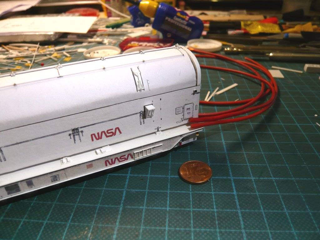 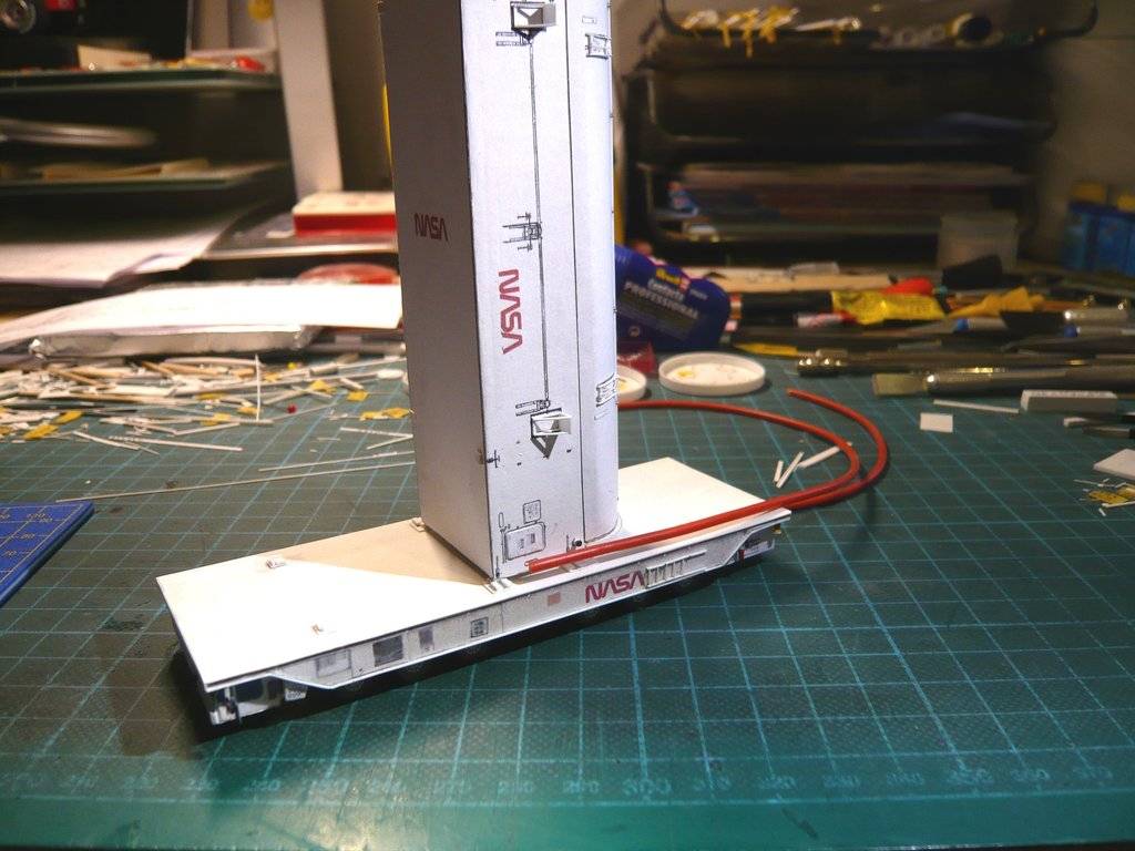 So it won't be boring.
__________________
Greetings from Germany Manfred Under construction: Launch Pad 39A with Challenger STS-6 (1:144)
|
|
#2805
04-08-2023, 06:43 AM
|
||||
|
||||
|
Hello everybody,
and thus to the ECS Supply and ECS Return Ducts of the canister, which are connected via the red hoses to the Environmental Control System (ECS Module) of the transporter. It's starting with the two white Connecting nozzles firmly connected to the canister with the Tube bows welded from five segments, whose dimensions I've determined from this photo.  Source: NASA (STS-130) There one can see that the connecting nozzles sit on thin Base plates (0,13 mm) and that the tube bows are attached to nozzles with Clamping rings, which is why I also will build this assembly from four parts, which will later be connected with the red hoses. For scratch building the Tube bows (Ø 2,5 mm) I was able to go back to my tried and tested Balsa Bending Technique (BBT) by using a Hot air pistol. 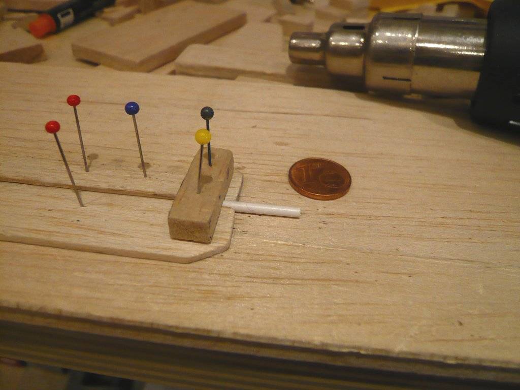 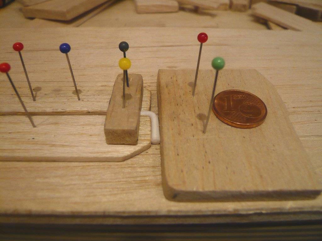 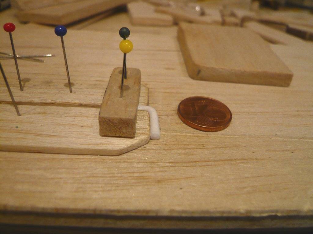  Next to the tube bows lie the Base plates (0,13 mm x 1,5 mm x 4,0 mm), on which the Connecting nozzles sit, as well as the Ring plates (0,15 mm x Ø 3,0 mm), which are glued between the nozzles and tube bows. 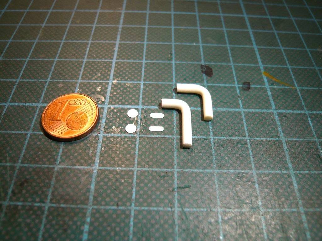 The tube bows now need to be shortened to their final lengths, which are different as you can see in this image.   Source: NASA (STS-104) But first I have to measure them again exactly, which will follow next.
__________________
Greetings from Germany Manfred Under construction: Launch Pad 39A with Challenger STS-6 (1:144)
|
|
#2806
04-11-2023, 06:03 AM
|
|||
|
|||
|
Über-cool work!!!

|
|
#2807
04-11-2023, 10:19 AM
|
||||
|
||||
 Marcell, Marcell,yep, I understand, that's scratch building's overkill! Please forgive me ...
__________________
Greetings from Germany Manfred Under construction: Launch Pad 39A with Challenger STS-6 (1:144)
|
|
#2808
04-11-2023, 11:09 AM
|
||||
|
||||
|
Hello everybody,
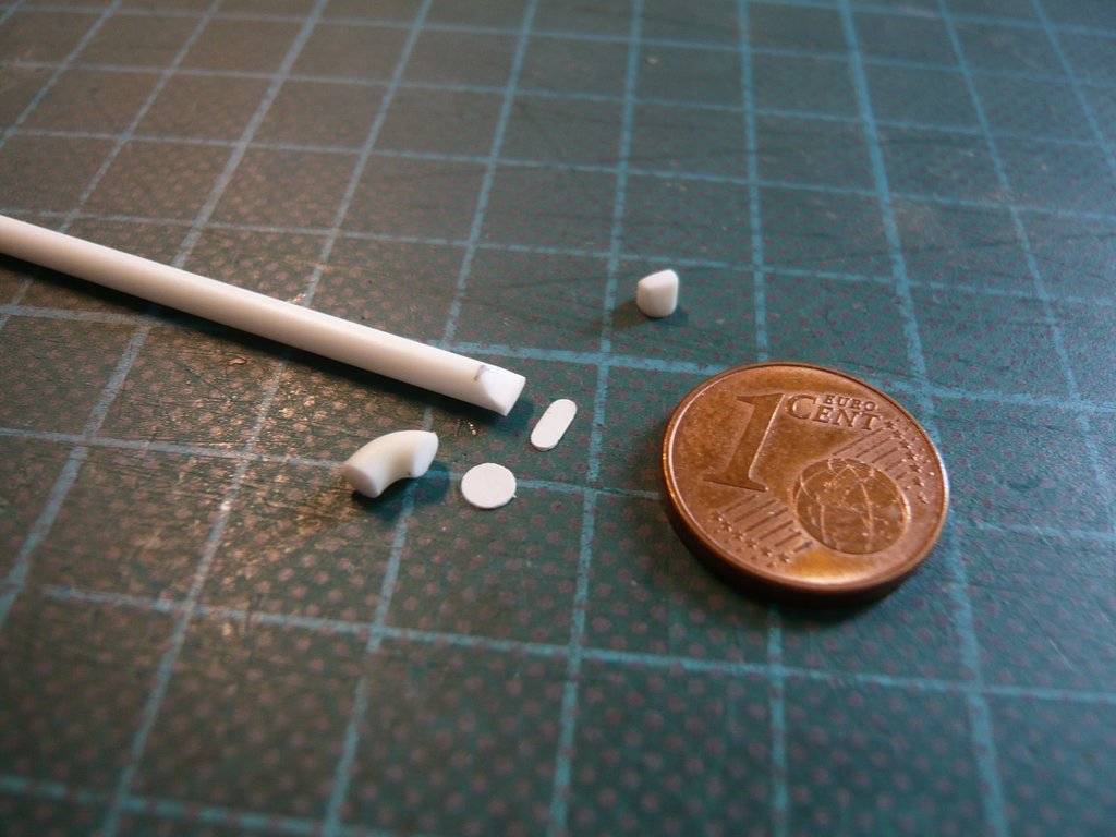
and thus to the shortening of the Tube turns for the two ECS Ducts, whose dimensions are summarized here again. Source: NASA (STS-104) In view of the small dimensions of the arches, it quickly becomes clear that after cutting the bent round rods (Ø 2,5 mm) to the different lengths, not much of them will remain, what becomes clear after the cutting marks been attached.  A firm fixation is required for cutting through the rod, which is why I clamped it in the Mini vise (Proxxon). Then the marking was carefully scored with the Mini saw (cmkkits.com) and the first cut (0,13 mm) was made, which was successful the first time.  After the fringe was gently deburred, 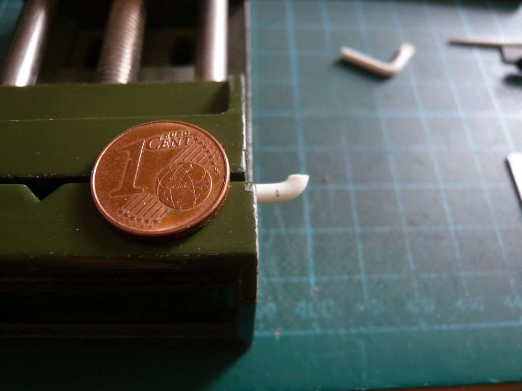 the second cut followed, 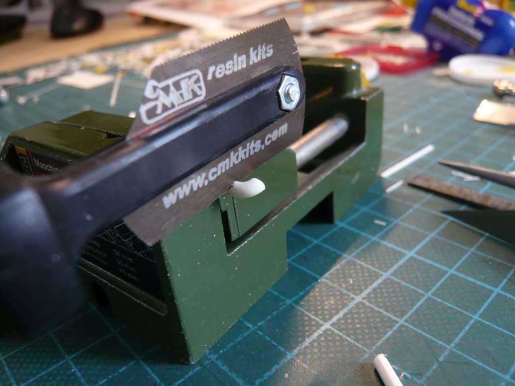 after which only this unwieldy little worm remained.   And while I was still smoothening this midget a bit, the bewitched mishap happened again that the damned thing slipped out of my fingers,  and flew away into the space between the container and the sideboard. and flew away into the space between the container and the sideboard.   Luckily I found it among the plates stored there and after a breather I was able to continue. But below the tube turns there are still these strangely shaped Connecting nozzles (ECS Ducts), which I racked my brains about making for a long time.   Source: NASA (STS-132) As one can see in the zoom, these ECS ducts have a narrow rectangular foot (1 mm x 3 mm) that rests on a base plate (0,13 mm x 1,5 mm x 4 mm), which widens in a funnel shape toward the tube turn to its diameter (2,5 mm). And in this change in shape from 3 mm (rectangle length) to 2.5 mm (diameter) is the difficulty for scratching the part.  In order not to have to file this part out of a round rod (Ø 3 mm) from solid, I tried to crush a round rod (Ø 2,5 mm) at the end with a flat pliers onto the rectangular cross-section (1 mm x 3 mm), which did not result in a satisfactory shape in the end.  
__________________
Greetings from Germany Manfred Under construction: Launch Pad 39A with Challenger STS-6 (1:144)
|
|
#2809
04-11-2023, 11:10 AM
|
||||
|
||||
|
But the flat crushing went much better with a round nose pliers, which was no less tricky because of that. But the result and the shape finally convinced me,
 here shortly before cutting off the tiny Duct nozzle. 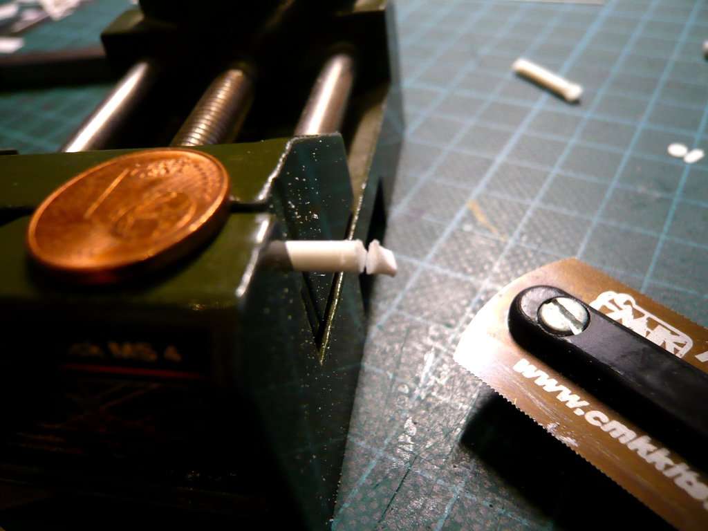 These are the four separate parts, 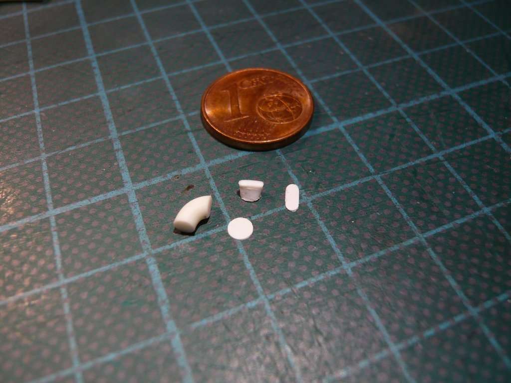 of which the duct nozzle was now glued to the ring disc (0,15 mm x Ø 3 mm) and aligned. 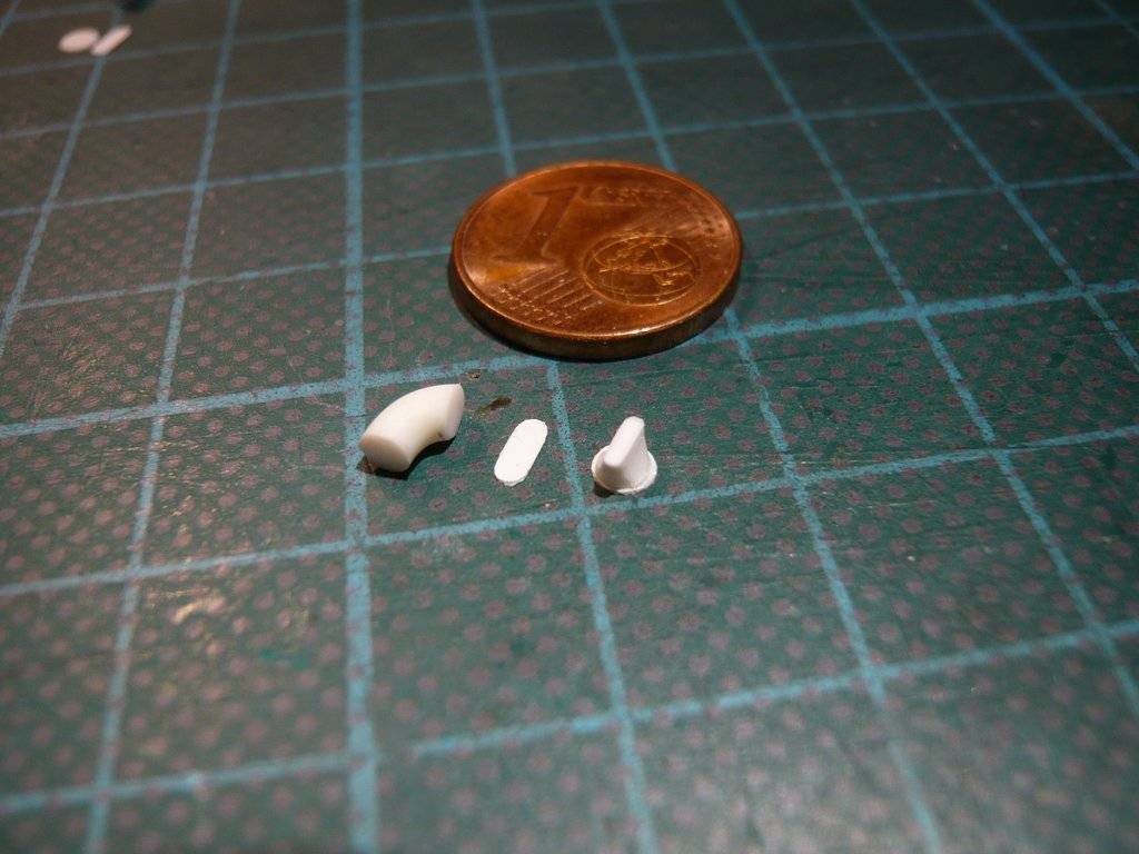 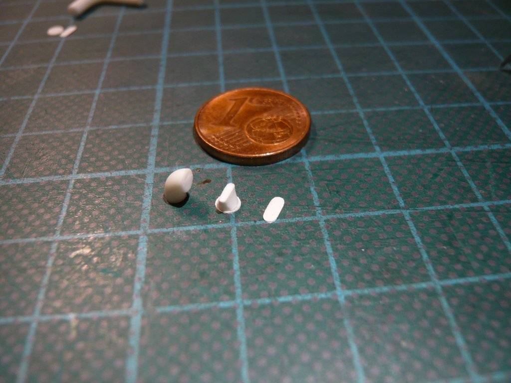 Then the tube turn was glued to the other side of the annular disc. 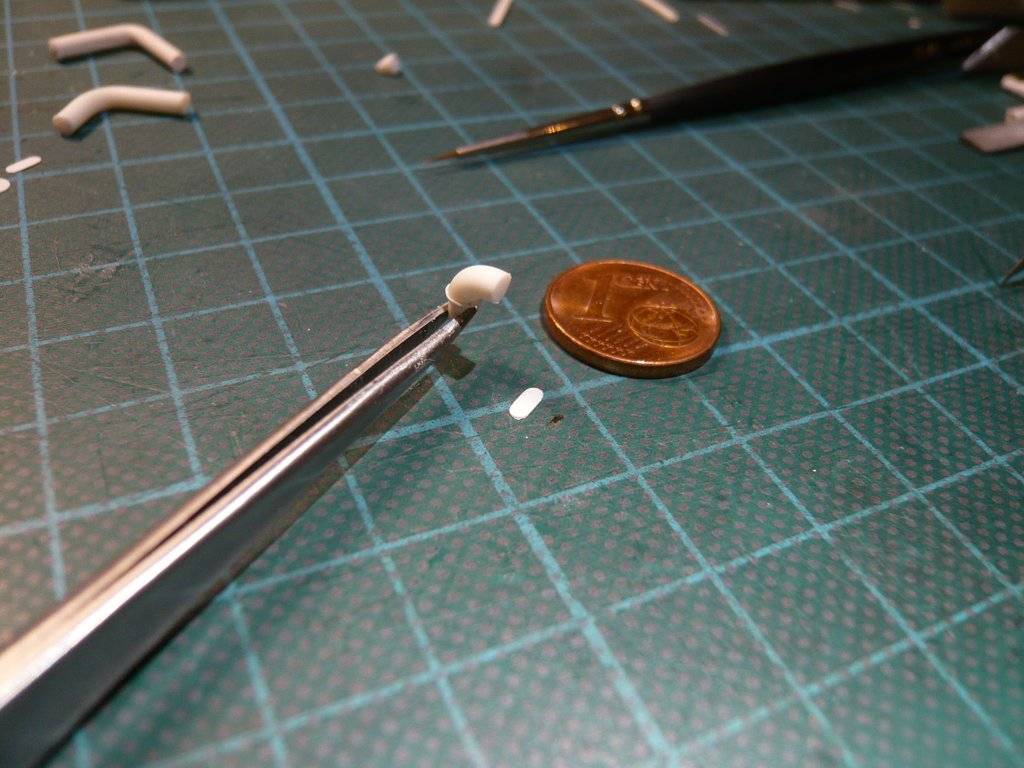 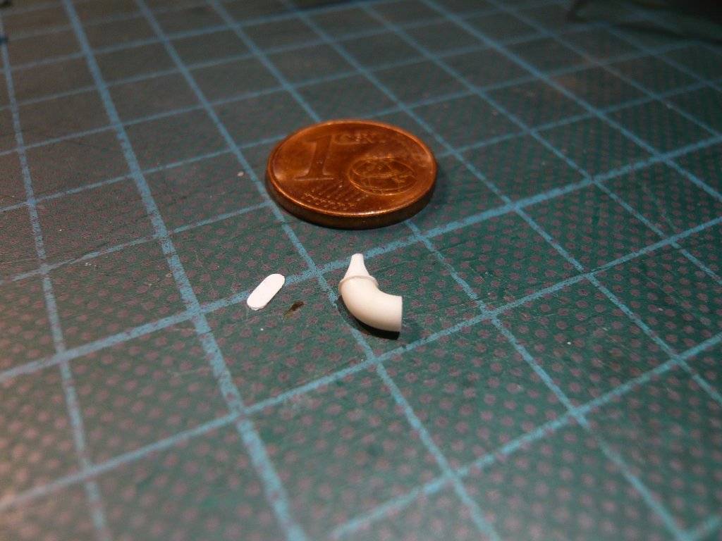 Finally, the trio was glued to the base plate, finally completing this elaborate detail. 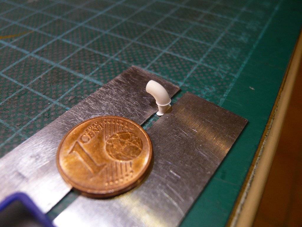  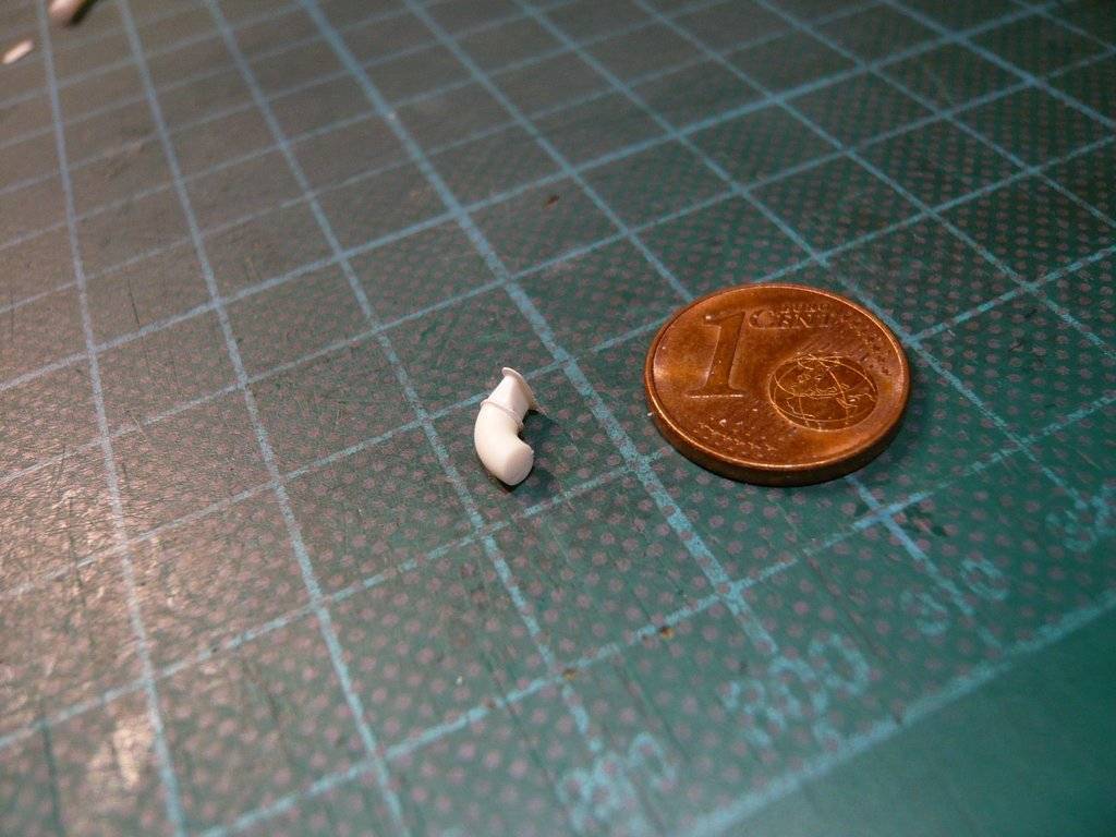 And finally the test fitting of the red hose between the ECS Return Duct and the ECS Module of the transporter, 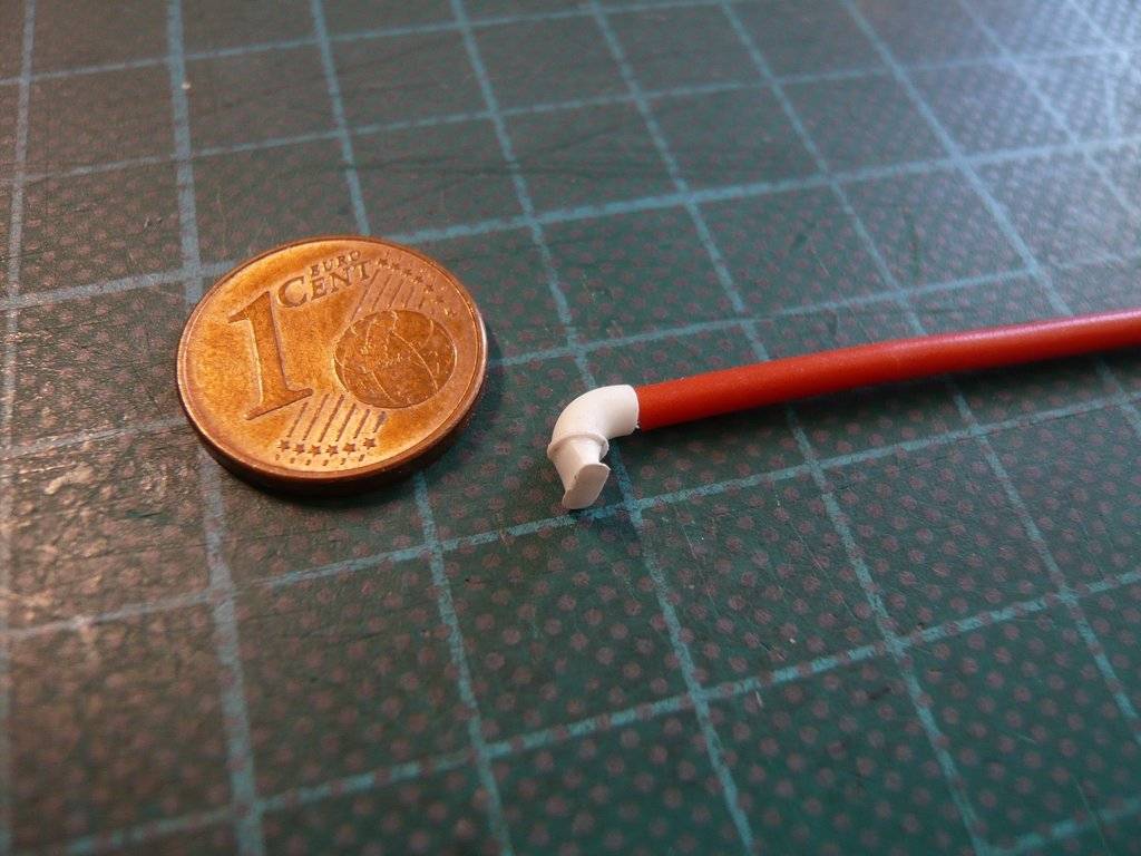 and here the test fitting of the ECS Return Duct on the Payload Canister.  And now the same procedure again for the ECS Supply Duct, wherefore however the tube turn on the connection duct has to be glued rotated by 90°.
__________________
Greetings from Germany Manfred Under construction: Launch Pad 39A with Challenger STS-6 (1:144)
|
|
#2810
04-18-2023, 03:34 PM
|
||||
|
||||
|
Hello everybody,
and after the same knitting pattern briefly to the announced ECS Supply Duct, for which the Pipe bend on the Connection nozzle has to be glued rotated by 90°, wherefore the parts on the right are already prepared. To the left is the finished ECS Return Duct. After the Connection nozzle was glued onto the Ring plate, 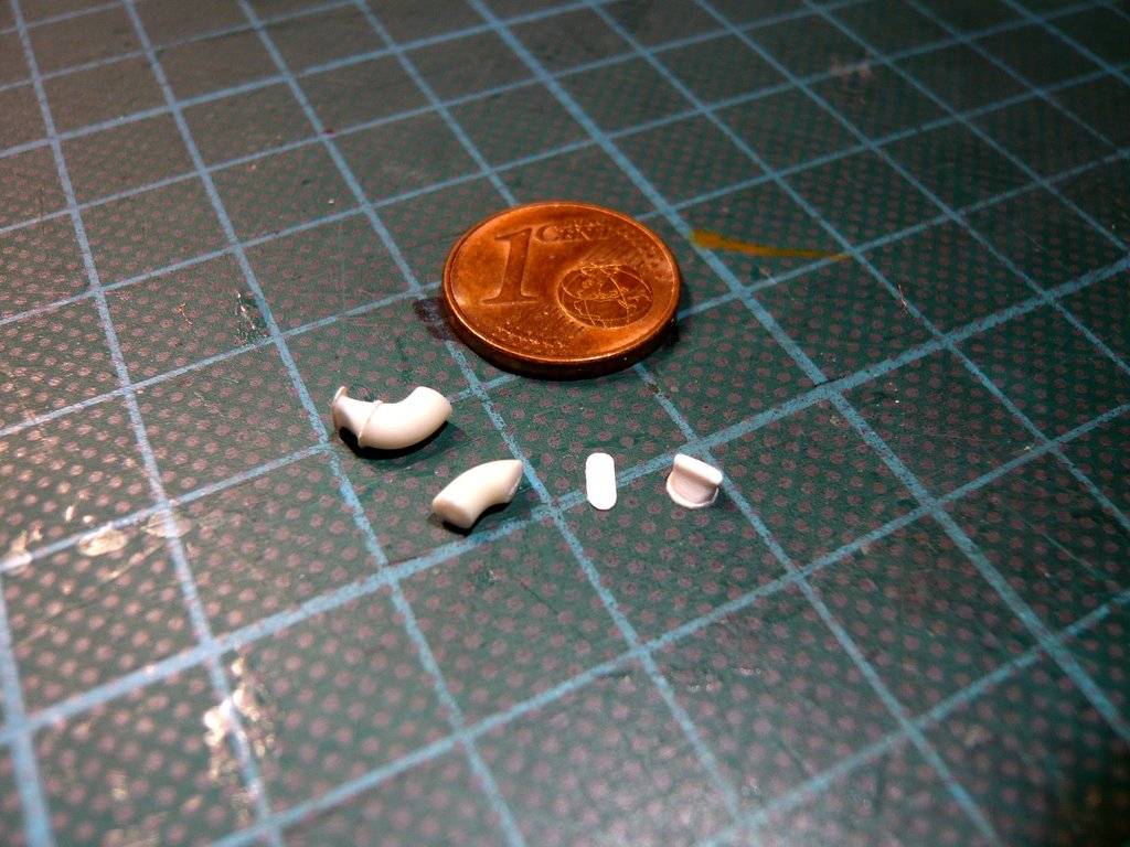 came the decisive step, in which this time the pipe bend had to be glued lengthwise with the foot of the connection nozzle onto the ring plate, 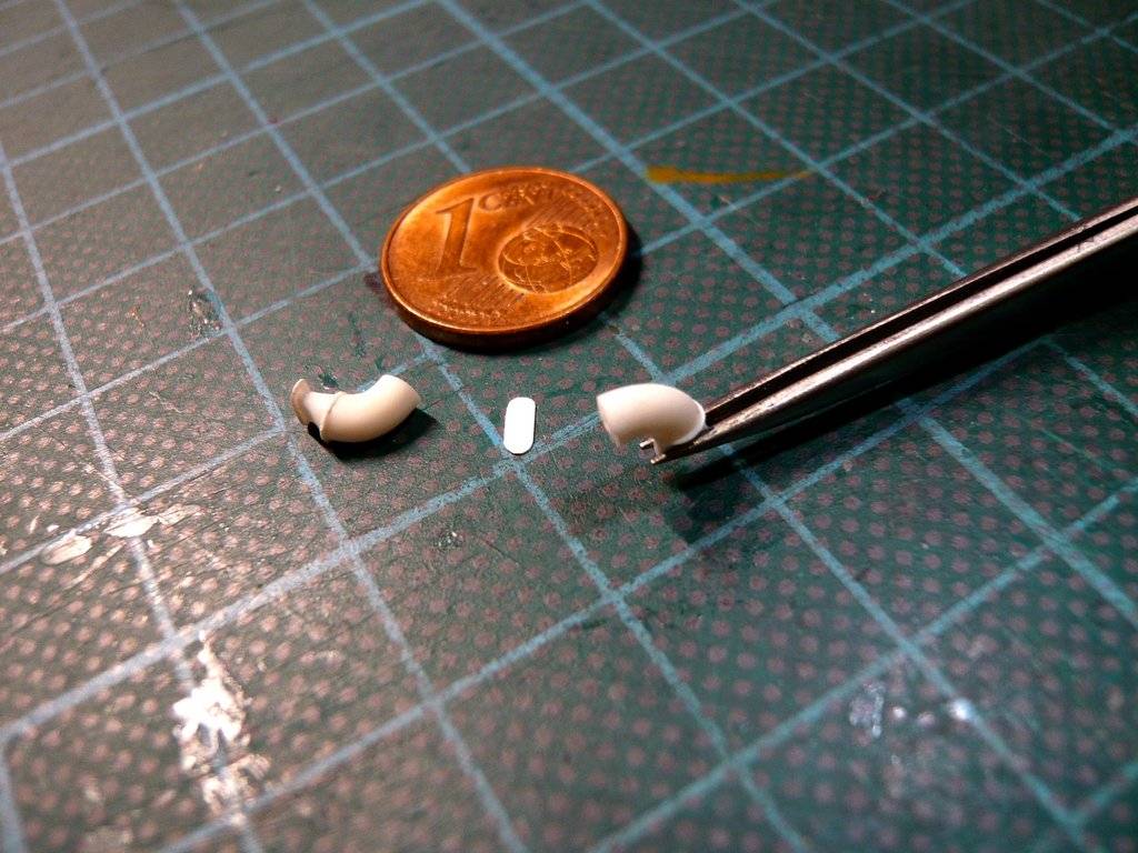 which was then glued lengthwise onto the base plate. 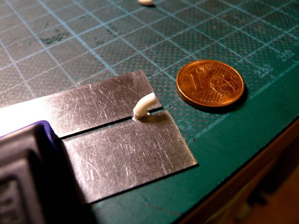 So both ECS Ducts are now completed. 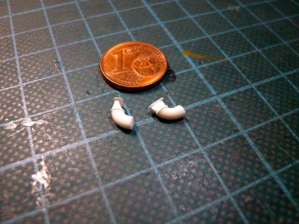 While this was the test fitting of the ECS Return Duct to the Payload Canister shown in the last post, 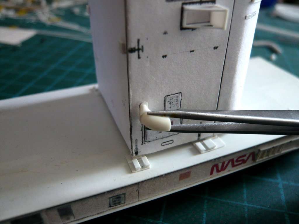 here now the test fitting of the ECS Supply Duct on the canister, which is laying below. 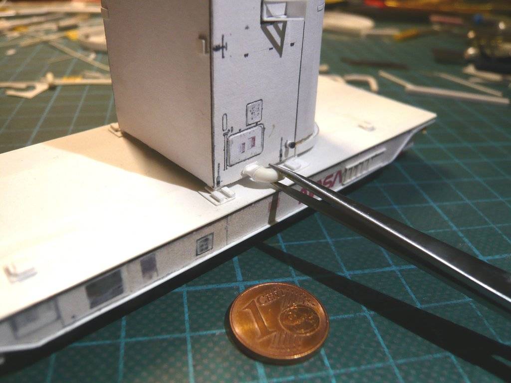 With this I can later show the canister standing upright on the transporter on the Diorama in front of the RSS, as can be seen on this image in Transportation Mode.  Source: NASA (STS-125) But both ECS Ducts are put aside for the time being and later glued onto the canister.
__________________
Greetings from Germany Manfred Under construction: Launch Pad 39A with Challenger STS-6 (1:144) Last edited by spacerunner; 04-19-2023 at 04:31 AM.
|
 |
|
|


 Linear Mode

