


|
|
|
#11
 04-05-2024, 05:13 PM
|
||||
|
||||
|
Hello everybody,
and now to the assembly order, which I thought carefully about.  Since my two Z-shaped brass struts are supposed to go through the probe cube, it quickly became clear that I wasn't allowed to glue the cube together on all sides yet otherwise it would not be possible to thread the struts through.  That's why in the following picture I tried to mark the individual steps in order with arrows, which may not be understandable straight away,  which is why I would like to briefly explain the steps. which is why I would like to briefly explain the steps. 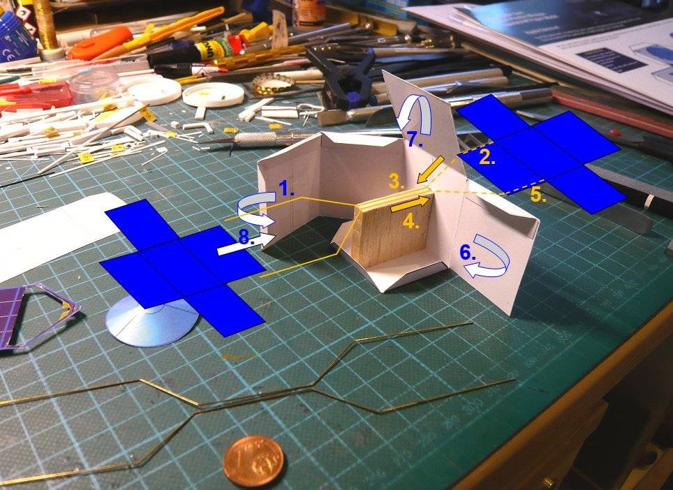 In order to still have enough freedom of movement when threading the struts, I can in the 1st Step first just only glue the two rear side walls to the floor and the Balsa support.  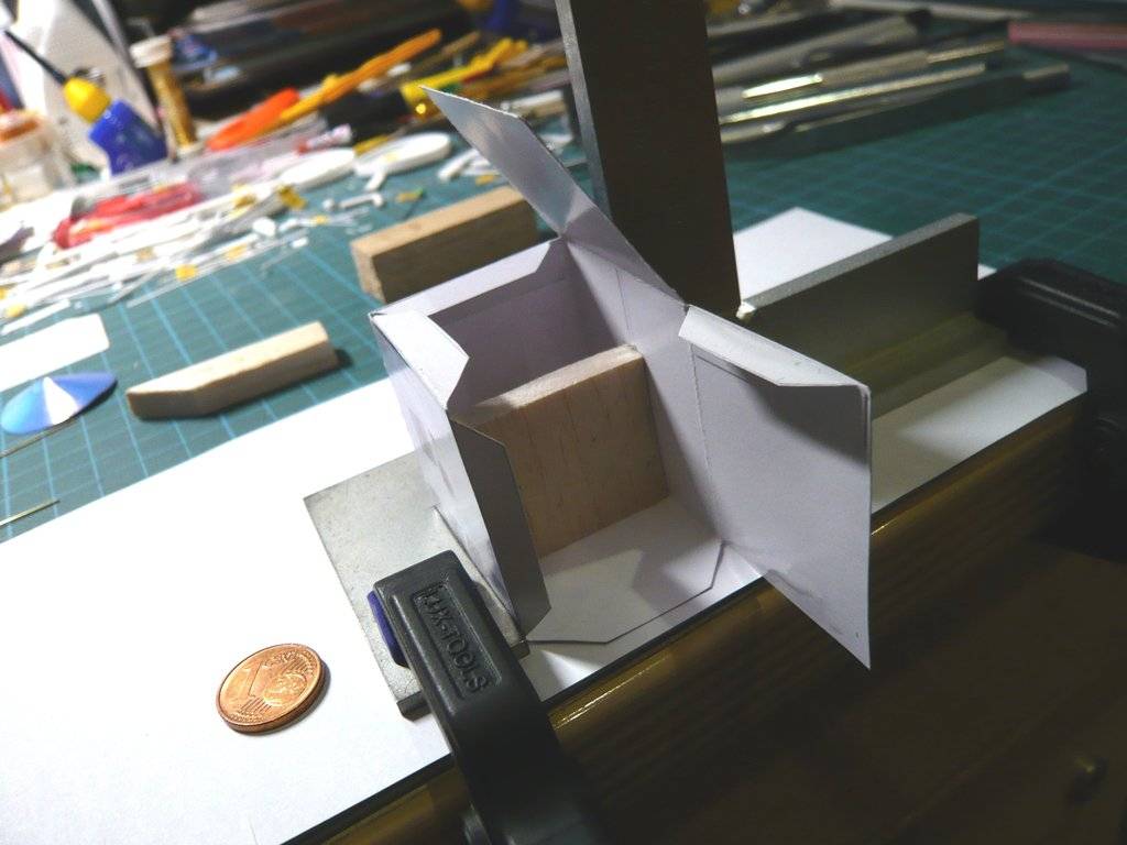 In the 2nd step I only glued the end of the brass strut onto the back of the upper panel with UHU CA, because I might want to leave out the white paper triangle.  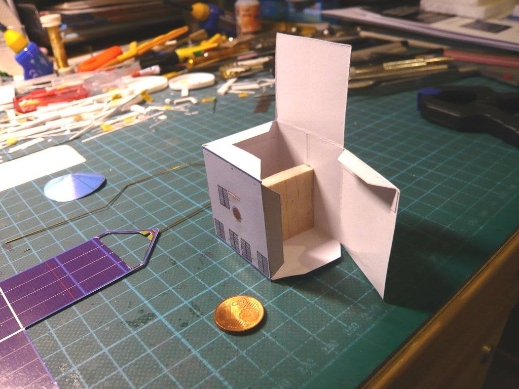 In order to be able to handle these bizarre structures when threading through the struts, I cut two Styrofoam blocks to the required height to support the panels. 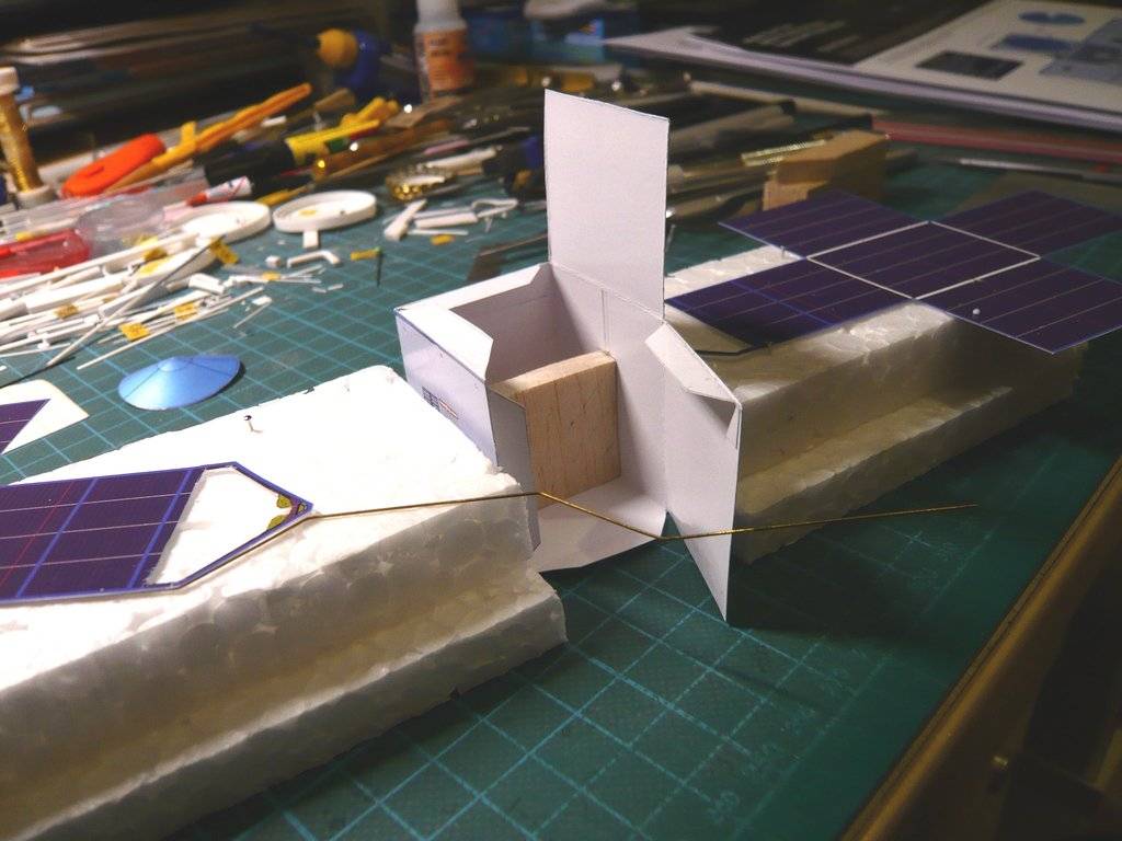 In the 3rd Step then followed the careful threading of the glued strut first through the front side wall and then by turning the rear support so that the strut could also be threaded into the rear side wall and then could carefully pulled through, 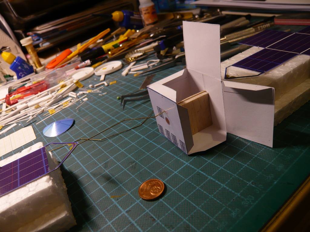 which actually worked.  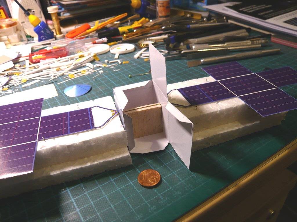 The other panel is only temporarily placed in these images. 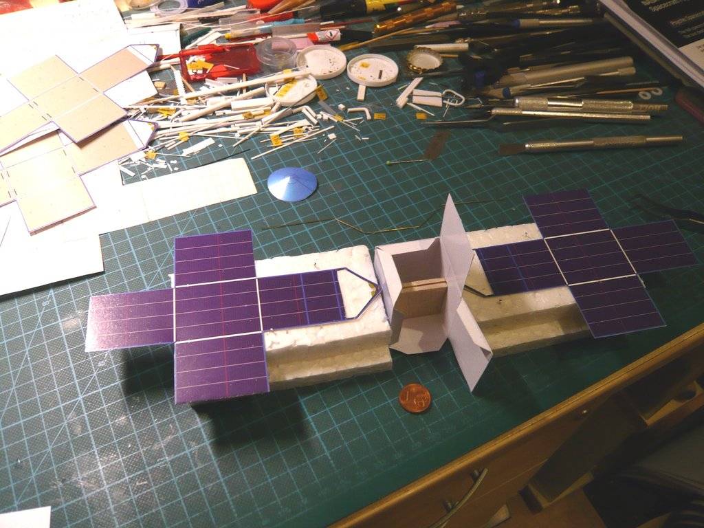 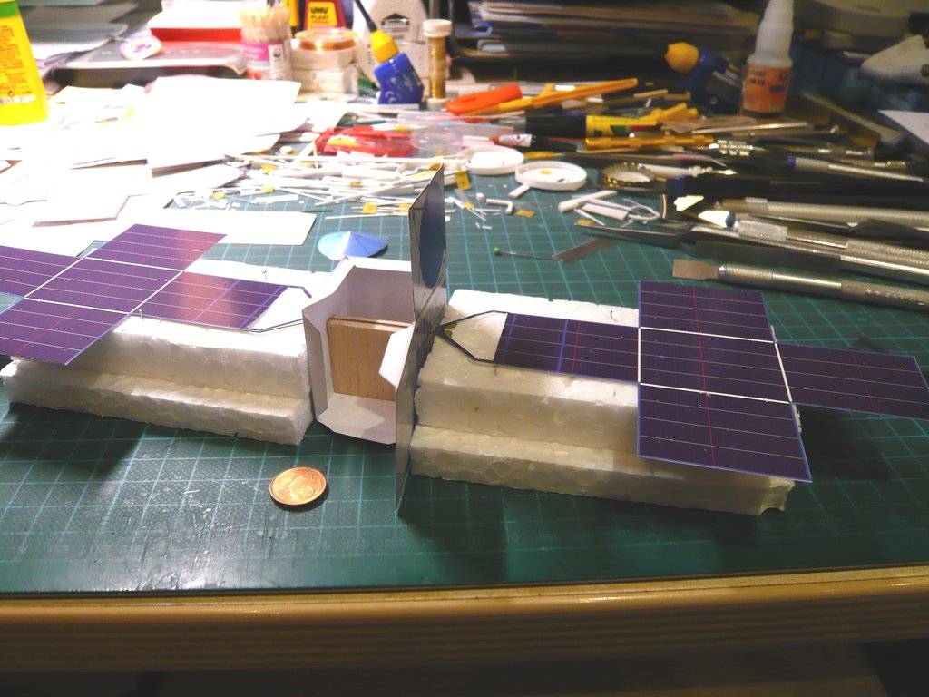 With this panel and the Steps 4 to 8 it will continue tomorrow.  I hope you don't get confused. 
__________________
Greetings from Germany Manfred Under construction: Launch Pad 39A with Challenger STS-6 (1:144) 
|
|
#12
04-06-2024, 03:02 PM
|
||||
|
||||
|
Hello everybody,
today was the day, and when I've turned the probe around full of curiosity I was pleasantly surprised that both Solar panels remained almost horizontal, especially since both were only glued on one brass strut, wherewith my idea actually proved to be a viable solution.  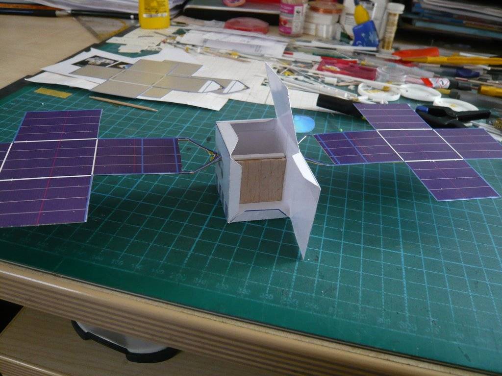 In Step 6 the side wall could now be glued,  and then also the top finish (Step 7). However, I don't like the blue X-Band High Gain Antenna yet,  and since it is covered with foil in the original probe anyway, I tried that too and cut the part out of thin aluminum foil.   I then stuck the foil with CA onto the cone, which looks better to my taste. However, I will not glue the X-Band Antenna firmly onto the probe until later, as I would like to add a few details that have so far only been hinted at in the paper kit.   I've then turned the probe over again and glued the remaining brass struts onto the undersides of both panels.  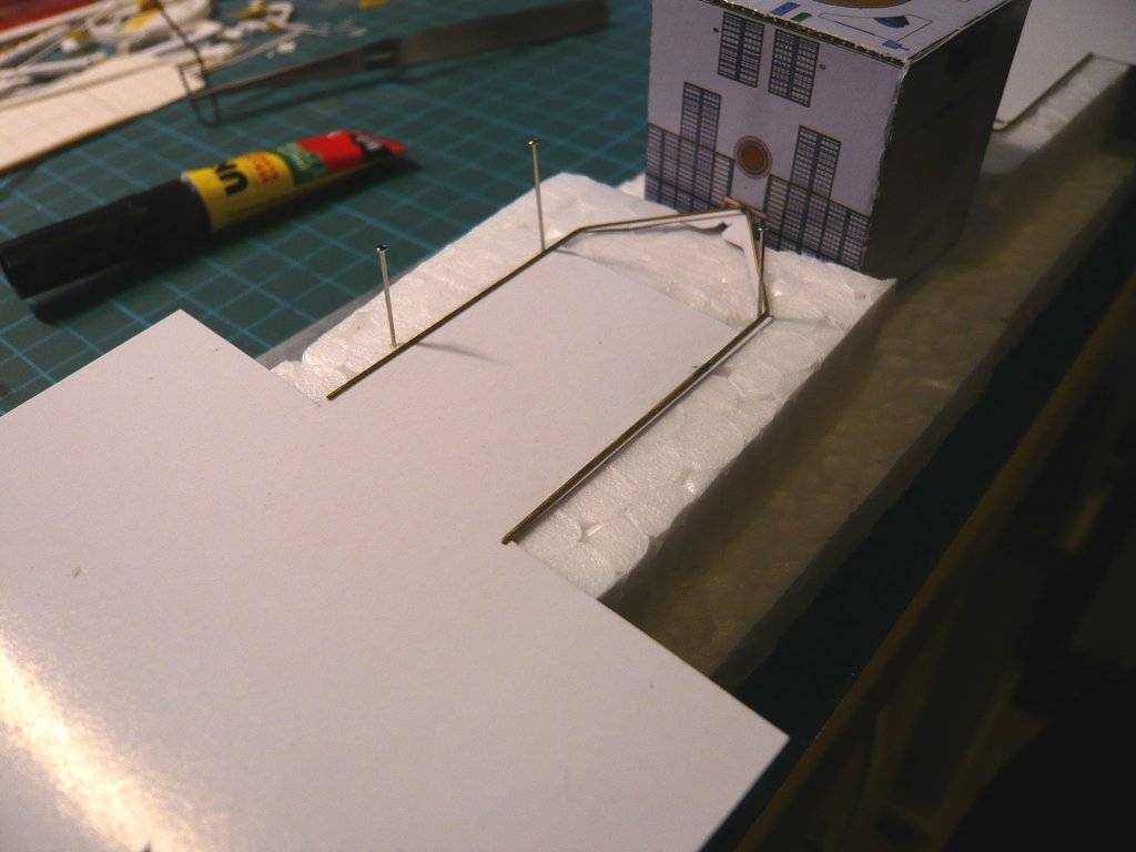 Now that both panels were sufficiently stabilized, I turned everything over and took a closer look at all again.   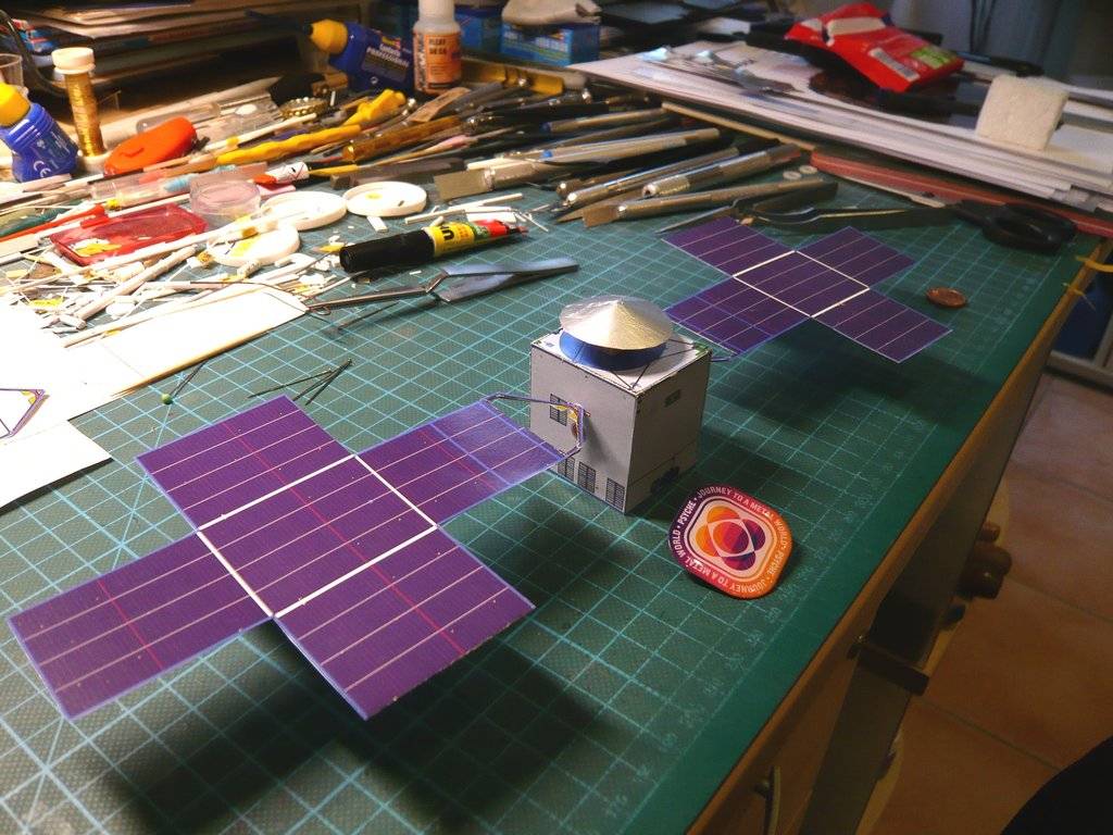 Afterwards I decided to remove the paper covers of the struts because this look corresponds more to the original and will only glue the downscaled front covers, 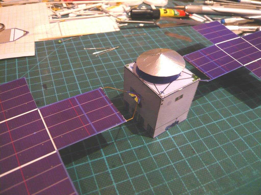 which I've scaled from the video shown at the beginning. 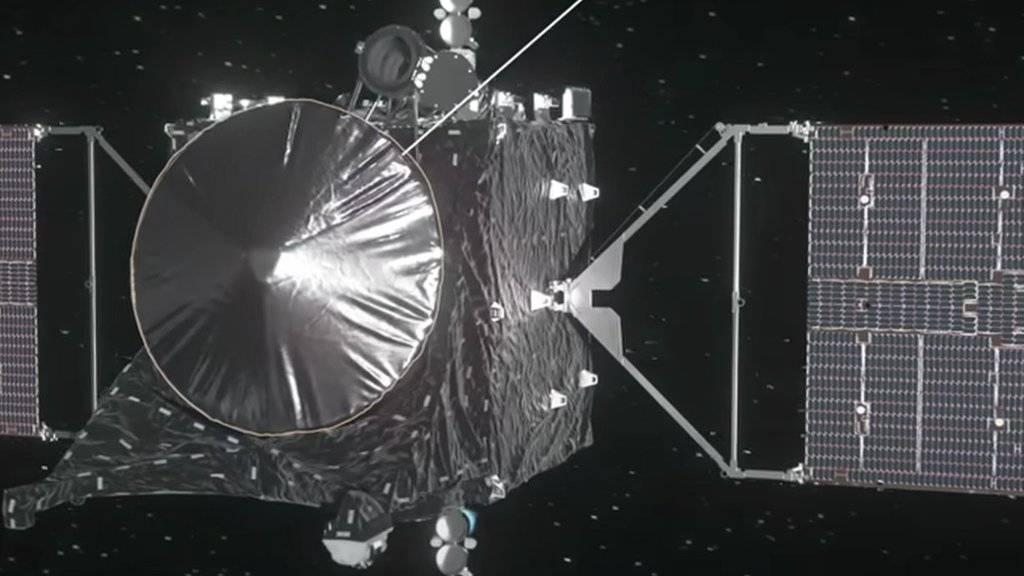 Source: Official NASA Trailer (2:00) Now the crossbars are still missing on both panels, which I have therefore already removed from the kit and will also replace with brass wire, as well as some details such as the Rod systems in the two corners, as well as Thruster and Spectrometer, which I could possibly hint at.
__________________
Greetings from Germany Manfred Under construction: Launch Pad 39A with Challenger STS-6 (1:144) Last edited by spacerunner; 04-06-2024 at 03:29 PM.
|
|
#13
04-07-2024, 05:49 PM
|
||||
|
||||
|
Hello everybody,
today I dared to the cross struts (brass wire Ø 0,5 mm), but gluing them in turned out to be extremely difficult, which required a lot of sensitivity.  The top priority when gluing was a secure bearing and locking of the probe and panels so that nothing could slip.  Since the gluing had to be done with UHU CA, the strut could initially only be done on the back side. So that after the strut moistened with CA had been positioned accurately, it could be carefully placed on the front side after a short time to set, I glued a tape strip there as a shelf, what has also proven successful.  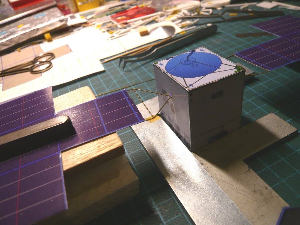 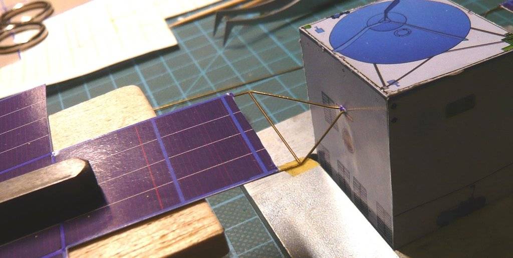 After carefully removing the tape strip, the strut could also be glued at this point by dabbing it with CA using an acupuncture needle. The small triangular strut on the probe wall was then glued onto the struts, wherewith this side was completed. 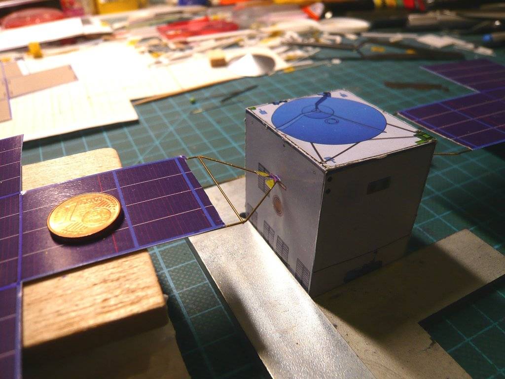 The crossbar on the other side was glued in the same way. 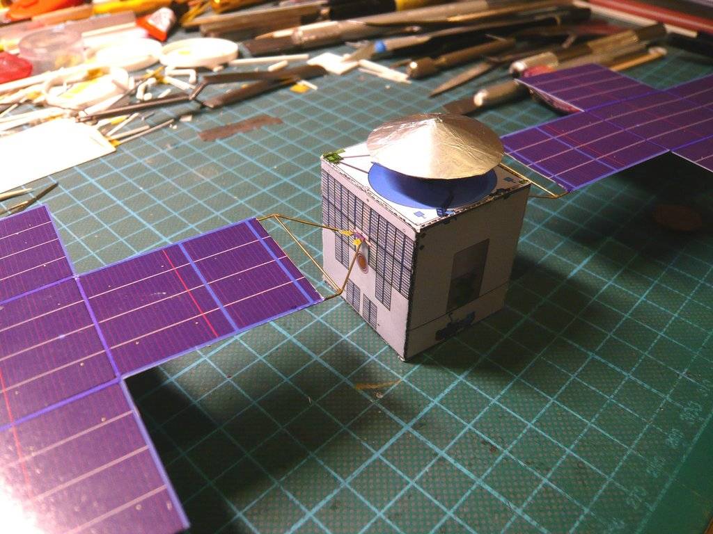 Maybe you probably haven't noticed yet, I've colored the white edging of the middle panel area blue, which I like better that way.
__________________
Greetings from Germany Manfred Under construction: Launch Pad 39A with Challenger STS-6 (1:144)
|
|
#14
04-15-2024, 09:16 AM
|
||||
|
||||
|
Hello friends,
the longer I look at the greatly simplified Solar probe body from the Paper Kit and compare it with NASA photos and videos, the more things I notice that I don't like yet, which is why I decided to scratch several details that were only printed and thereby refine the probe's outfit a little. The X-Band High Gain Antenna shown in the kit as a flat cone actually has, like all space probe antennas, an inwardly curved, concave shape and is covered by a foil, whereby it because of the three struts underneath just appears as a flat cone, which I have already covered by gluing on aluminium foil. That's why I first stuck over the blue outline of the antenna on the top of the probe, which is simply wrong there and is just irritating.  But I could have saved myself that, because as you can see on NASA videos, the sides of the probe body are partially covered with reflective silver and black foil, which is why I came up with a new idea.   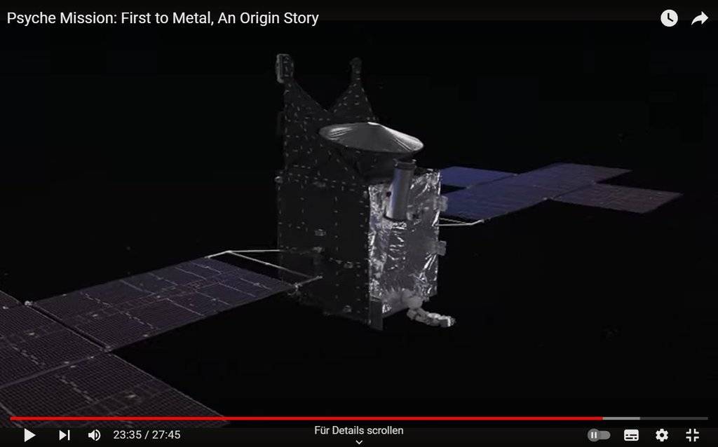 And since I like to use different materials, I looked for suitable stuff in my stocks and found some too, 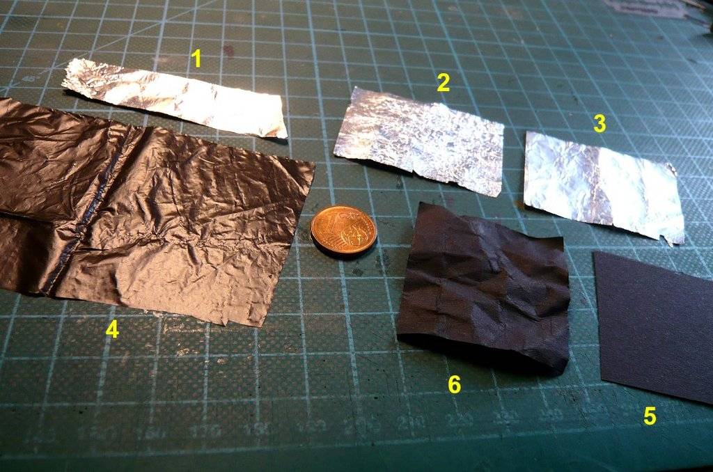 such as: 1 Aluminum household foil, smooth, shiny front 2 Aluminum household foil, heavily creased, matt shiny back 3 Aluminum household foil, slightly wrinkled, matt shiny back 4 Plastic film (robidog.com),  , is certainly familiar for German dog owners. , is certainly familiar for German dog owners.  5 Construction paper, black, smooth 6 Construction paper, black, slightly creased Now I just have to decide, although I'm leaning towards aluminum foil and paper because it's easier to glue. Then I looked closer at the rod constructions at the two corners,  which are also covered, but I still have to take a closer look at them. At the top of the wider construction there is a Gamma-ray spectrometer for analyzing Gamma-ray spectra. which are also covered, but I still have to take a closer look at them. At the top of the wider construction there is a Gamma-ray spectrometer for analyzing Gamma-ray spectra.  In order to be able to scratch these constructions, I first have to determine their dimensions, which is known to be a stressful business of measuring and scaling based on a reference dimension, At least I've already started with the wider construction. The one on the opposite side is narrower, for whatever reason.  Source: Arizona PBS This will be another stressful torture for my eyes again,  but don't panic, they always survived it so far. but don't panic, they always survived it so far.
__________________
Greetings from Germany Manfred Under construction: Launch Pad 39A with Challenger STS-6 (1:144)
|
|
#15
04-16-2024, 08:15 AM
|
||||
|
||||
|
Hello everybody,
and since I've just gotten my head around my approved scaling procedure again, I want to continue straight away and have done the same on the opposite side with the narrower rod, which is also covered with foil. It is always important to define a reference dimension for scaling all other dimensions, in this case the height of my model probe body.  In addition to the dimensions of the rod systems, I also have the dimensions of the Deep Space Optical Communications (DSOC) System and the two probe engines (Hall-effect Thrusters) determined. The DSOC dimensions can be determined a little more precisely in this image, which is why a plausibility analysis is still advisable between similar images to select the final dimensions. 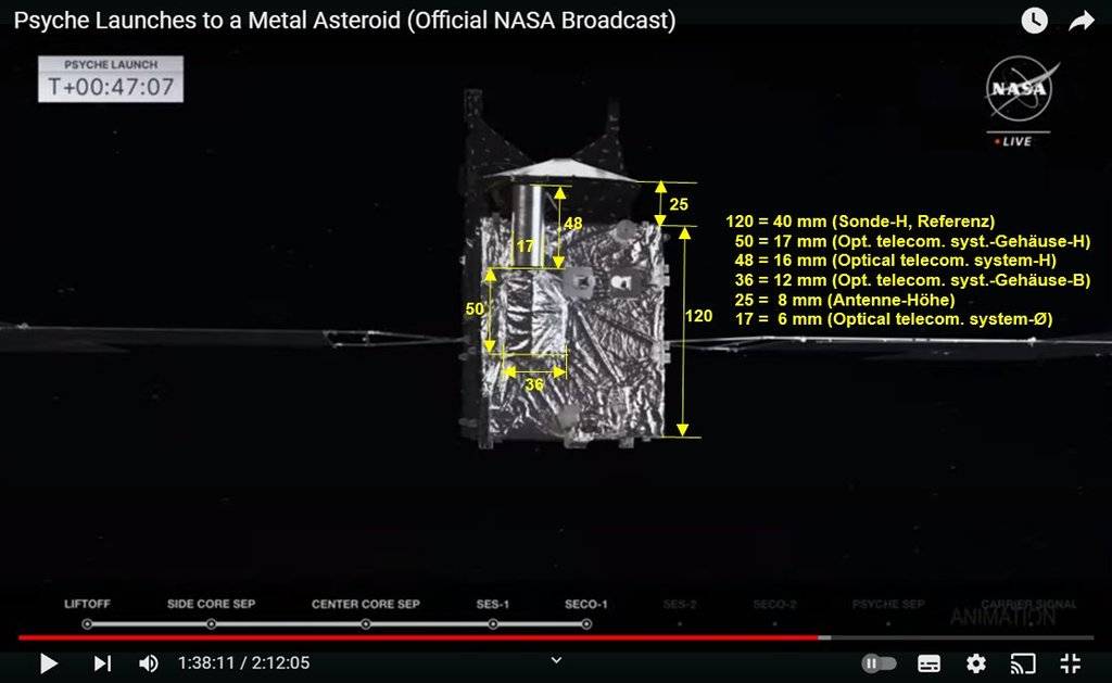 At this point I would like to point out to anyone interested this video image (1:36:22), where based on this model the individual parts of the Psyche probe, are explained clearly, which was very helpful for me in terms of overall understanding.  If you want to watch the whole video from the beginning, you should skip the meaningless opening credits by clicking the next linked image and scroll to this point at the timeline (1:30).  On the back of the probe there is this covered transverse rod system, which connects the two side rod systems. 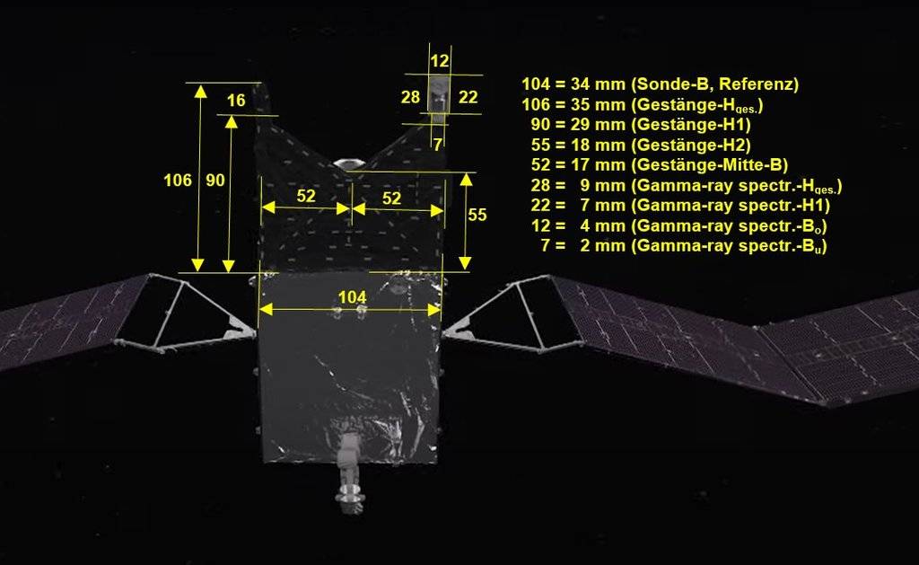 With these dimensions I can now create assembly sketches for all three the rod systems and for the claddings. And then we'll see.
__________________
Greetings from Germany Manfred Under construction: Launch Pad 39A with Challenger STS-6 (1:144)
|
| Google Adsense |
|
#16
04-17-2024, 05:03 PM
|
||||
|
||||
|
Hello everybody,
I still found a better material for the dark covering of the probe sides and rod systems. I had an appetite for After Eight once again, and when I unpacked it I had the little wrappers between my fingers and immediately thought Eureka - I have it!  The outside of the cases is matt black and the inside is glossy. And after I've crumpled up and then unfolded it again I think that this variant is the best solution. Then I thought about how best to scratch the foot of the X-Band High Gain Antenna,  but so far I haven't been able to find a useful photo that would show it in more detail. but so far I haven't been able to find a useful photo that would show it in more detail.Since you can hardly see the base anyway, I first cut a small cylinder out of a discarded ballpoint pen and stuck it under my existing antenna, what I also wanted to cover with aluminum foil. Then in this image it almost looked to me as if there was a cone-shaped cover beneath the antenna,  which is why I've enlarged it again, which seems to confirm my suspicion. 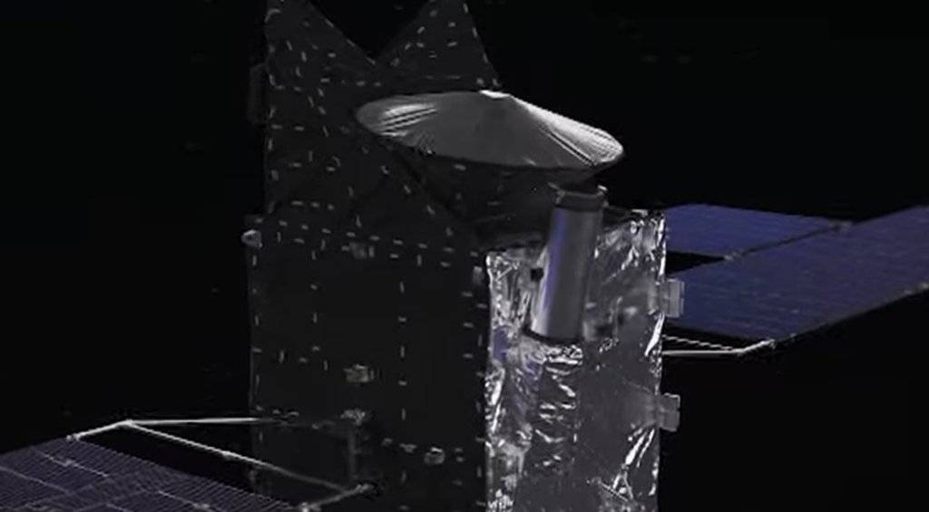 That's why I covered this paper lampshade with foil,  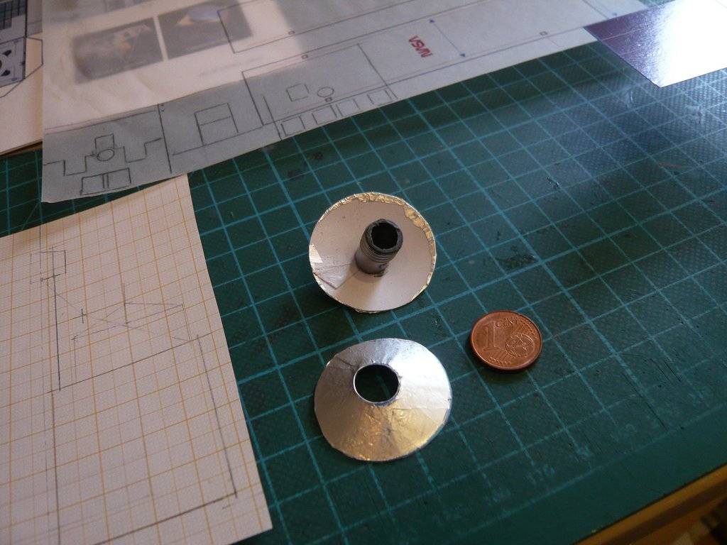 and glued from below over the base against the bottom of the antenna.  Here the antenna, covered in this way, is only temporarily placed on the probe, but that still doesn't convince me.  As one can clearly see on this model, the entire lower part of the antenna is loosely covered with dark foil.  That's why I'm going to rethink the entire cladding of the space probe including the rod systems and use both shiny aluminum foil and the After Eight paper.
__________________
Greetings from Germany Manfred Under construction: Launch Pad 39A with Challenger STS-6 (1:144)
|
|
#17
04-19-2024, 04:27 PM
|
||||
|
||||
|
Hello everybody,
Brevity is the soul of wit! By using the laboriously determined dimensions of the cladded rod systems I've created this drawing on a scale of 1:1,  with the help of which I can now first cut the claddings of the rod systems. For the rods themselves I will use steel wire (Ø 1 mm). That's it for today, I have to go to bed sooner again. 
__________________
Greetings from Germany Manfred Under construction: Launch Pad 39A with Challenger STS-6 (1:144)
|
|
#18
04-22-2024, 08:55 AM
|
||||
|
||||
|
Hello everybody,
today it was time to implement the sketched parts of the rod systems and their claddings, whereby I changed my plans again a bit and because of the easier gluing of the Foil cladding will not use steel wire but plastic round rods.  First, as a test, I inserted a rod Evergreen Styrene Rods ((Ø 1 mm) of the rear rod system into the pre-drilled holes in the probe top, down to the ground, 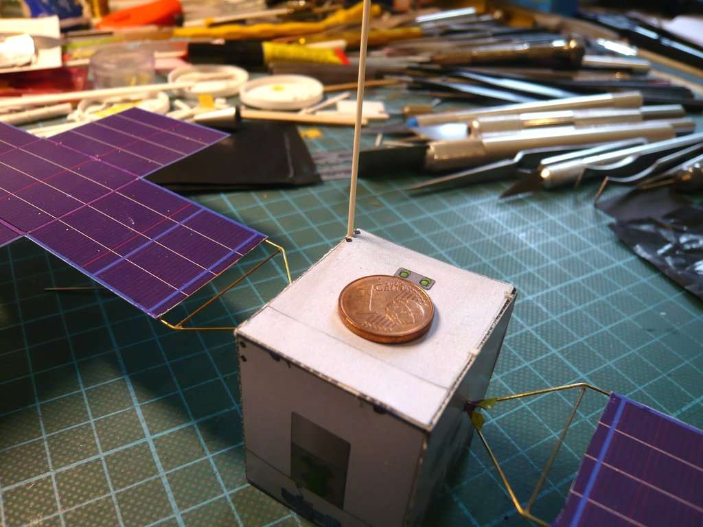 and then cut both rods to the required length (40 mm).  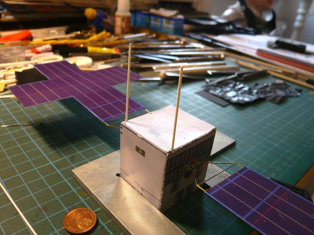 Then I thought about the fact that for the stability of the entire frame it would be useful to glue a connecting plate made of cardboard (0,9 mm) between the two rods on which I could then stick the black After Eight paper on both sides as a cladding, which would probably be the easiest solution.  Said and done!  Meanwhile I also decided to make the entire cladding from three parts, which are then glued one after the other, starting at the back. To do this, I first transferred the back onto the black paper and cut it out,   and after crumpling it was glued to the back of the rod system.  Finally, I also tried adding the white markings that can be seen on all sides of the claddings.  Source: wikimedia.org For this I used a white permanent marker (Montana Acrylic), which I tried out first. 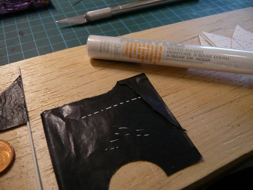 And since the dashes on the smooth paper are also smudge-proof, I then marked both sides of the rear panel, which is not that easy as the marker sometimes fails and has to be shaken again.  And this is what the result looks like from both sides, which I can live with.   Now I can make the side claddings in the same way and then glue.
__________________
Greetings from Germany Manfred Under construction: Launch Pad 39A with Challenger STS-6 (1:144)
|
|
#19
04-27-2024, 04:26 PM
|
||||
|
||||
|
Hello everybody,
for a change, today I dealt with the covered the X-Band High Gain Antenna again and initially replaced its surface with a more shiny silver aluminum foil. 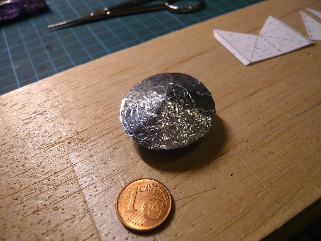 Then I've thought about how I could scratch the continuous all-round covering of the antenna below the cone, by using dark paper (After Eight), which on this image could be seen more clearly than I had previously recognized. 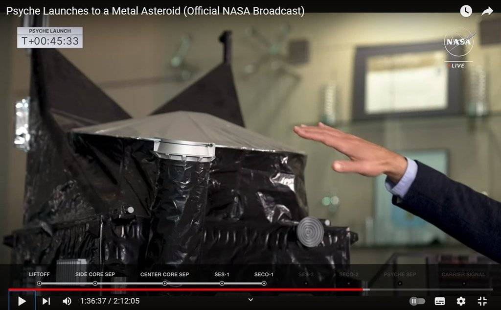 Due to the slight inclination of the antenna, I needed the unrolling of this fairing, which I've fiddled with for a while. To do this, I first cut a strip of paper the length of the circumference of the antenna (Ø 30 mm), which had to be 100 mm. I then rolled it up and placed it around the antenna so that I could mark the height contour of the antenna against the lamplight,   which wasn't that easy.  I could use this small plastic can (Ø 30 mm) as a support for the wrinkled lower foil cladding, which does not have sufficient inherent stability, when I mark the determined contour line on it and remove the remaining excess.  This is the unrolling of the cladding, which I can now transfer to the After Eight paper and cut out after wrinkling and apply it below the antenna,  which I hope will succeed.
__________________
Greetings from Germany Manfred Under construction: Launch Pad 39A with Challenger STS-6 (1:144)
|
|
#20
Yesterday, 02:45 AM
|
||||
|
||||
|
Hello friends,
due to a discussion in the KitMaker Forum regarding my 'markings', where it was said that NASA used white duck tape, I was even more interested in these markings on the solar probe's cladding. Even if the arrangement of these strips of different lengths may seem completely arbitrary and irregular at first glance, these markings must have had a purpose, especially since in the zoom it looks as if they were labels with legends, for whatever ...   Source: NASA  Source: NASA In this image, just for fun, I determined the dimensions of these markings for my model probe, according to which the tiny lines (approx. 0,5 mm x 1 mm) should be.   Source: NASA Here I have drawn a corresponding approx. 0,5 mm wide strip on label paper, and marked then 1 mm long sections for the mini labels,  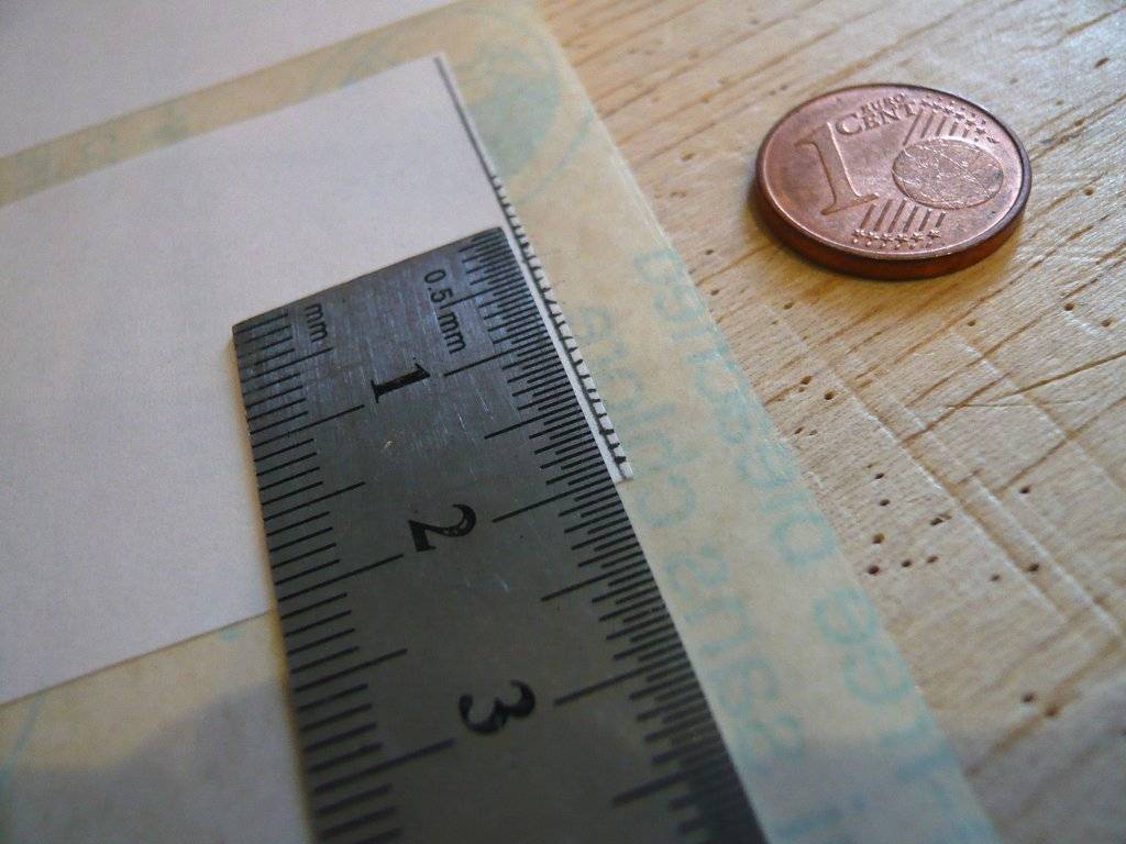 which then were cut off. 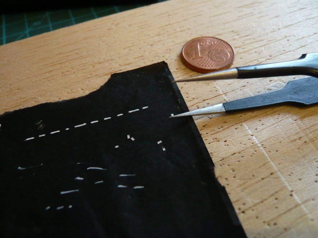 In a crazy action comparable to mouse milking, as it is called in Germany, I’ve then patiently tried to use tweezers and a cutter to form a row that would now be roughly true to scale, while these 'dashed lines' are not so evenly arranged in reality. 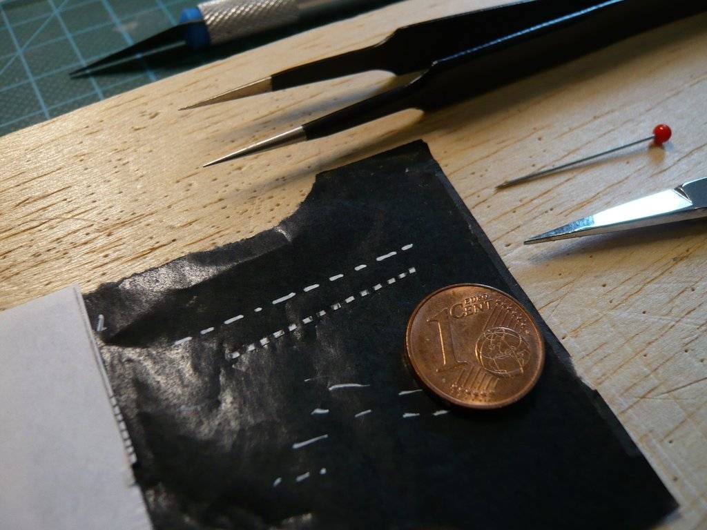 That's why one can see that my lines are too long, but with the permanent marker (Montana Acrylic) you can't draw such tiny dashes, at best you can only hint at them. Then, during my research, I came across some NASA original photos that I had not previously seen. Upon closer inspection, I became aware of further details that plays havoc with my previous view of these rod systems and their foil cladding, which is why I have to rethink and modify my previous solution approach. As one can see in this image (zoom!), the area between the rod systems behind the X-Band High Gain Antenna is not open, but is also covered by dark foil with such strips, which means that the bottom part of the antenna is literally enveloped from behind,  Source: NASA which can also be seen from this image (zoom!).  Source: NASA The bottom part of the antenna is also covered in dark foil all around, which I had already noticed and still needs to be taken into account. That's why there are crossbars on the rear rod system that run diagonally downwards for attaching the film, which one can just about see in this image,  which appear under the cladding in this image too. 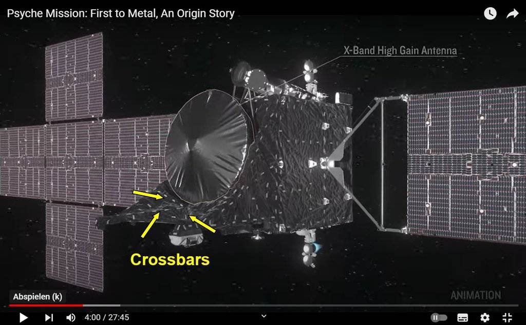 I now have to try to put these new insights into practice. There's nothing like good NASA original photos, you just have to know how and where to find them.
__________________
Greetings from Germany Manfred Under construction: Launch Pad 39A with Challenger STS-6 (1:144) Last edited by spacerunner; Today at 05:15 AM.
|
| Google Adsense |
 |
|
|


 Linear Mode

