


|
|
|
#1
 01-13-2010, 01:53 AM
|
||||
|
||||
|
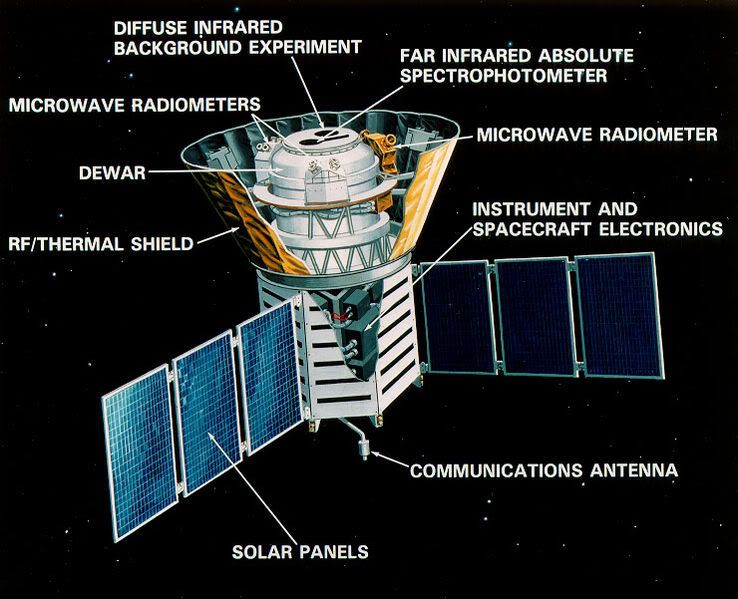
Yogi's Cosmic Background Explorer (COBE) 1/24
I'm getting started on a test build of a new model by Yogi, namely the Cosmic Background Explorer (COBE) spacecraft. This was a request of mine, so I'm pretty happy to be assembling it!
 I'm starting out with the spacecraft bus, which is simply two similar pieces that fold up into a hexagonal box with sealed top and bottom. 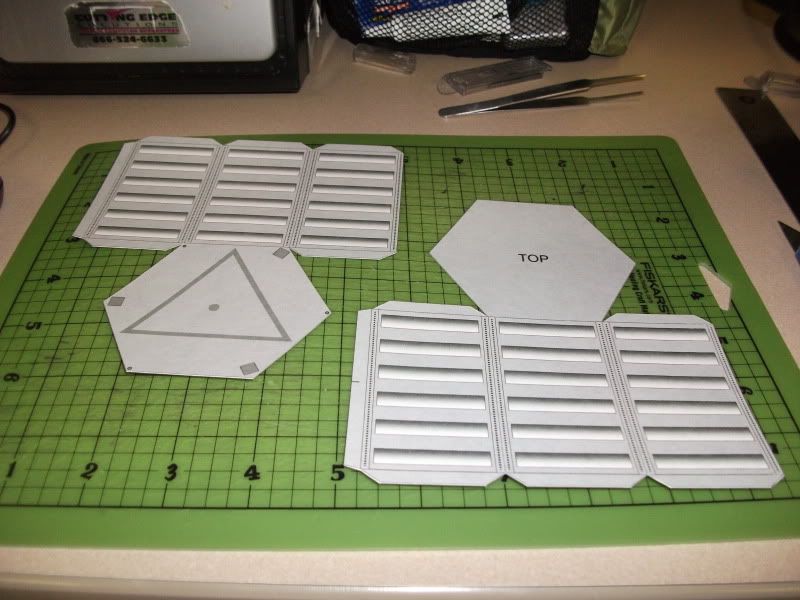 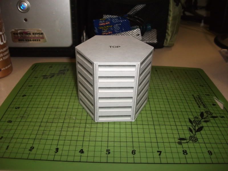

|
| Google Adsense |
|
#2
01-13-2010, 02:56 AM
|
||||
|
||||
|
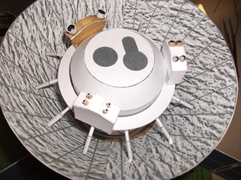
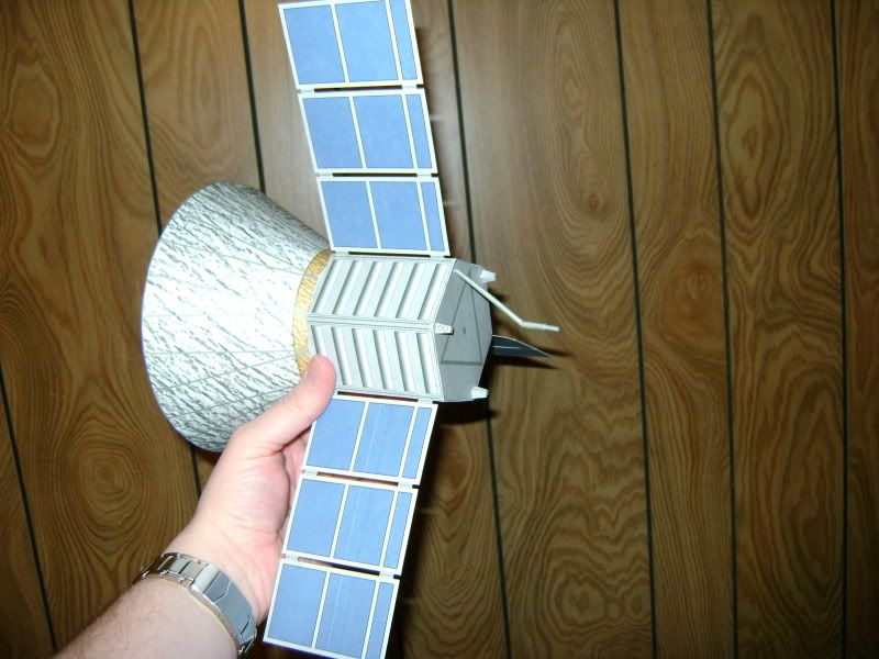
Next is the dewar, which consists of a truncated cone atop a cylinder.
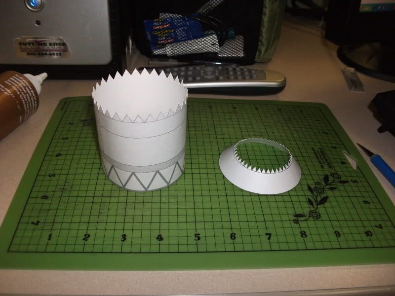 I assume (realize that I may be quite wrong) that the disk at the apex of the cone requires the keyhole shaped slot and the circular hole to be cut out, so that the dark gray disk can be attached to the backside to provide some depth. Yogi will have to confirm that, although I must say that it helps match the part to what the real spacecraft appears to look like. 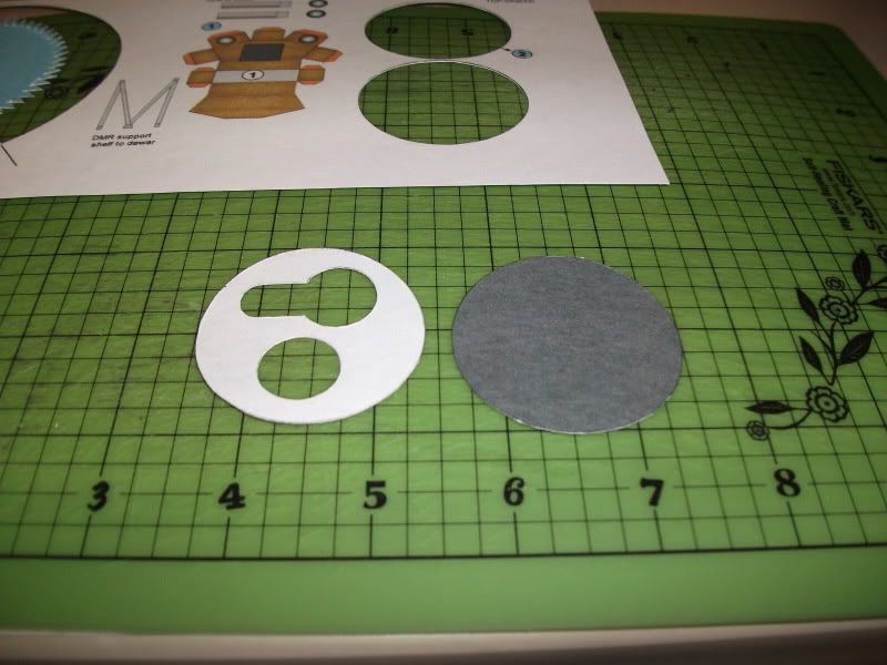 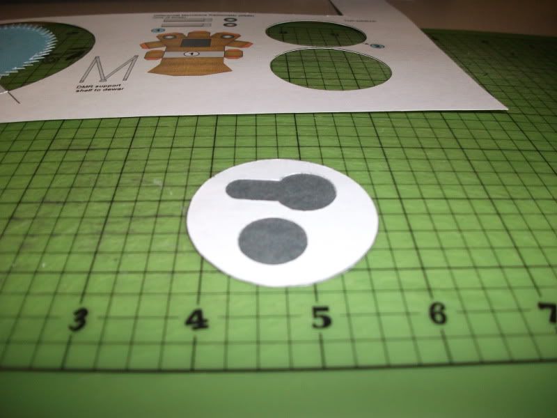 The entire assembly is mounted to the bottom disk, laminated from two parts. 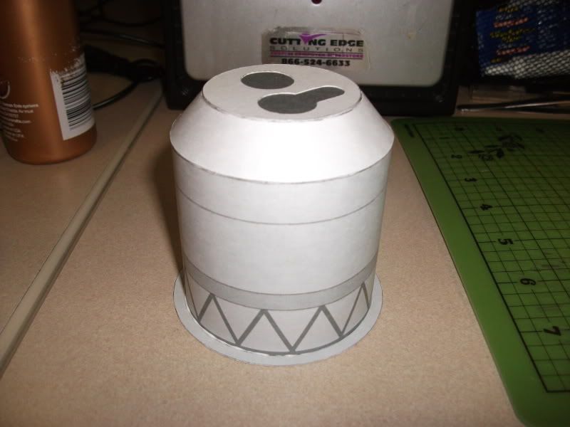 Which is then attached to the bus, being careful to match up the dotted lines on the bottom to the faces of the bus. 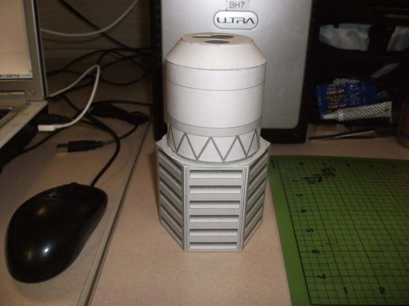
|
|
#3
01-13-2010, 04:18 AM
|
||||
|
||||
|
A question for Yogi: I'm trying to figure out the arrangement of the struts and instrument shelf. It seems like there should be a raised band about 1/4" wide where the stripe printed above the printed struts are. I was going to build it up to attach the struts holding the instrument shelf, but a part for it may be helpful in any revisions. Any thoughts on this? So far everything else is going together smoothly.
|
|
#4
01-13-2010, 05:28 PM
|
||||
|
||||
|
J - looks great so far!
The two top disks are designed as you noted. You can glue the dark one under the conic's tabs and the one with the "keyholes" over the tabs to provide a little more relief. Orientation from the blueprints and pictures. One caution - the instrument shelf is larger than the opening at the bottom of the shade. Probably best to build up the bus and shade, reserving the Dewar/instruments/DMR supports as a separate assembly to set down inside the bus/shade assembly, then attach struts to the shade. The instrument shelf mounts to the Dewar at the line near the top of the Dewar cylinder. The "shelf support band" on the same page as the shelf wraps the Dewar below the mounting line to help locate the shelf (if the shelf is a loose fit you may need to block out the support band). The DMR support struts just spot glue to the edge of the shelf below the instruments, then the bottom is spot glued to the Dewar (probably best to install the shelf, instruments, then the struts). The struts should land on the top edge of the gray band on the Dewar (yes, there should be another conic for the Dewar bottom and a wrap-around set of lower struts holding up a mounting band; decided to punt that for the future since it's a fairly well hidden part of the satellite). Similarly, the sunshade struts go from the center of the rectangular areas on the shade (gray spots might be hard to see, another revision needed?) and up to the lower side of the shelf (you can cut them to exactly reach to the edge or just spot glue to the underside of the shelf; either way the shade ends of the struts should set just about square to the shade surface - helping the gluing). Yogi Last edited by Retired_for_now; 01-13-2010 at 09:07 PM.
|
|
#5
01-14-2010, 02:27 AM
|
||||
|
||||
|
Thanks for the insights. I can see now where everything fits.
I had already blocked off the band directly above the row of printed struts, which will make placing the DMR supports easier if anything, and add a little relief anyway. (I'm testing the theory, anyway -- it really does set off the interior just from the shading it provides.) I know it isn't prototypical, but it's helping me place the supports with more accuracy. (I have large, dumb fingers.)  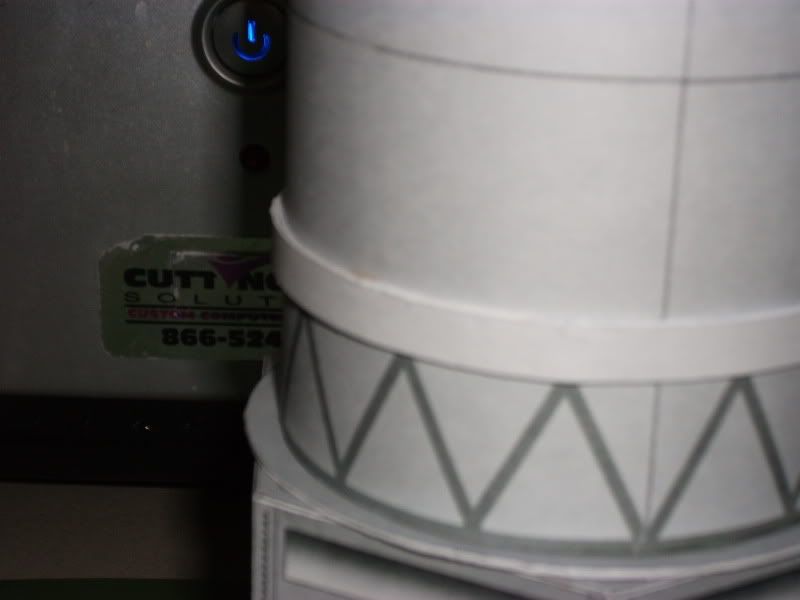 I also blocked off the instrument shelf support, as the hole in the instrument shelf was slightly larger than the dewar diameter, but not enough to really merit a change in design, honestly. If it was me, I'd just add another length of support strip, since that's what I did, and it was fine. Assembling the shade was easy, and I only had to shave about 1.5 mm from the edge of the final section to make the sections line up. Once I dropped it into place, with the correct shaping it came to the edge of the supporting disk easily. I had already glued the bus to the dewar, and attempts to separate it may have damaged it. I left it in place and told myself I'd be able to hammer it together anyway. Live and learn. I'm going to assemble the instrument shelf parts and drop it in place completed at the end, and I seem to have plenty of room to work, even with large fingers. 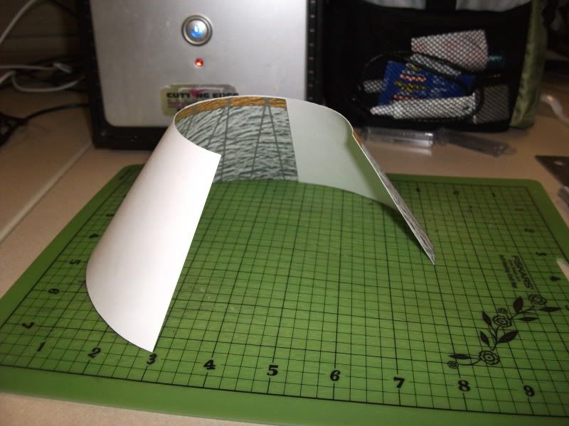 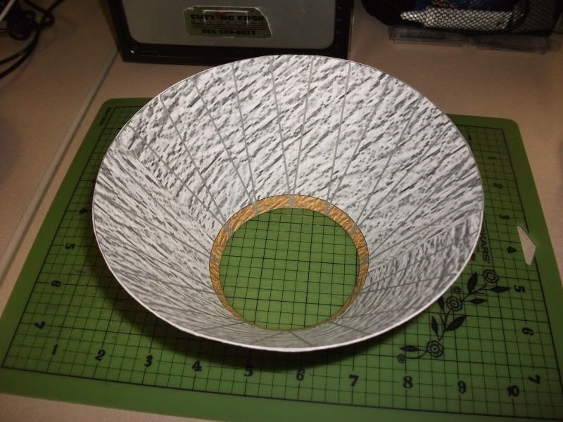 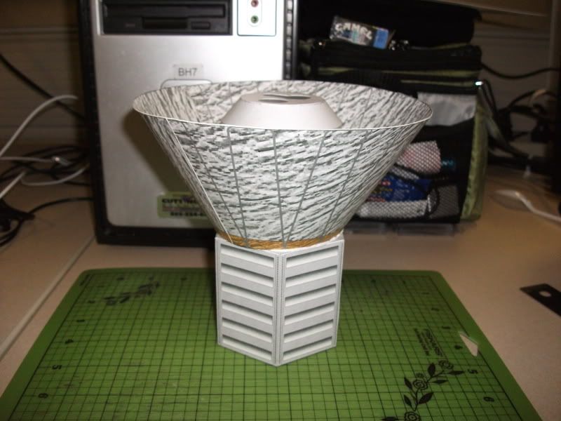 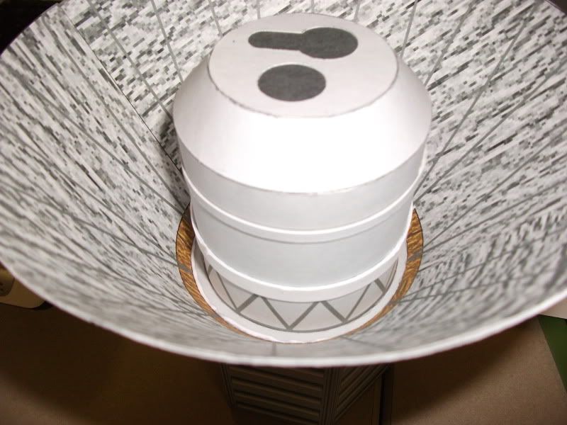 And you weren't kidding -- at 1/24, this is a good sized model! 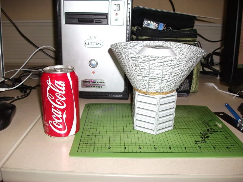
|
| Google Adsense |
|
#6
01-14-2010, 05:02 AM
|
||||
|
||||
|
Next up: three Differential Microwave Radiometers and the instrument shelf, plus the associated supports mounted to the dewar.
Because I had to attach the sunshade to the bus first, attaching the supports was going to be, I assumed, a little harder. It was not, actually. I mounted the supports to the dewar using the raised bands as a guide and as support. 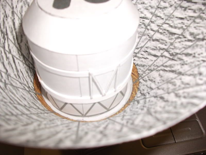 The instruments go next. Each one is a multifaceted box, which is actually quite easy to assemble (just the right amount of tabs on DMR-1 Yogi -- I wouldn't add any more, as the assembly folds right up to the right shape. 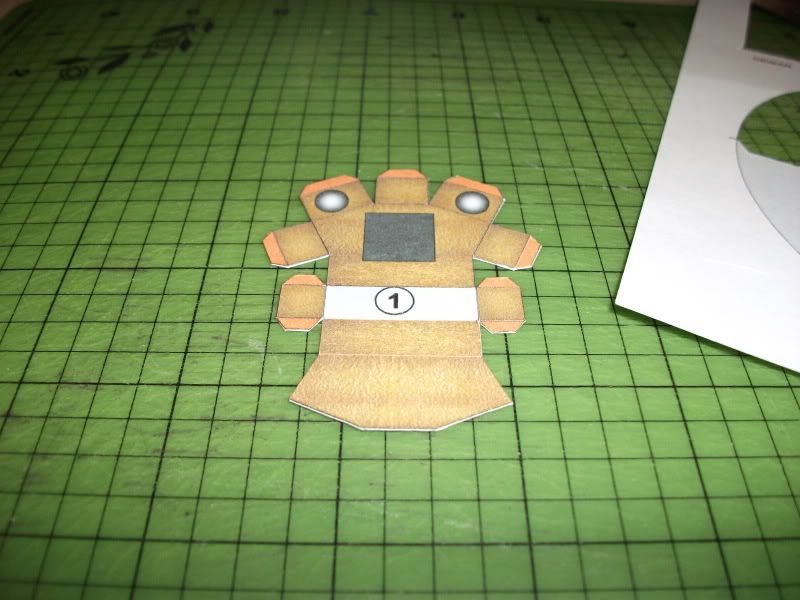 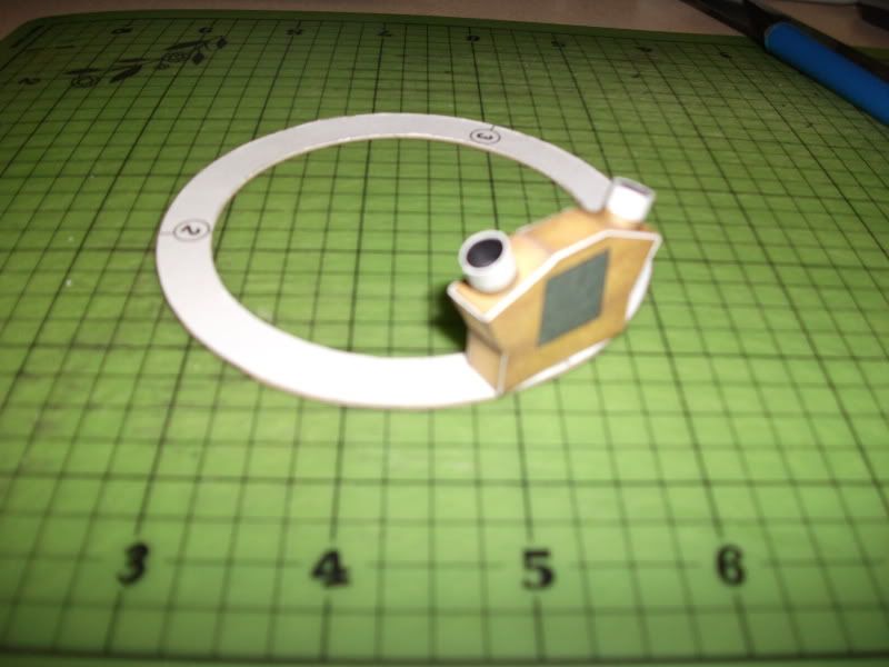 All of the instruments mounted: 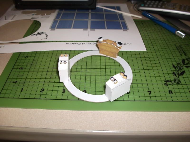 And a dry fit-check (you can still see wet glue inside the DMR barrels): 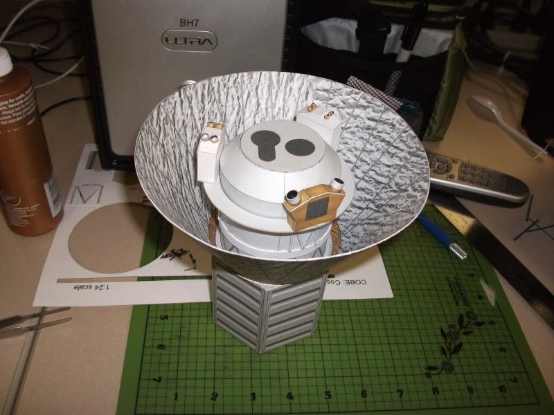 While cutting out the solar arrays, I decided to cut the gray sections out from between the individual panels for some realism. I checked to make sure they lined up correctly first (they do). 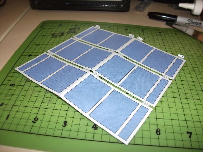 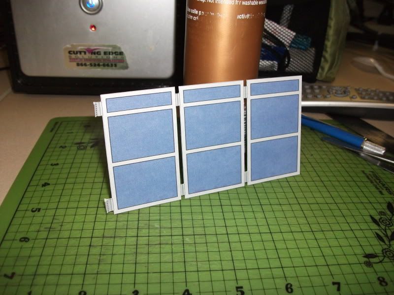 Panel isn't mounted yet. I'm going to do all three and attach them after the instrument shelf and struts are attached. I was waiting for glue to dry so I figured I'd go ahead and assemble them. Next, I am going to attach the sunshade to instrument shelf struts to the instrument shelf with flexible PVA glue, attach the shelf to the dewar, and then move the struts into place and glue them to the shade. There are twelve struts in all, so I figure that will be the most accurate way to make sure they are even. The sensors and antenna on the bottom of the spacecraft will be last, as they are easily the most fragile parts. So far, so good (I hope)! Last edited by jparenti; 01-14-2010 at 05:23 AM. Reason: Added more information
|
|
#7
01-15-2010, 04:45 AM
|
||||
|
||||
|
All dewar-to-sunshade struts built. I attached each one to the edge of the instrument shelf with PVA glue and then placed the instrument shelf in place when dry. I then spot glued each strut to the sunshade with CA glue. (Unfortunately, I misread your instructions on this one Yogi -- I accidentally attached the struts to the TRIANGULAR sections instead of the rectangular ones. I will chalk that up to my sleep deprivation today. I imagine I'll be the only one who will notice, and I will probably have to redo it later just to satisfy my OCD.) :D
 I will admit that it looks good to me, one way or another. I was able to space the twelve struts correctly (as far as I can see), but if you think it would work, you may try adding a part to the kit that laminates to the bottom of the instrument shelf that simply has twelve dots for alignment. I then attached all three solar arrays, according to the blueprints and the various artist's renderings in my collection. I recommend CA glue for that, as it stiffens the attachment points enough to hold them in place at the correct angles, even when tilted. 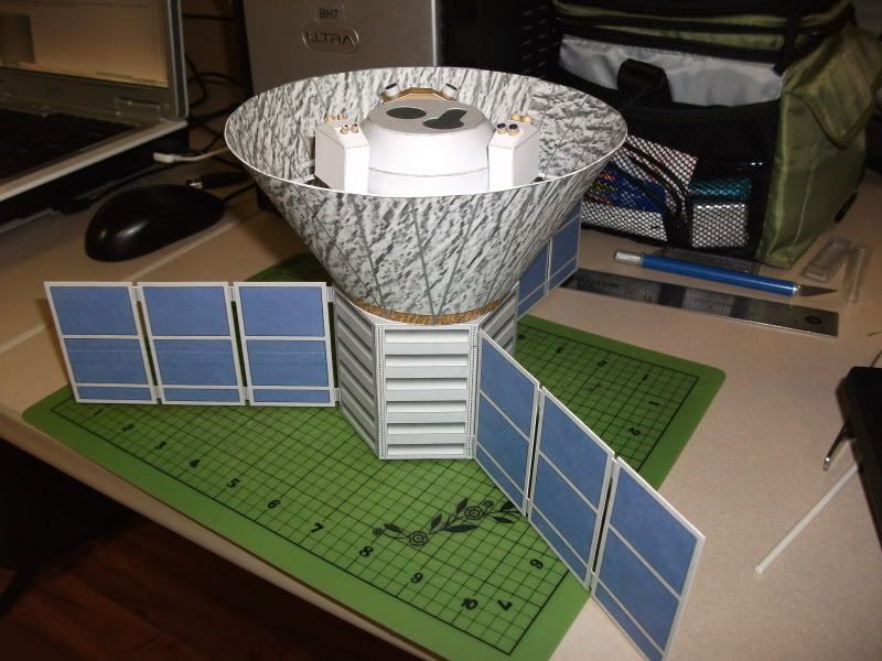 The sensors and antenna mast are next, and then I'll be done. I'm working on a stand as well. This is a good kit, and it goes together very smoothly.
|
|
#8
01-15-2010, 04:05 PM
|
||||
|
||||
|
Looking great - why do your builds look so much cleaner than mine?
BTW - The WMAP team has that model for evaluation, also asked for COBE since they are obviously related (and the COBE dataset is integral to their work with WMAP). Guess I do need to make the fixes noted and write some clear directions. I'll give the WMAP team first opportunity to post the models; else they'll be here or at Lower Hudson Valley. Yogi
|
|
#9
01-19-2010, 05:48 PM
|
||||
|
||||
|
My build is finished!
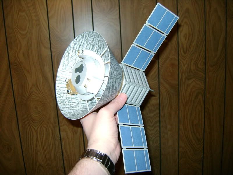  Hoping the antenna mast went on correctly. I used the blueprints and some of the illustrations I had to place it. I used thin wire glued inside the mast to plug it into a hole on the underside of the bus, making it removable for transport. (I always forget to make my various antennas removable, and I always pay for it later when carting the models around. This time I remembered.) I certainly hope it looks cleaner than most of my builds usually do -- a high megapixel digital camera seems to draw out my mistakes and put them to the forefront. :D I hope to see both COBE and WMAP up on the WMAP project website soon. These were detailed builds, but very smooth to build, and I'm sure others will enjoy them. I had never seen a spacecraft team put up photos and diagrams for model builders, and I was happy to see they did. It's something that would help us immensely -- just one three-view would be a lifesaver sometimes! I may do another COBE at 1/48 to match my WMAP soon. I'm also working on enlarging WMAP...a little. I gained access to a larger printer than I usually use, so I'm doing a little experimenting. We'll see how that works out later.
|
|
#10
08-13-2010, 05:34 PM
|
||||
|
||||
|
COBE Posted - COsmic microwave Background Explorer
The COBE model is posted at the Lower Hudson Valley Challenger Center (jleslie48.com). If you can drop by the site's home page and make a donation.
Yogi
|
| Google Adsense |
 |
|
|


 Linear Mode

