


|
|
|
#1
 10-03-2010, 02:48 PM
|
|||
|
|||
|
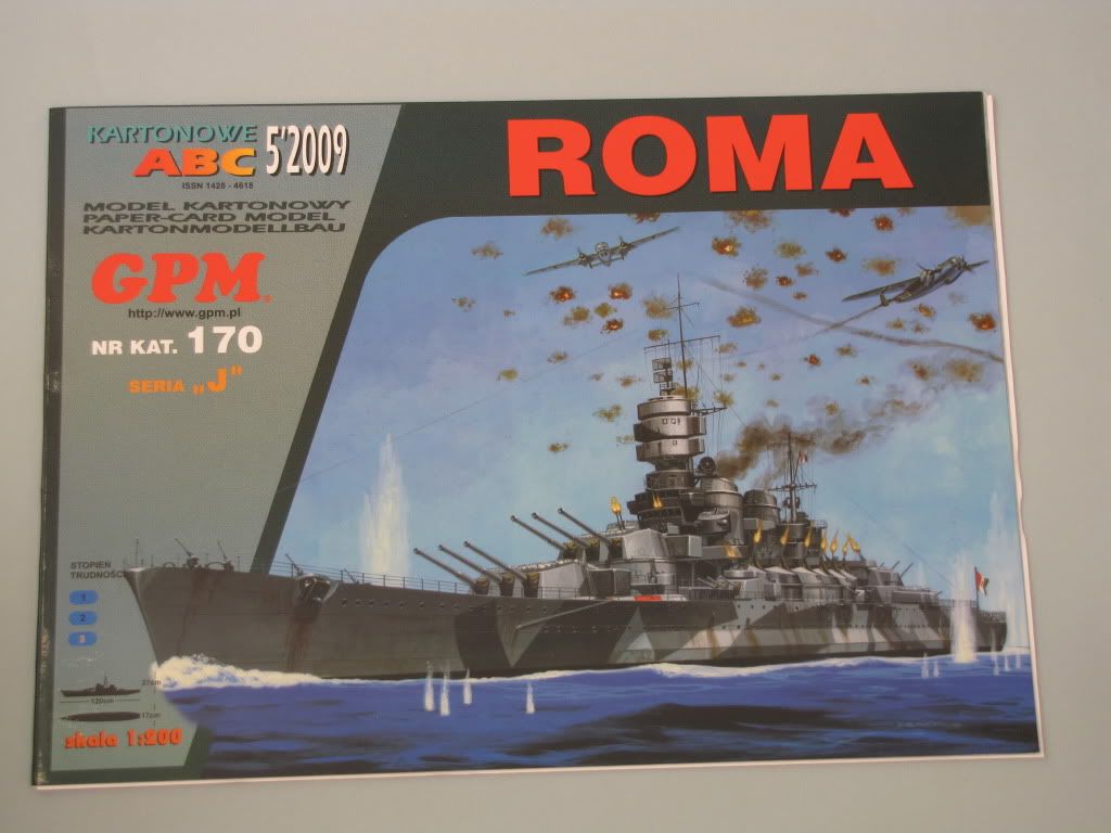
GPM Roma 1/200
The GPM model of the Italian battleship Roma was ordered directly from GPM - modele kartonowe along with the laser cut formers (or frames), a photoetch set, and a set of metal barrels. I ordered two copies of the card model which would allow me some wiggle room in case of mistakes and also allow for experimentation. Ordering from GPM in Poland was easy as the website let me choose a display in English. The order was quickly shipped and well packaged. I ordered this model about 6 months ago and I cant remember the cost of individual components but the card model alone was about $30 dollars. I think the painting on the cover is great but I understand it may not be to everyone's taste.
 The card model has instructions only in Polish and diagrams which appear somewhat cryptic. The exploded parts diagram on the bottom right of the page below may be typical of GPM models but I find it a bit intimidating. 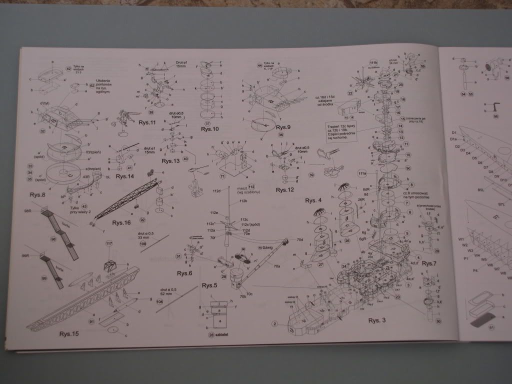 My soon to be son-in-law is a Polish citizen and was kind enough to translate the instructions into English. The sides of the hull and the decking with the red and white identification stripes as printed show nice weathering. As I have read elsewhere, the bottom of the hull should not be red but green and the identification stripes should not extend past the forward most turret. I will definitely be painting the hull green but I am undecided if I want to get into modifying the red and white identification stripes. 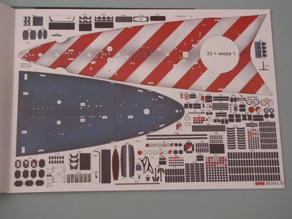 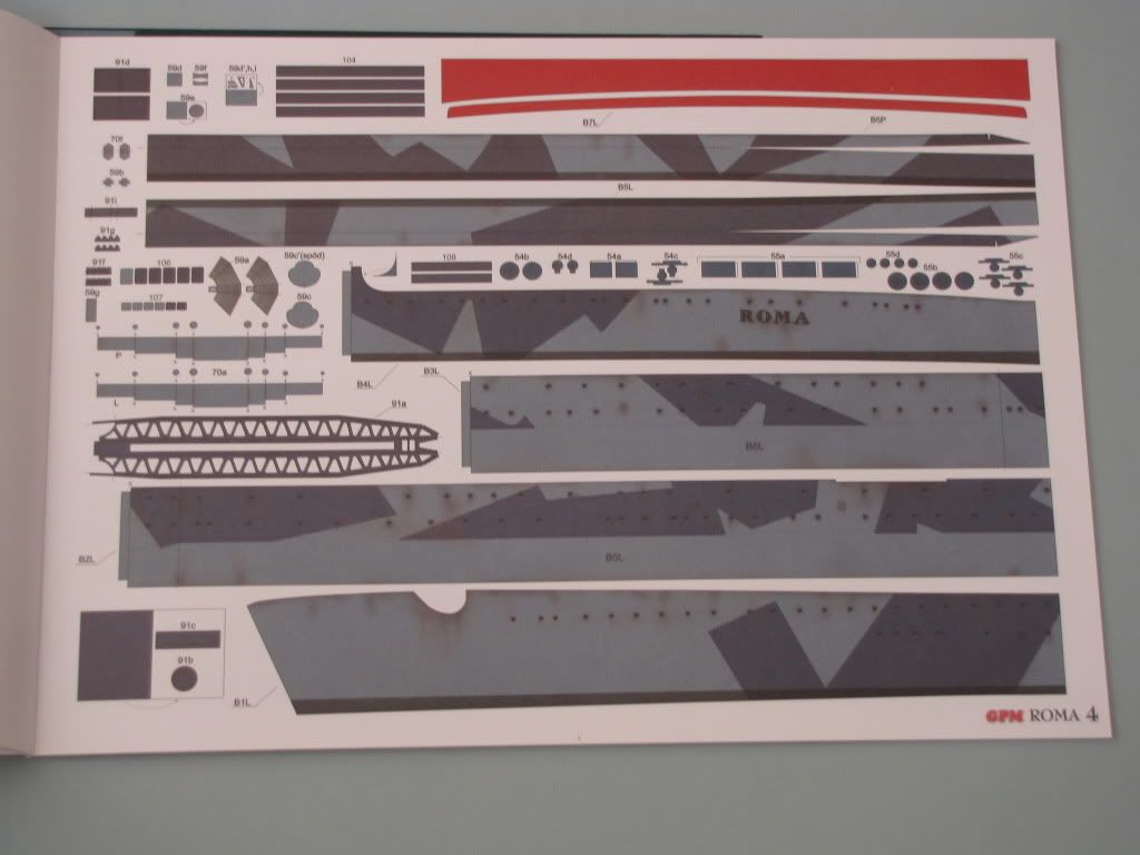 The instructions include multiple photos of a built model. I know that some might criticize this build as the hull is red and the identification stripes extend too far but I think it is a beautiful ship! My current plan is to paint the hull green (I like the green hulls on Italian ships) and weather the green to blend with the printed weathering. I am hoping that Promodeller weathering washes will work on the acrylic painted paper surface. (Promodeller Home) 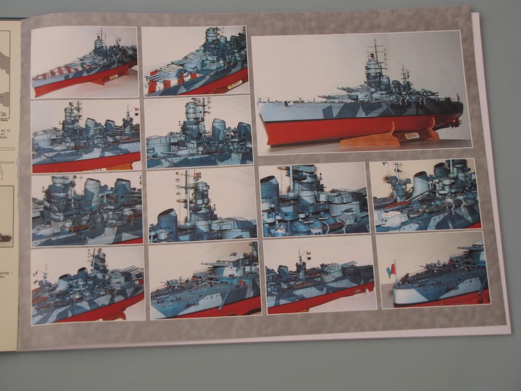 I will include photos of the photoetch set on the next post. Greg 
|
| Google Adsense |
|
#2
10-03-2010, 03:02 PM
|
||||
|
||||
|
Go Greg Go!
I have that one in the stash so I will be watching your build with interest. I agree on the green hull bottom, but I do like the weathering applied to the printing on the pages so I won't be tinkering with that bit of paintwork. Since I have a rather nifty Epson Printer/Scanner, I can forgo the second copy purchase, I am planning on just scanning and printing the whole thing out that way I can save the original for future reference. 
__________________
Jay Massey treadhead1952 Las Vegas, NV
|
|
#3
10-03-2010, 05:52 PM
|
|||
|
|||
|
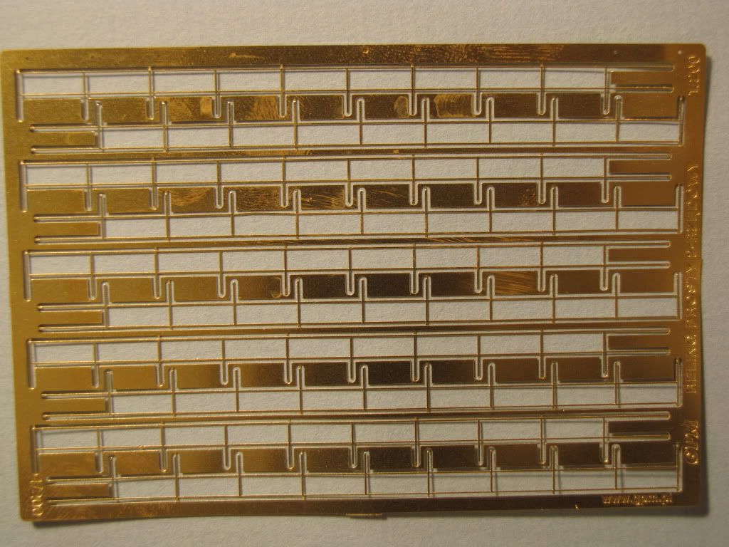
Accessories for the GPM Roma
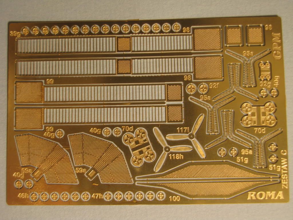
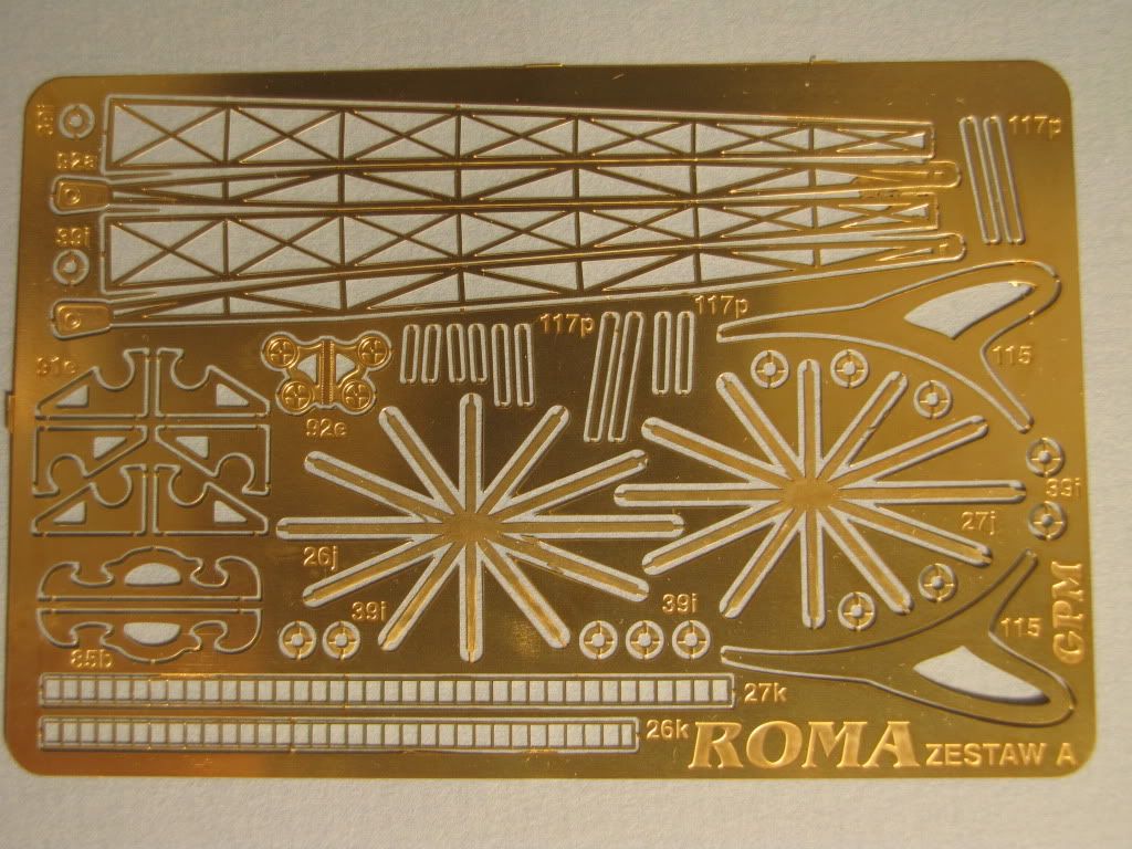
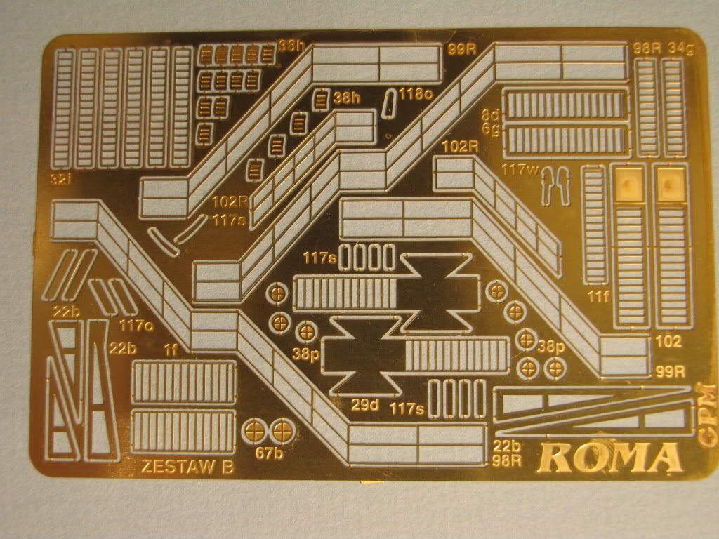
The photoetch set for the Roma is shown below. The parts are numbered the same as the kit parts but otherwise there are no instructions. My experience with photoetch is limited to cockpit parts for one Hasegawa P40 and my first impression is that these parts may be complicated to fold, etc. The one sheet of railings is very small and does not indicate where they go. GPM may sell a complete set of 1/200 railings but I am undecided about whether to go that route or thread coated with superglue.
    The set of cannons is shown below. I will follow up with pictures of the individual components at a later time in the build. 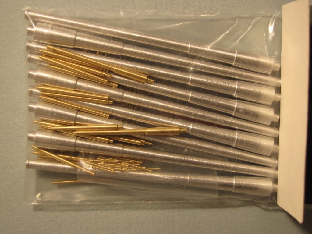 The laser cut formers are not acid free (as I noted in a separate post). I was considering not using them but a member of this forum pointed out that Krylon makes a product called Make It Acid Free which is, I believe, calcium carbonate. I sprayed both sides of the formers and will make sure there is a thin coating of Aileens Tacky Glue where the formers attach to the overlying printed parts. I needed a full can of the Krylon product to treat both sides of the formers and the product is not cheap at $12 for a large spray can. (Sorry, I did not take pictures of the formers before I separated them.) It seems a better use of the $12 would be towards acid free cardboard for the laser cut formers. Next - assembly of the skeleton. Greg
|
|
#4
10-03-2010, 09:02 PM
|
||||
|
||||
|
Hi Greg,
That looks like a pretty nice set of Photo Etch parts, the only difficult to fold item looks to be the aircraft crane and with a couple of straight edged razor blades, one to hold a section down and the other to act as a folding tool, it shouldn't be too difficult. The rest of the platforms and stair sets are easy enough and they have included some nice railings to use for forms to guide you in bending them up. It should save you a lot of time trying to come up with ladder ways and such on the bridge and deck houses. I would try and come up with some more railings from GPM to outfit the rest of the deck space since you have some to work on the structures, it will aid in giving a uniform appearance. Those are some nice barrels as well, I have a few sets of those and if you can get a nice tightly rolled axle to drill a hole into to seat them adding them to turrets is a snap. With the larger caliber guns being made in aluminum to save some weight over brass, making up the main turrets becomes far easier. The smaller brass barrels should look rather nice using the kits gun mounts, the paint choice being the biggest thing to overcome there. I look forward to seeing how you come along with this one. Take your time and watch those #11 blades, I take a blood thinner too so I know where you are coming from there.
__________________
Jay Massey treadhead1952 Las Vegas, NV
|
|
#5
10-04-2010, 05:38 AM
|
|||
|
|||
|
thank you very much
|
| Google Adsense |
|
#6
10-04-2010, 12:16 PM
|
|||
|
|||
|
Assembling the skeleton
The bottom half of the hull went together easily with the laser cut formers. With the ship measuring about 57 inches you will need a long ruler to make sure the false keel and "deck" for the lower half are straight.
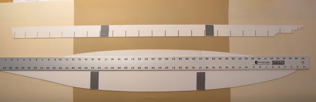 I also checked that the length of the false keel and the "deck" were the same. I lined up the stern 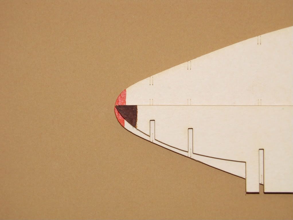 and then checked the bow. The discrepancy was small (For reference the slot in the photo is 1mm wide) and I considered it ok for my purposes. 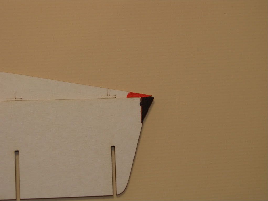 I don't like to work fast if I can avoid it so I did not try to assemble the lower hull half by gluing it up at one sitting and then piling books on top to keep the assembly flat to the building board (as the instructions indicate). Instead, I held up the false keel perpendicular to the "deck" with a metal square and a plastic clamp. I put a little duco cement along the flat surface of one frame and inserted it into the appropriate slot making sure the false keel was centered on the "deck" and using another square made sure the frame was square to the false keel and perpendicular to the "deck". 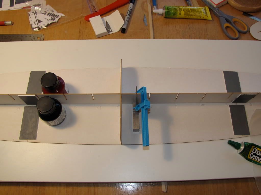 Holding the components in place for about a minute lets the duco cement set up enough to stabilize the components in the right position. Now the hard part - go do something else for 15 minutes. With duco cement (and probably other solvent based cements) you do not get warping of the cardboard like with water based glues like Aileene's tacky glue or elmers glue. When you come back after the 15 minutes, everthing will still be sitting flat on the building board and the glue has set enough to continue. Now I run a bead of duco cement along a short segment of the false keel where it meets the "deck" (just from the cemented frame to the next frame slot) and place the square and plastic clamp on the false keel ahead of the glue and frame slot (so the square doesn't get glued up). The next frame gets a bead of glue and into its slot. Hold for a minute and then leave it alone for 10 minutes. The onto the next segment of keel and frame. It has taken me longer to write about it than to cement each frame. Except for the waiting period between frames, the whole process takes little actual modeling time. And, with the duco cement when you come back to the finished lower skeleton it will by perfectly flat with no warpage. 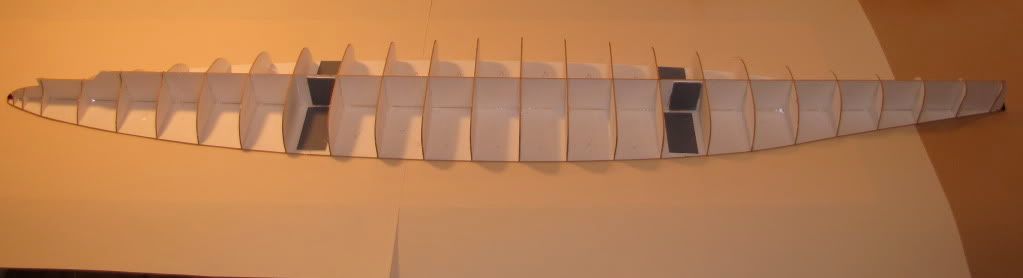 Next: The upper half of the skeleton. Greg
|
|
#7
10-06-2010, 08:54 AM
|
|||
|
|||
|
The upper skeleton and main deck
Hello again,
Reading my last post, I noticed it sounded like I know what I am doing. I need to put in a disclaimer that I don't know enough (about anything) to give advice (about anything). Probably best to consider these posts for entertainment only. The upper half of the skeleton was put together just like the lower half. 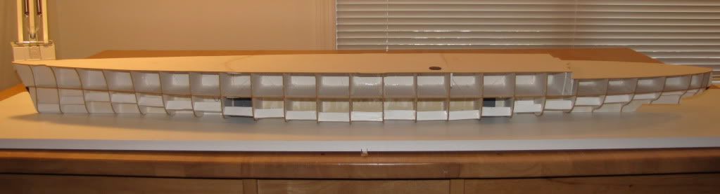 Several closeups also show the "stiffeners" I placed between frames on the lower half of the skeleton. 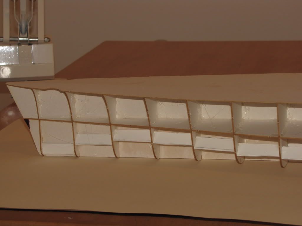 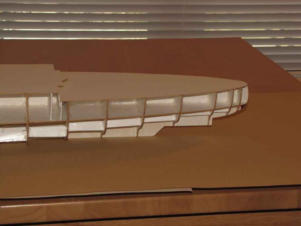 I don't know if the "stiffeners" really accomplish much. I also glued down the laser cut components that make up the deck using duco cement. At this point the hull was still sitting perfectly flat on the building board. The next task was to glue the printed deck pieces onto the cardboard deck. There are 4 pieces that make up the printed deck. I used Aleene's regular tacky glue to attach the forward most piece with the identification stripes. I put some beads of glue onto the cardboard and smoothed it with an old credit card (A technique I read somewhere on this forum) and made sure there was the thinnest, even layer of glue. I laid the printed piece down very carefully and smoothed it with my hand. I let it dry overnight and was very satisfied with the result. I wish I could say everything went smoothly on the next printed piece of the deck. I was out of regular Aleene's tacky glue but had a bottle of Clear Aleene's tacky glue that I had been meaning to try. What could go wrong? I put down the bead of clear Aleene's but when I started to spread it with the credit card, I couldn't tell how thick the glue was. A wise move might have been to scrap it all off, let it dry and start over. I elected to put down the segment of printed decking. It seemed to go down ok. Maybe 20 to 30 minutes later I walked back to take another look at the model and the printed decking has buckled up into bubbles and folds. Even worse, the bow and stern had each lifted up about a centimeter off the building board. I should have taken pictures but I was a bit too worried. I put a sheet of wax paper over the deck and piled on a bunch of books until the skeleton settled back on the building board. I let it sit for 48 hours to be sure the glue was dry. When I removed the books the printed deck was nice and flat except for a few ripples in a white area that will fortunately be hidden later in the build. The skeleton settled back into its prior shape except for the bow being just two millimeters off the building board. The rest of printed deck went down fine using Aleene's regular tacky glue. (The printing on the GPM sheets is surprisingly resistant to waterbased glues. If I had been using ink jet printed deck pieces, I am sure I would have seen the ink run and the pieces be ruined.) 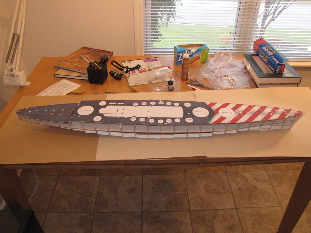 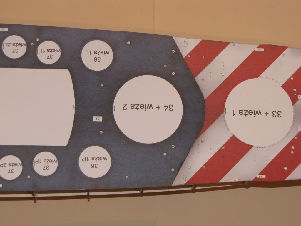 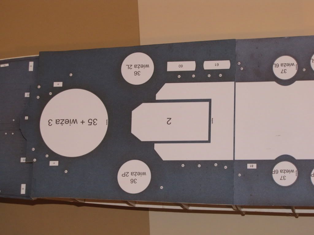 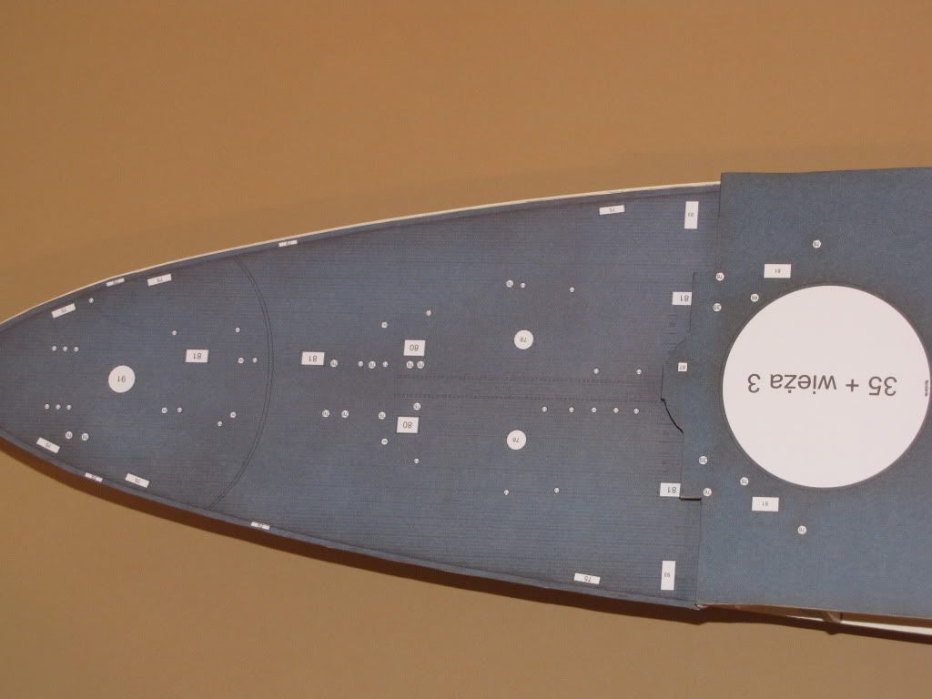 I also inserted into the bottom of the framework two boxes that will serve for the attachment of the spindles on a display board. 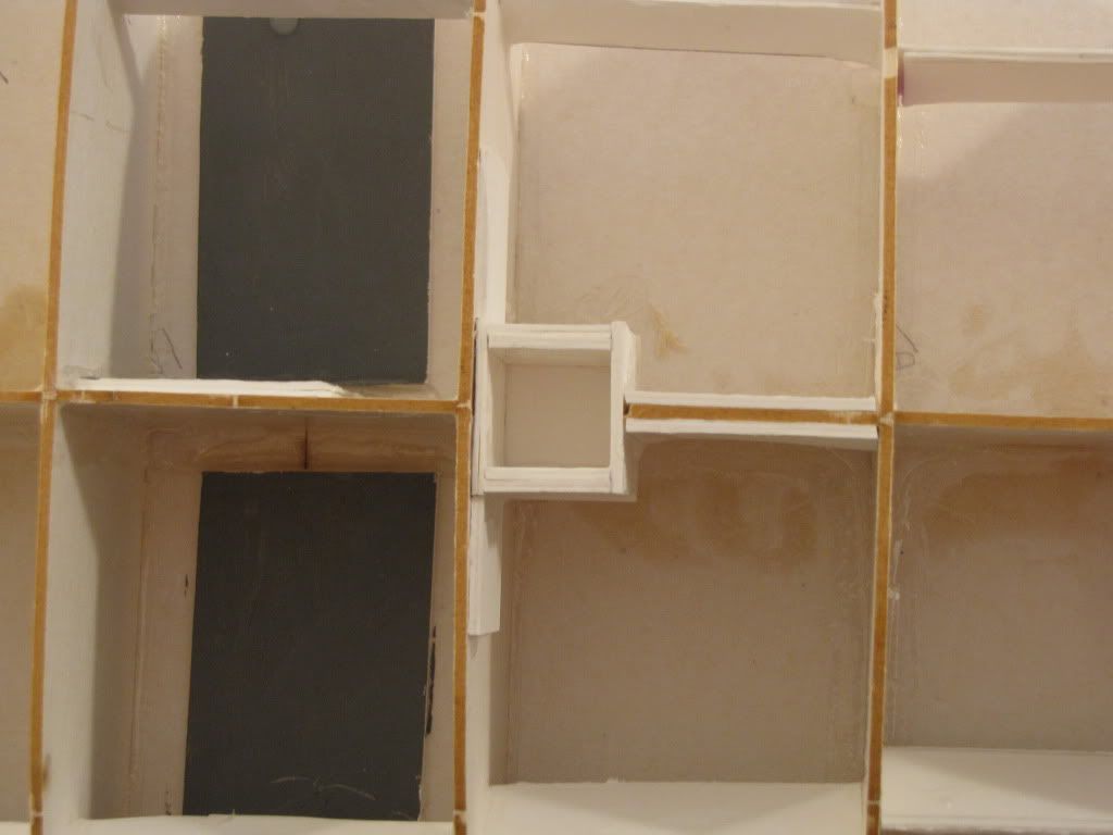 Below is the display board (mahogany) with the spindles (walnut). Everything was stained with walnut stain and a couple of coats of semigloss polyurethane. 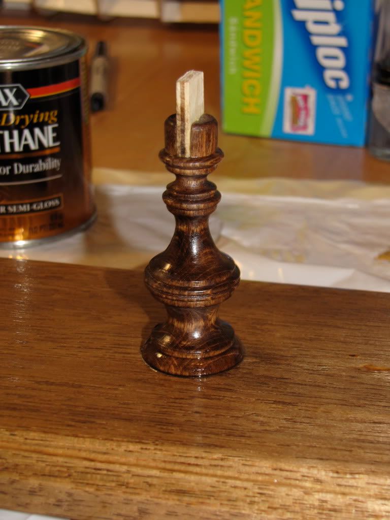 Here I have placed the skeleton onto the display board just to test the fit. 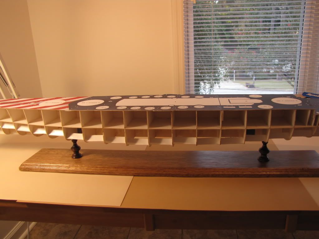 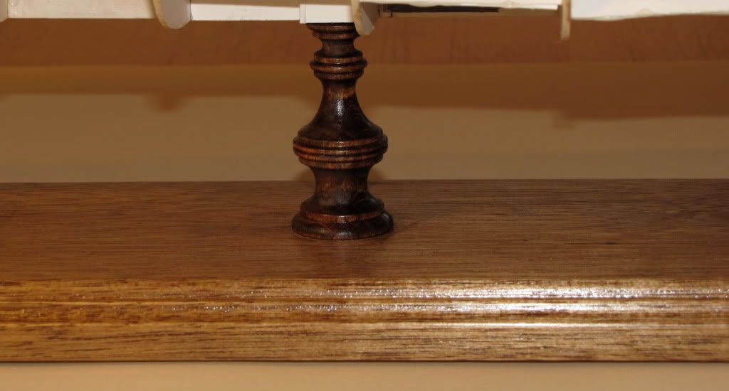 After the hull plating is put on, I will glue the board to the model with five minute epoxy. Next - Hull plating Greg
|
|
#8
10-06-2010, 09:29 AM
|
||||
|
||||
|
Great project. Good luck!
__________________
completed: MH-53 WIP: USS Saratoga (CV3) GPM http://iligan3dpapermodeler.blogspot.com/
|
|
#9
10-06-2010, 09:52 AM
|
||||
|
||||
|
Good work, I like your base and the way you came up with the attachment points.
__________________
Jay Massey treadhead1952 Las Vegas, NV
|
|
#10
10-06-2010, 01:48 PM
|
||||
|
||||
|
On a model that size, I don't think you can ever 'over-stiffen'...
__________________
Please critique my posts honestly i.e. say what you think so I can learn and improve... The World According to Me
|
| Google Adsense |
 |
|
|


 Linear Mode

